4. Electronics production
The route I will learn to make my own electronics production is …
To make it (w4), to design it (w6), to program it (w8).
And what is output (w10) and input (w12), and how do boards communicate (w14).
And finally, make an interface (w16) for it and use (w18) it
So in this week, I did..
CNC cutting PCB board.. and solder it..
Links & Files
- Tobin's w4: Our groupwork this week is on Tobin's site, Thanks for documenting!
- Fab Mods: A powerful tool made by Neil. We use it to make .rml file for milling this week.
- How to solder: A nice guide to learn soldering.
- SMD Soldering Tutorial: A good guide to learn soldering SMD. Files this week
- linetest2022 (Saverio modified): traces, cut
- SERIAL-UPDI (Saverio modified): traces, hole, interior, Thank you Saverio!
PCB fabrication
To make a PCB With CNC machine is more convenient and safter than acid etching.
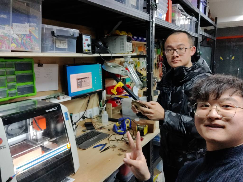
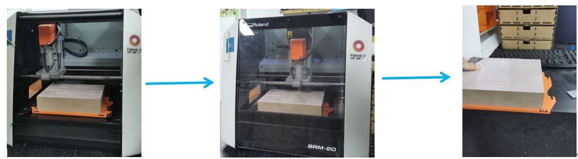
So in Fablab O shanghai, we use Roland SRM-20 to fabricate our own PCB board.
Remember!
-
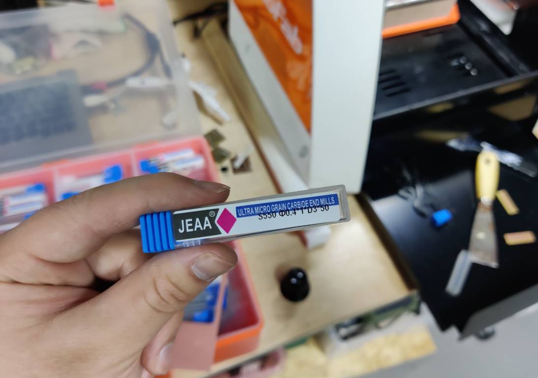
We use 1/64inch (0.4mm) endmill to do tracing. So please make sure no gap is less than 0.4mm before milling.
-
Use 1/32inch (0.8mm) endmill to do cutting and drilling holes. So the hole which is less 0.8mm will no be drilled.
-
And we use FR1 board to fabricate. Other materials like FR4 will damage the endmill.
Characterize our CNC machine (G.A.)
(Group Assignment with @Tobin)
The most inportant rules are post in the previous part, here are some brief review.
Learn more about what we did? The detailed content is documented by @Tobin this week, so pleace go to his page
-
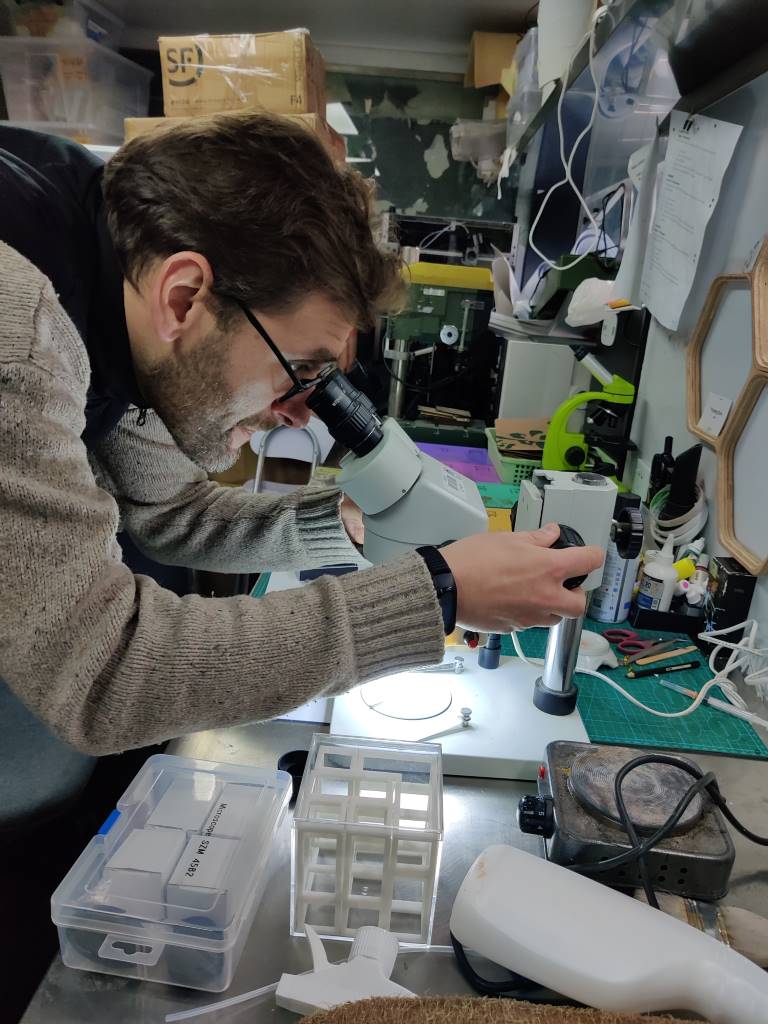
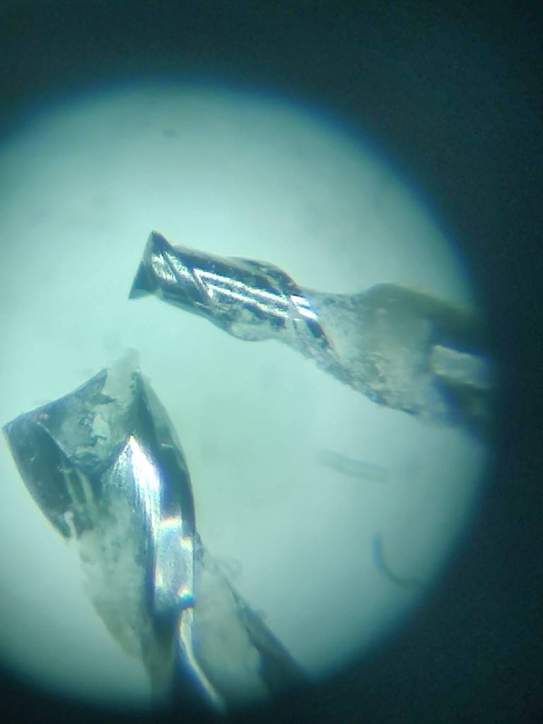
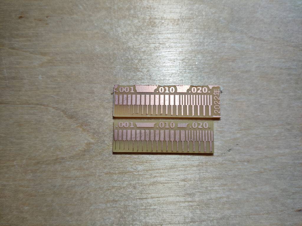
Before start, we observed this 2 different endmill with microscope.
-
We download the Linetest file (modified to include the year) from Saverio.
-
We use Fab Mods site to transfer PNG files to RML files.
-
Operate the Roland SRM-20 carefully, to avoid breaking endmill
and instructor’s temper (A Neil’s joke hahahah)
Pick a programmer
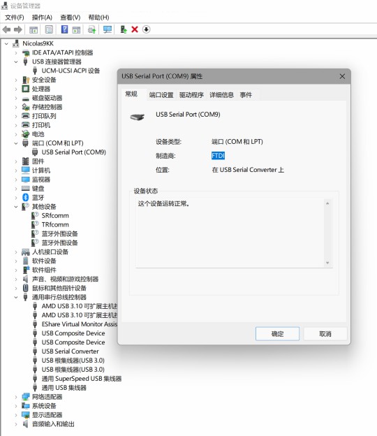
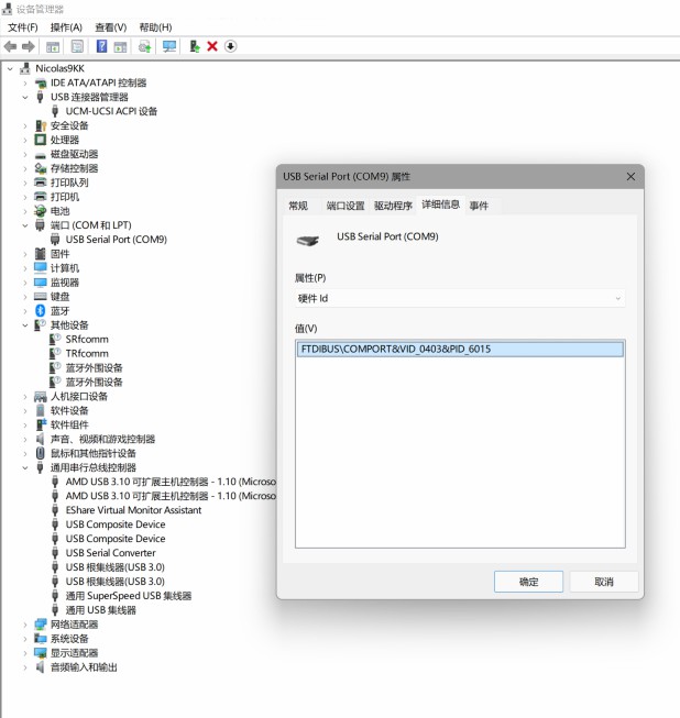
USB-serial.FT230X
Saverio told us that we used to use Fab TinyISP, but it’s too old, and always meets tons of problems.
So this year, we start to use something new…USB-serial.FT230X.
And the MCU(micro controller unit) will be Attiny412, AVR-1
USB-serial.FT230X use UART and USB Type-A to communicate.
UART (Universal Asynchronous Receiver/Transmitter), a kind of serial interface, is similar but different from any other SSI (Synchronous Serial Interface). It features parallel input and serial output.
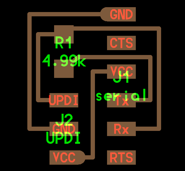
Serial-UPDI
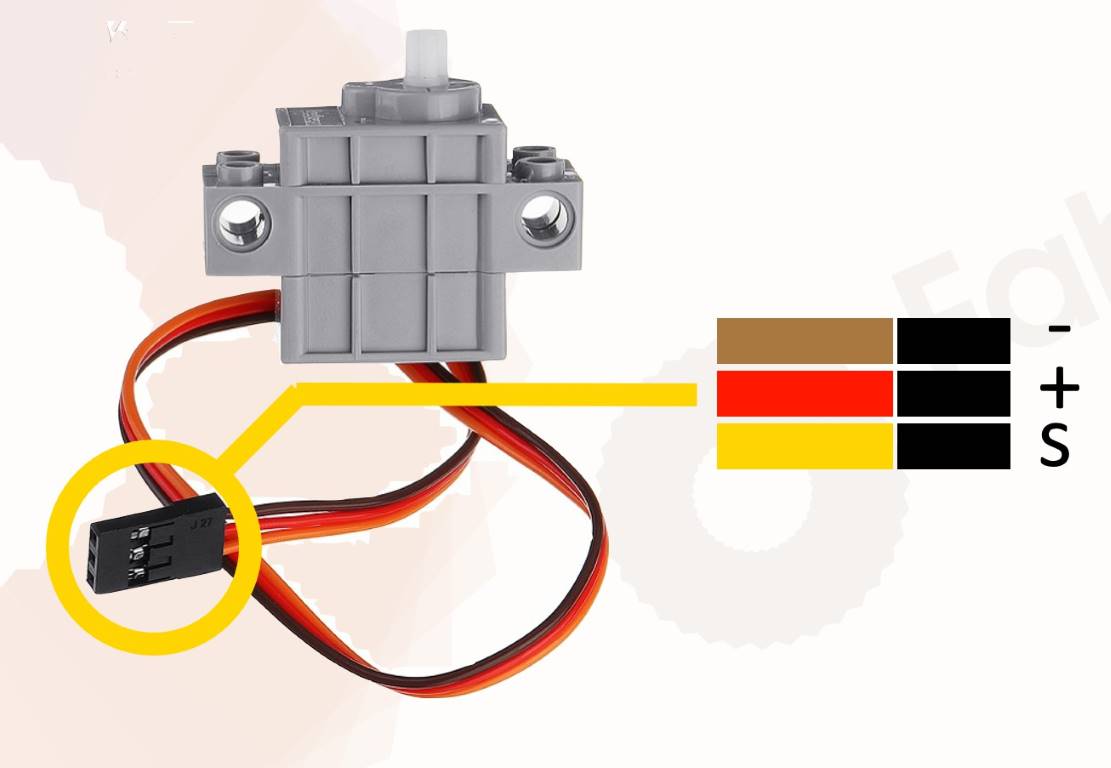
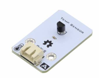
In order to communicate with other input/output device, we need a UPDI interface.
Saverio modified the Serial-UPDI that Neiled designed. He put the VCC pin between the UPDI pin and GND to adapt the I/O device we will use. Thanks!
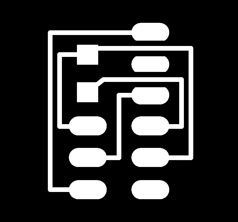
Process png
- Search and download it from here, both of traces.png and interior.png.
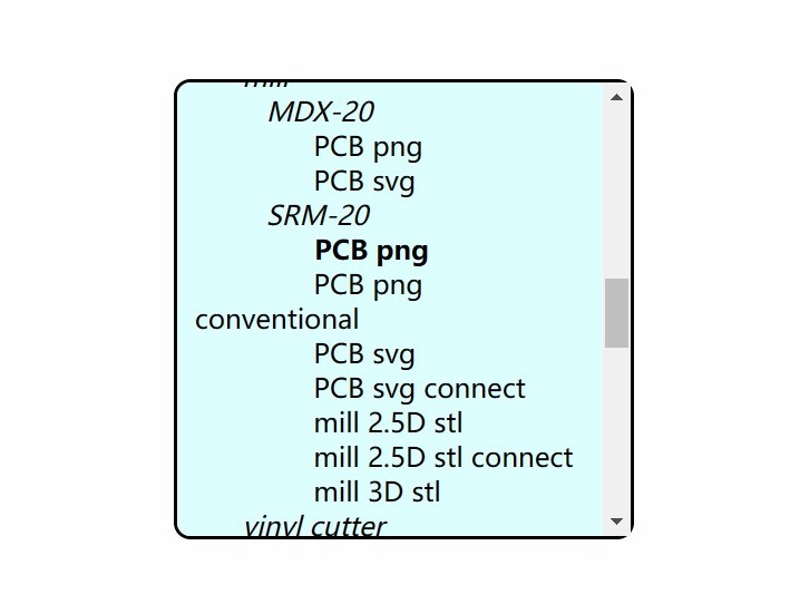
- Open Fab Mods, right click -> programs -> open serve program -> machines -> Roland -> mill -> SRM-20 -> PCB png
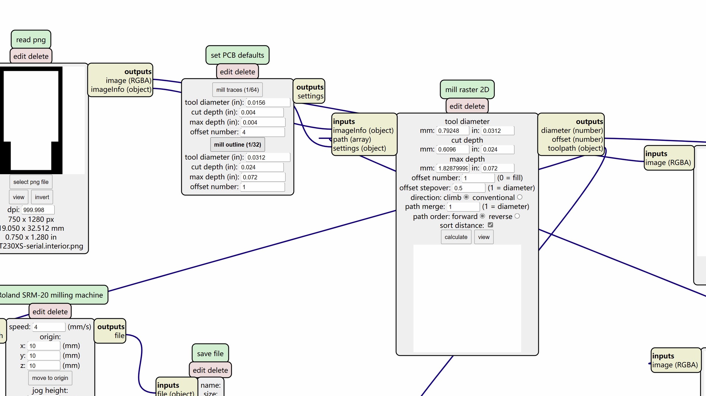
- And you can get the whole convert program like this,
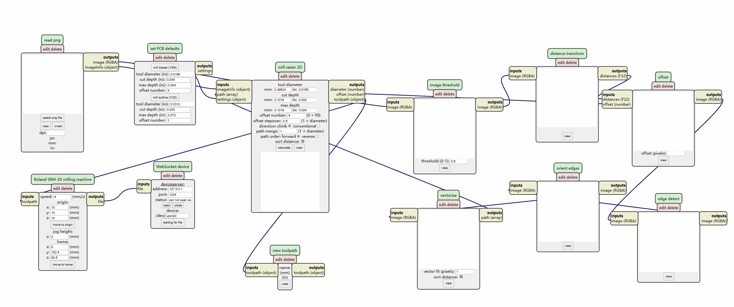
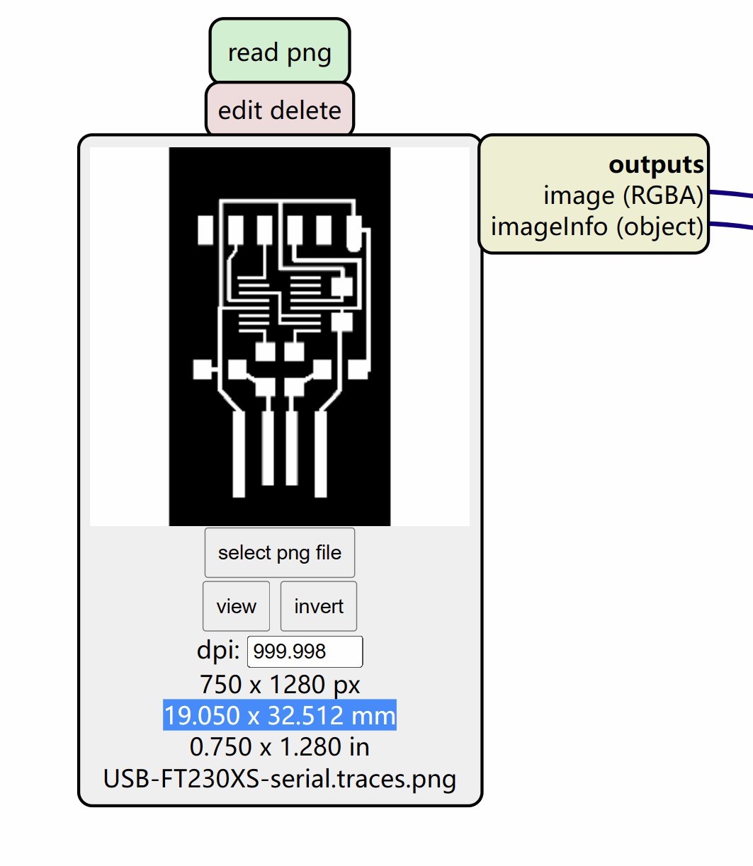
- On the left side, the read png module, select the trace file or hole/interior file of the board. PLZ check if it is 1000dpi, and double check the size.
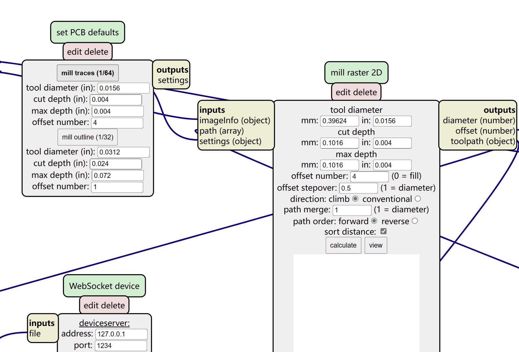
- Choose and click mill traces (1/64) or mill outline (1/32) to apply the right setting for the png you just imported.
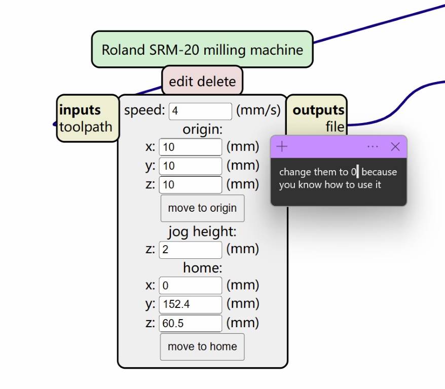
- origin means offset from the real origin position,so set it to (0,0,0).
jog height is the safe distance when millend move without milling.
home is the veiw position when milling work done where the mill will go.
- Delete this websocket device module because we will not connect to Roland directly.
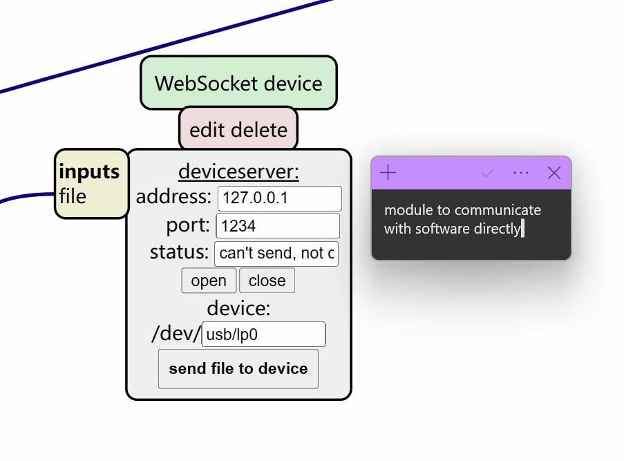
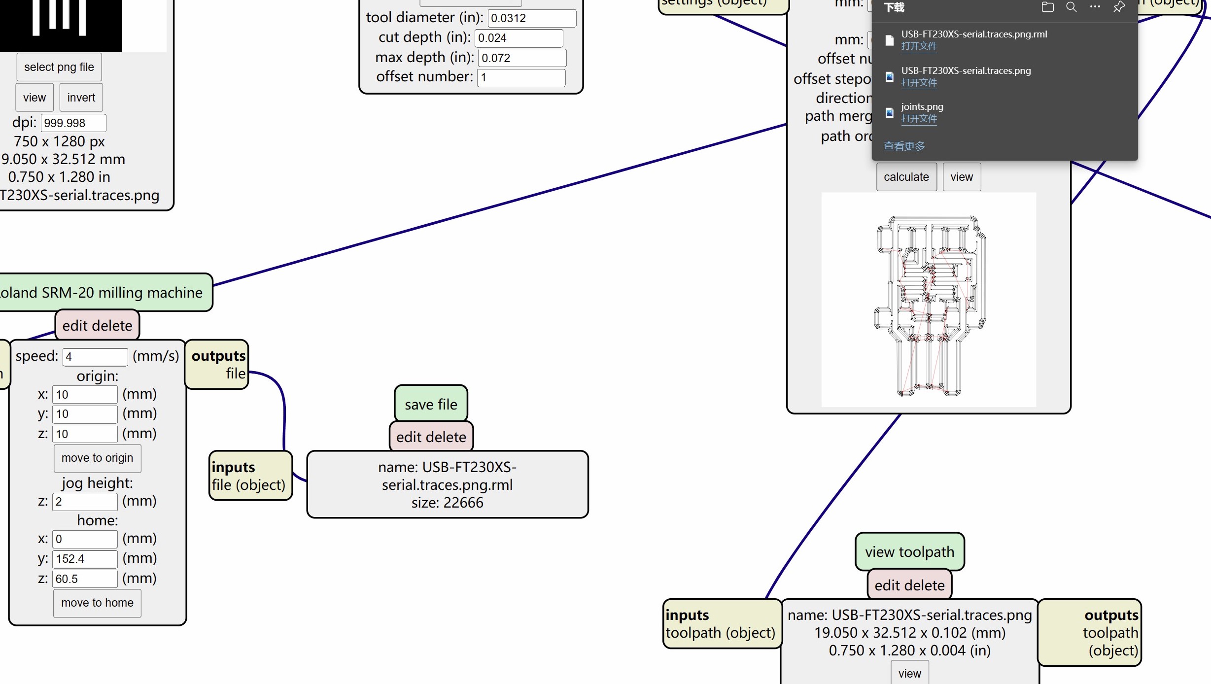
- Add a new module via right click -> modules -> open serve module -> file -> save, and link the inputs of it to outputs of Roland SRM-20 milling machine
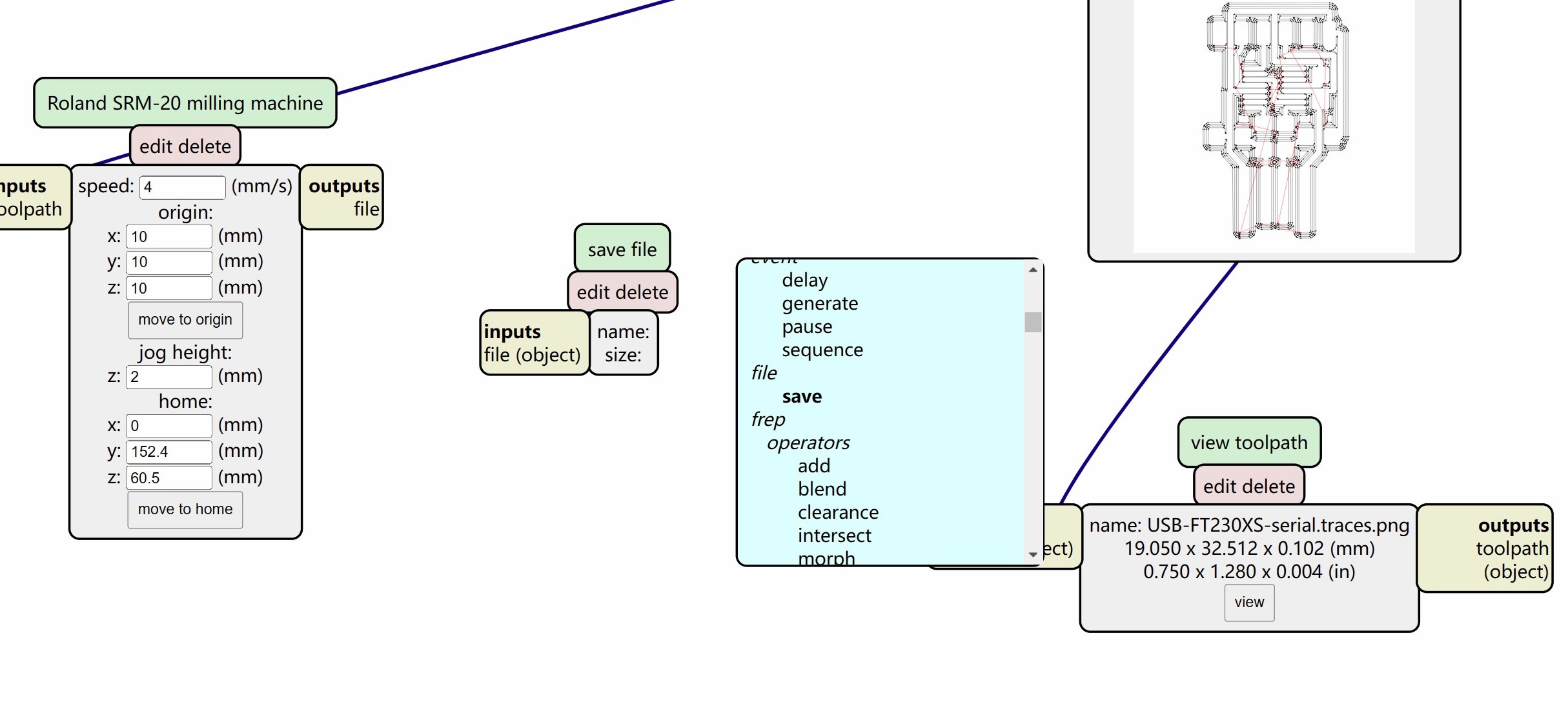
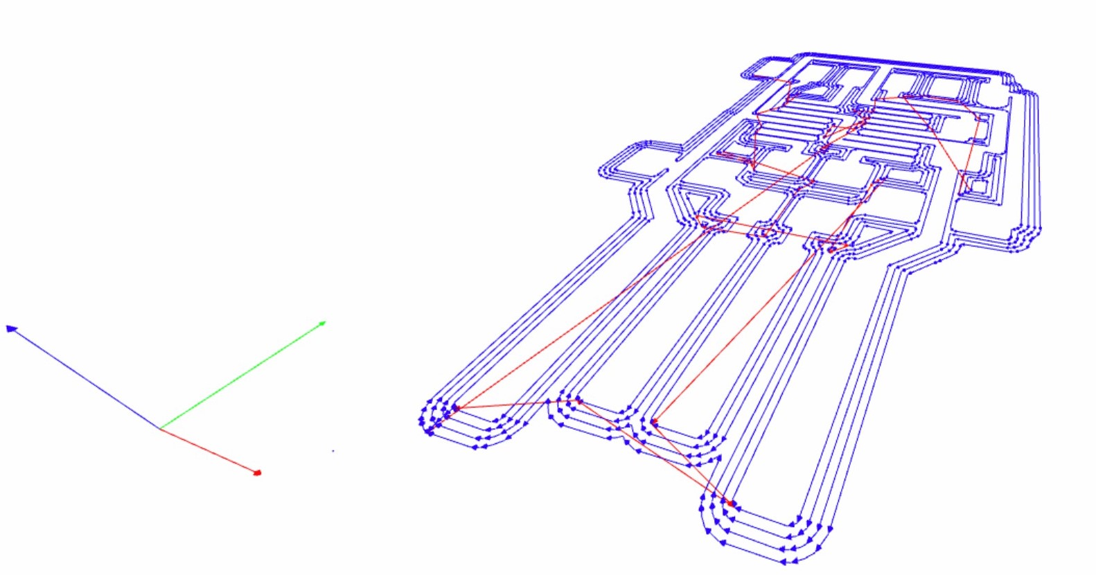
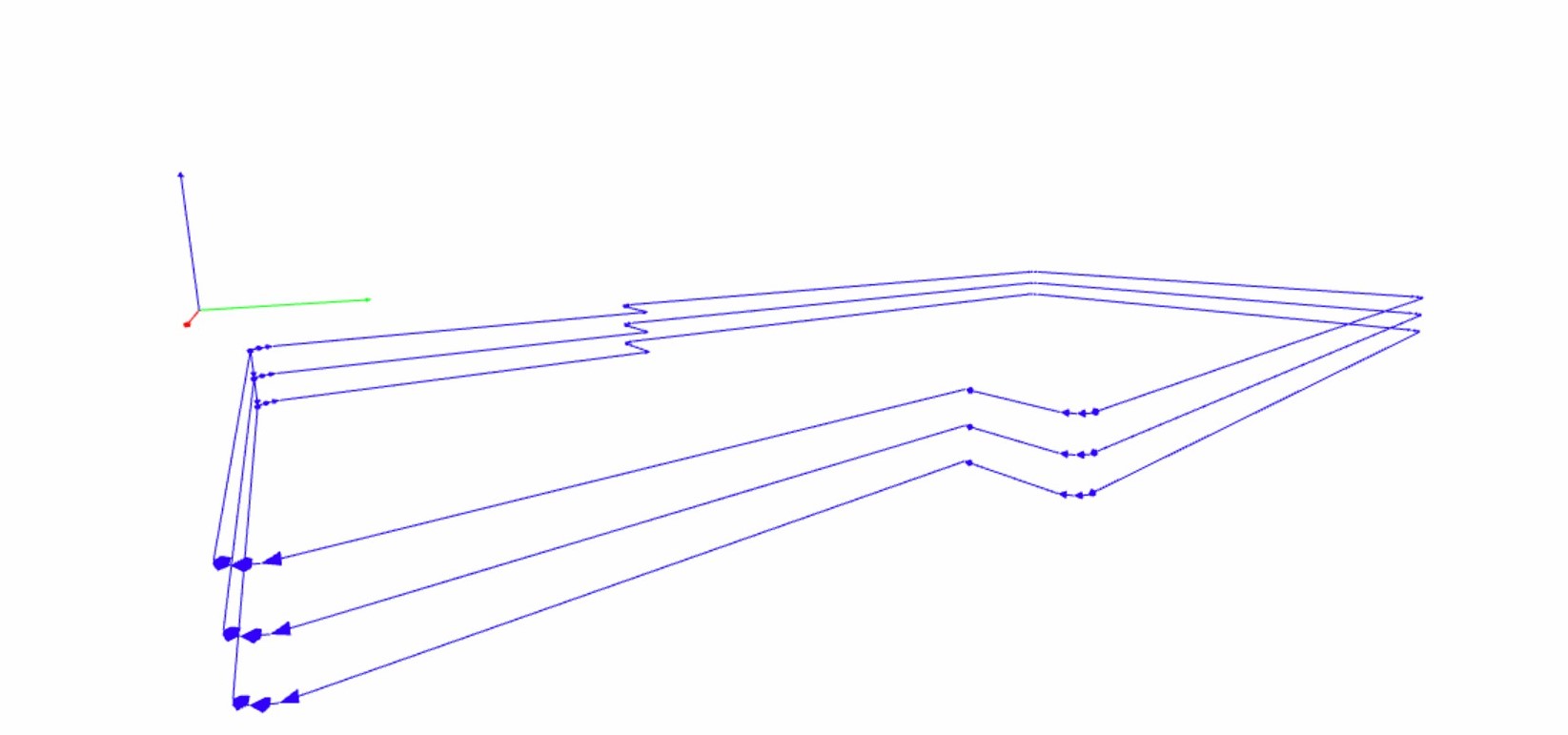
- Click calculate in the mill raster 2D, and you will get a file end with .rml and preview of toolpath.
- Trace and outline&hole need different setting, PLZ make sure if you set the right parameter after import other png file.
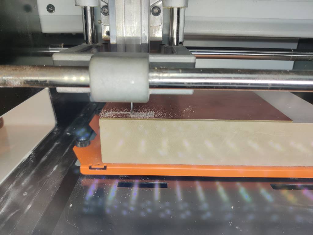
Start milling
About how to operate the Roland SRM-20, pleace go to check our group assignment via here.
And special thanks to @Alisa (2021 fabacademy student in O Shanghai), She took some nice shots of how to planish the plane and how to fix the material on the plane!
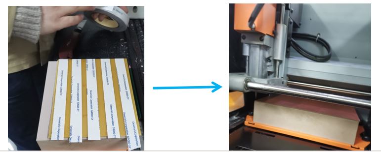
Make sure your workbench is clean and flat. If not, choosing the surface cutting to planish the plane.
Paste your materials to the workbench with the double-side tape and keep it very very flat without any bubbles or dust. The time spent on the process is much valuable as you will receive one accurate production. The double-side tape should be easy to take away to make sure the surface of Copper is flat.
Some pictures and brief intro about my work
- Don’t forget to choose the right endmill. 0.4mm for trace, 0.8mm for hole and outline.
- Start milling with a low speed. Then speed up when you make sure it dosen’t make mistake. And if you have tine traces, KEEP slow is better.
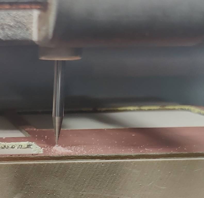
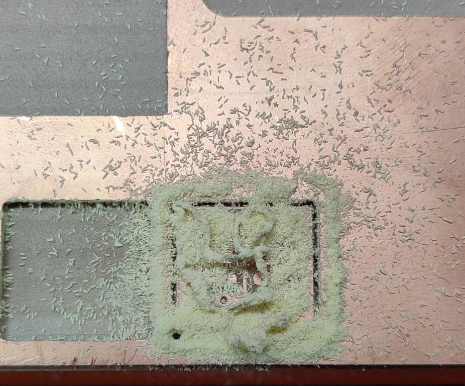
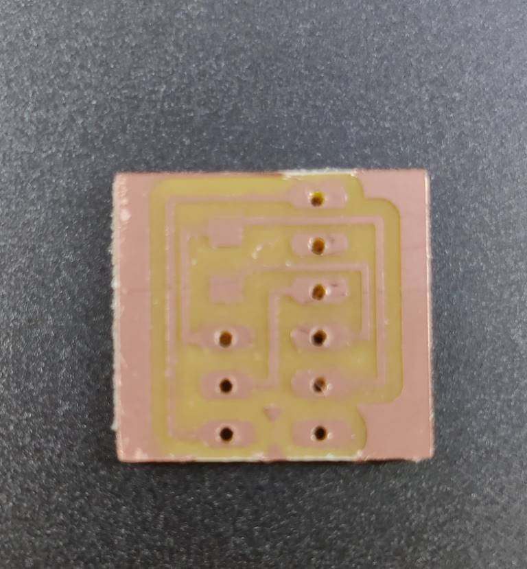
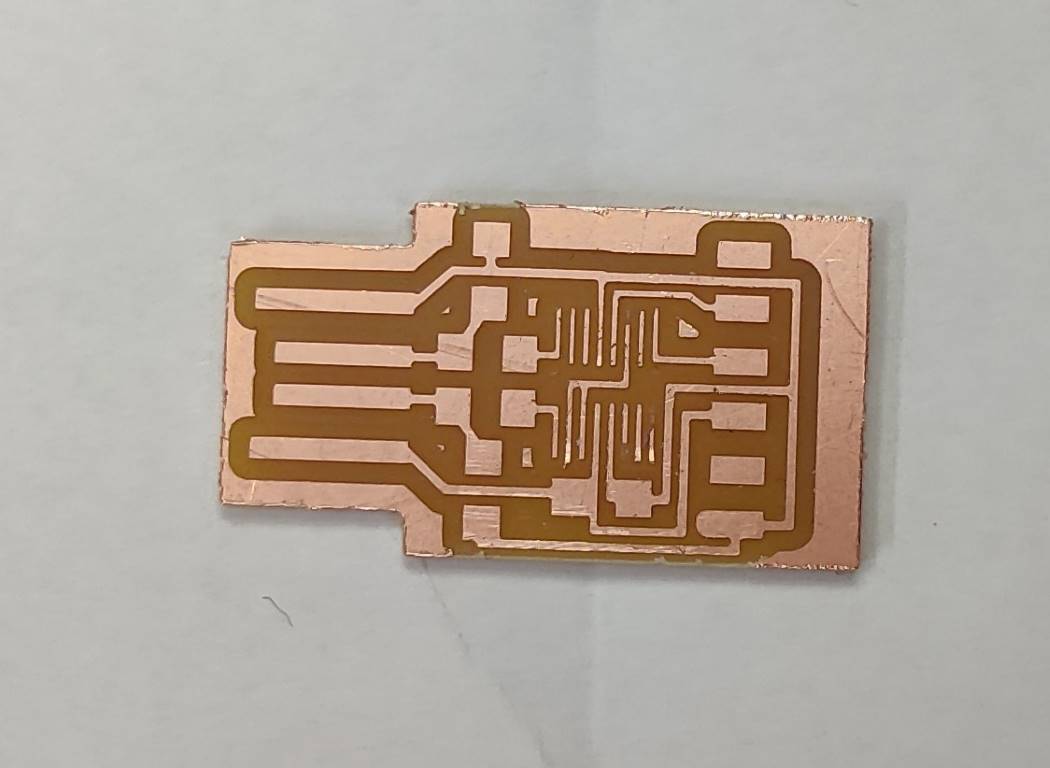
- Mill finished.
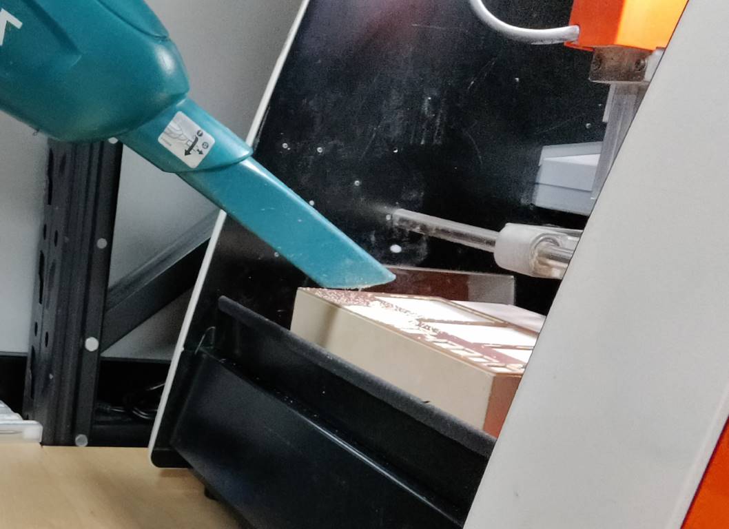
- Clean with vacuum cleaner
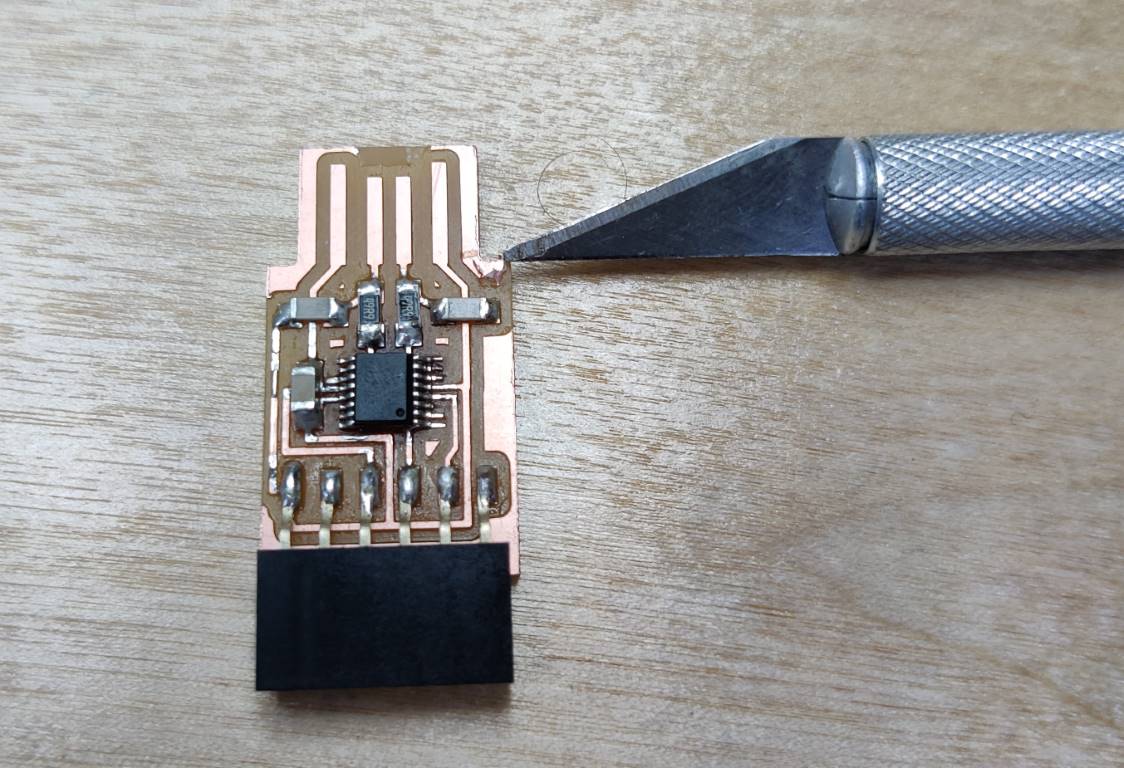
- Try to move it carefully with scraper’s side (don’t use the edge)
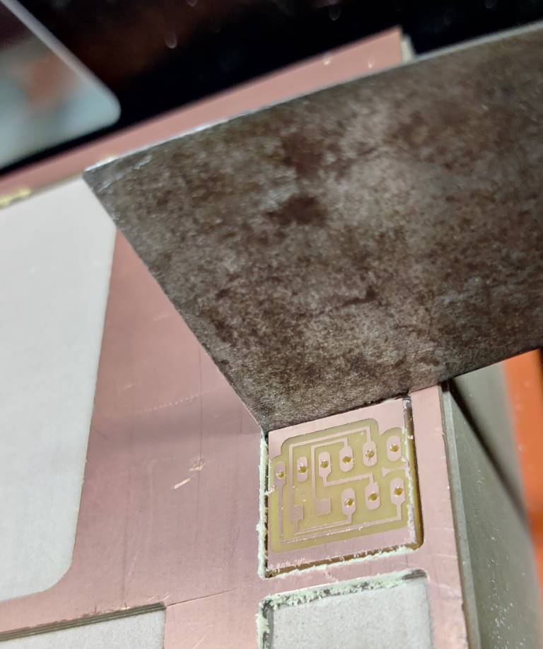
- Then you get you PCB board down
- The same way to make the other board
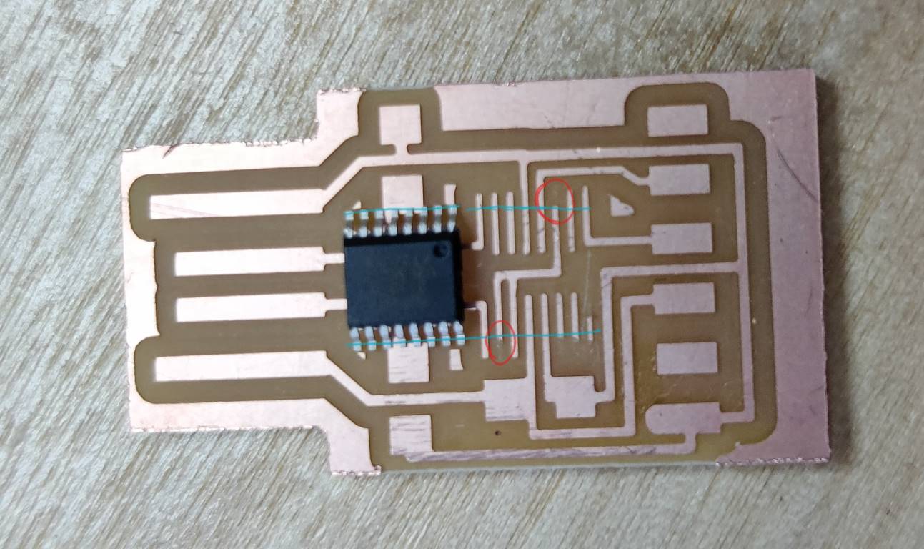
 A problem with my trace/ The trace to soldre the chip is so thin. When I used 100% speed, it is almost broken.
After I told Saverio this, he said 4mm/s is better (50% speed of our machine)
Soldering
I am familiar with soldering, except soldering SMD.
Here I find a nice site to learn soldering: click here
And speak of SMD soldering, Saverio showed us how to do it, and also explain it with a nice video in Youtube, and…prepare some material for us to practice.
To solder the resistance or capacitance is not difficult, and the trick is…
- iron in, wait, solder in. solder out, wait, iron out
- iron in, wait, resistance in. iron out, wait, tweezer out
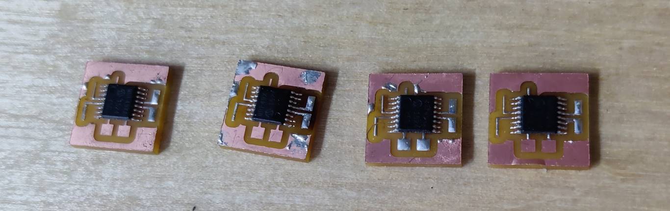
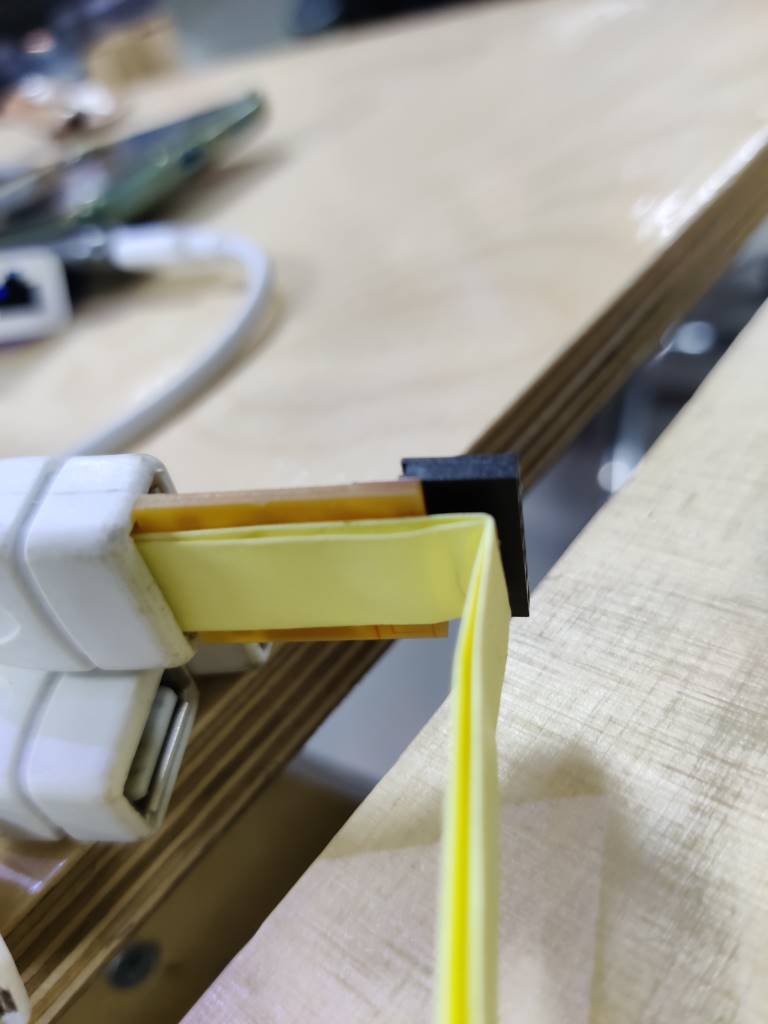
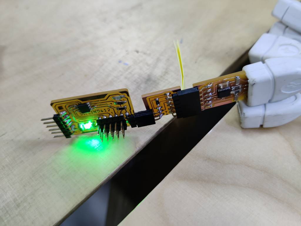
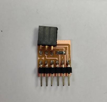
Here is my soldering work USB.serial-UPDI converter (not good soldering I think… But still work well)
But! to solder a chip which has tiny legs is a challange.
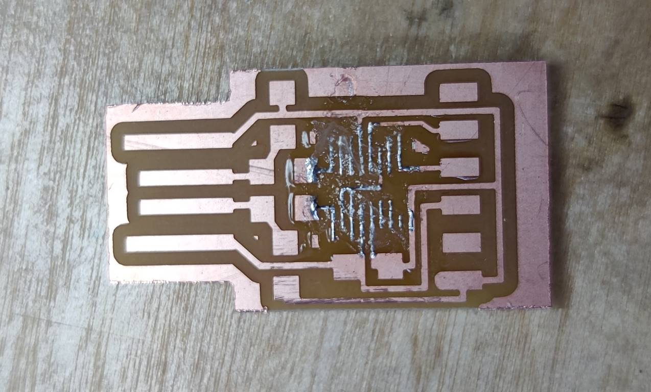
I tried to solder it with following Saverio and the video I post before, but failed so many times with solder on board gathering and become bubbles.
Saverio told me that it is because the way we soldered is adapted to the PCB board which is made by manufactory. The solder should stay on the copper instead of gathering in the gap like we did, because our board is made by CNC.
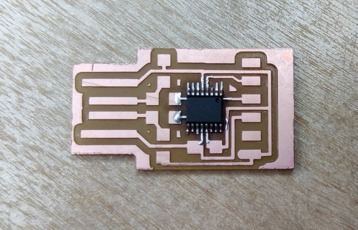
So, after trying many times and, eventuallly, luckily, find a best way to solder the chip on our own board.
Here is the trick…
- 0