Group Assignment
Division of Labor
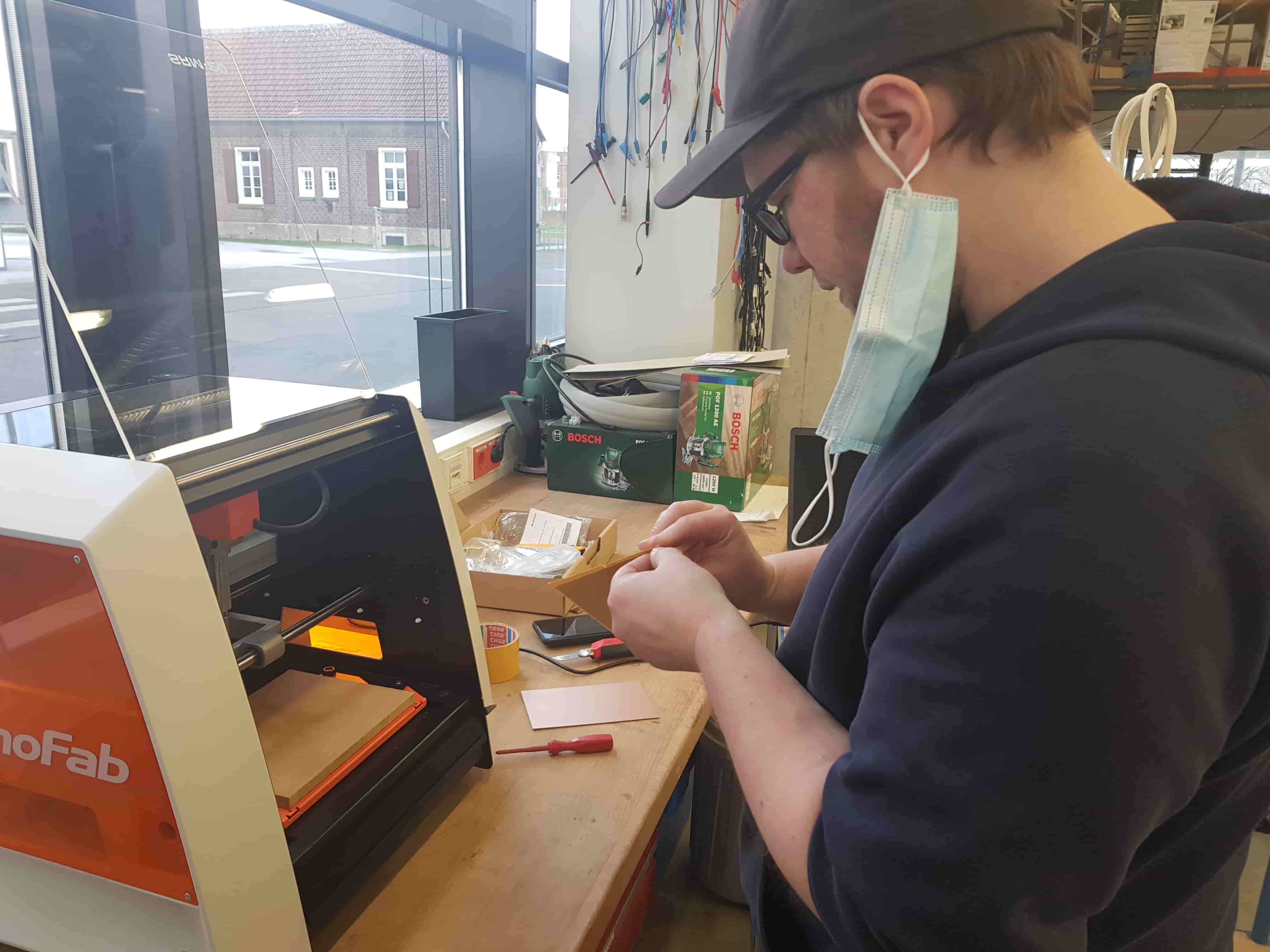
We wanted to cut the line-test shown by Neil on both machines. Aaron had a lot of success with the Genmitsu so he took over most of that mission while Roland took on the Roland. Leen was bouncing back and forth with Marcello, helping with the tests on both machines.
Playing with the Genmitsu
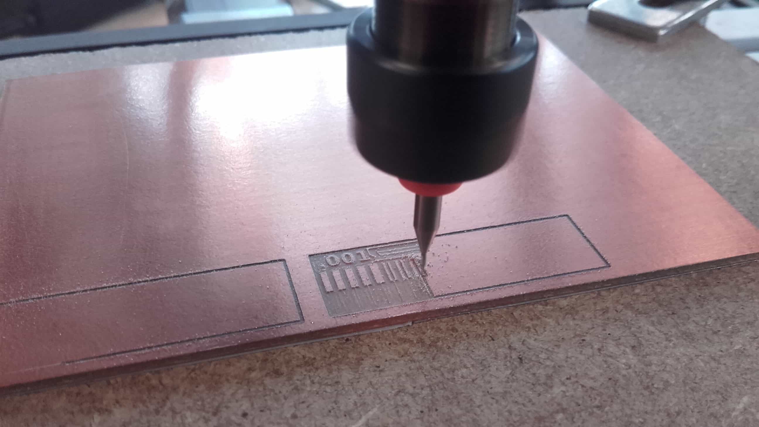
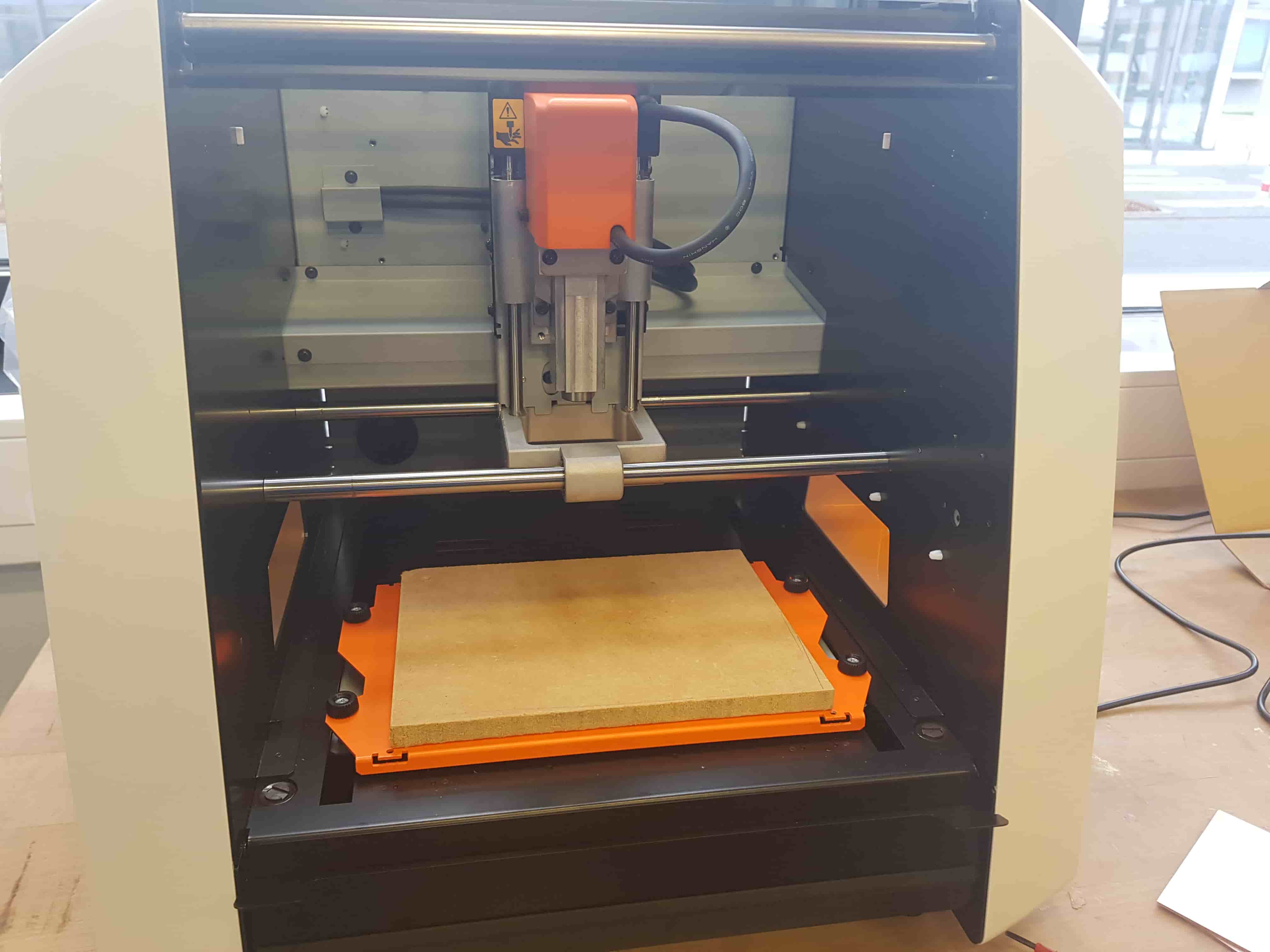
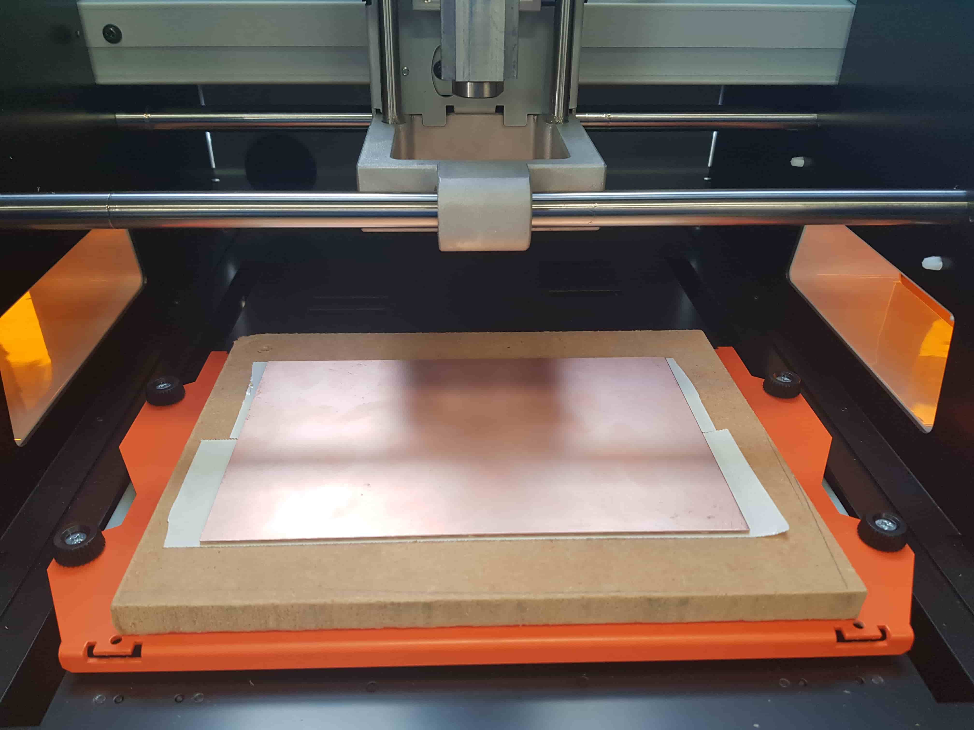
Preparing the Board for Cutting
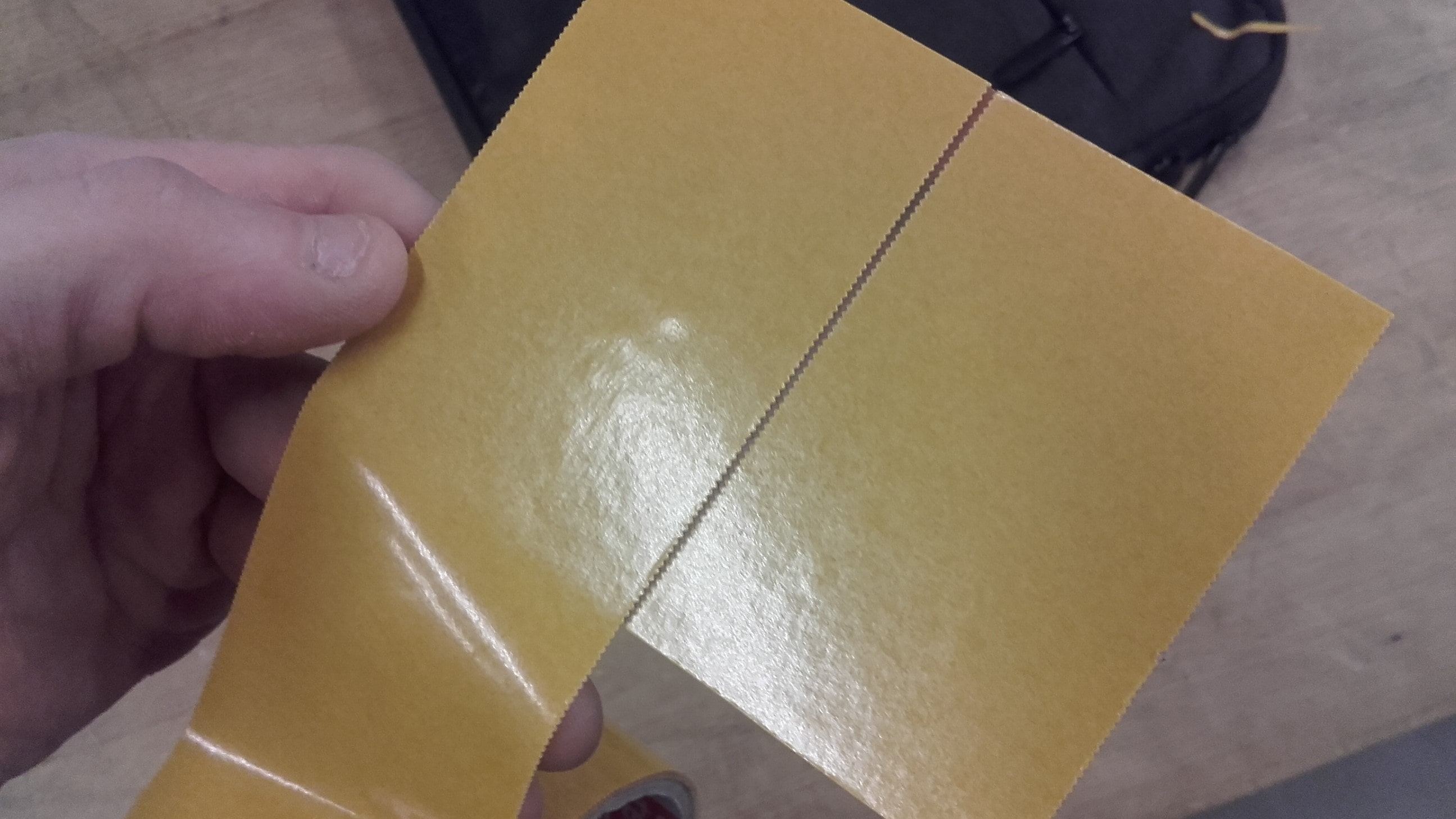
To prepare the board for cutting, we used a fresh piece of sacrificial MDF and taped the board to it using double-sided tape. We tried to be very careful to avoid bubbles or varying the thickness of the tape at all.
MODS
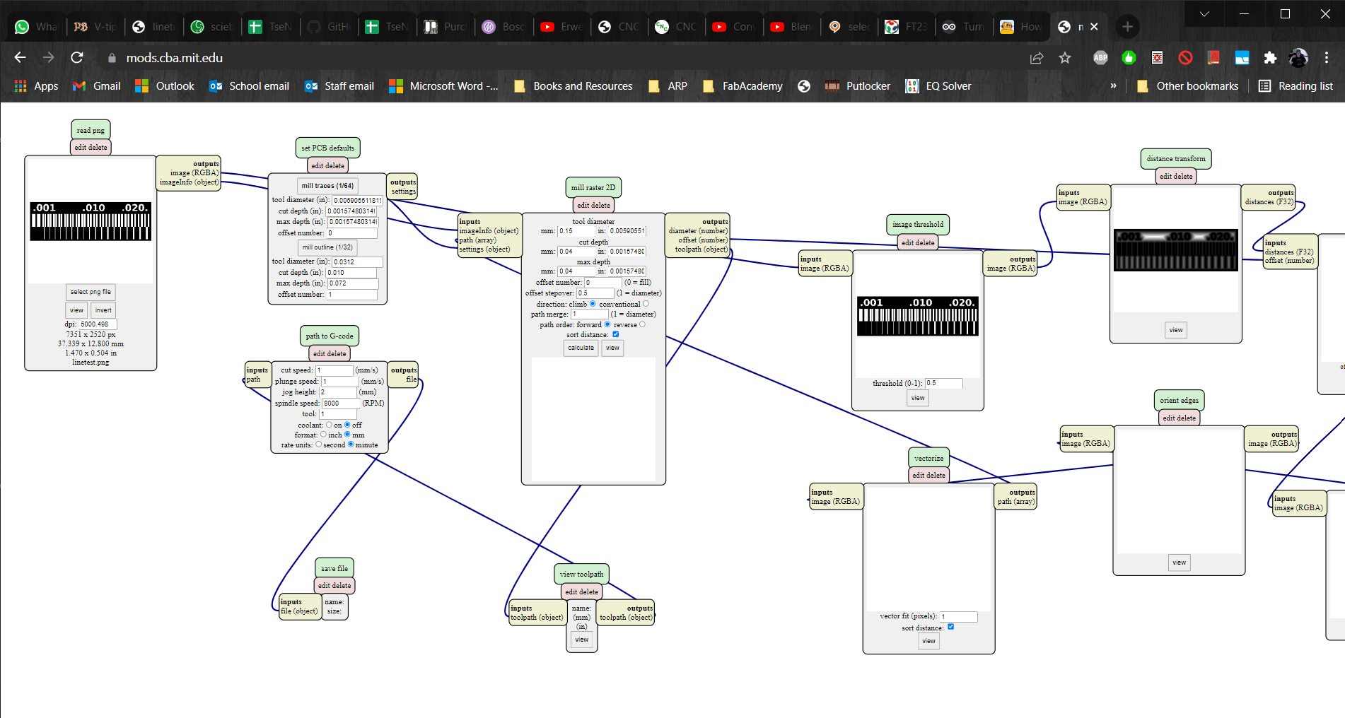
We decided the first linetest would be cut using the same parameters that had been successful when cutting the PCBs the day before. The only difference was to try using a 0.12 mm tool instead of a .23 mm one. We opened up MODS and filled the fields accordingly.
Candle
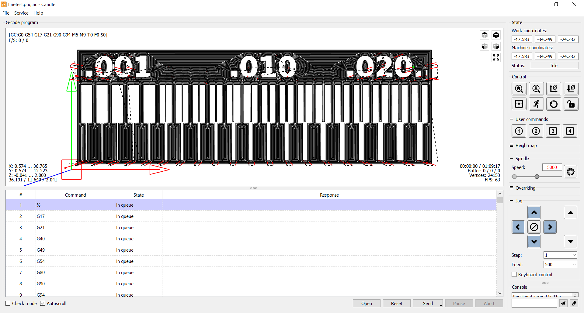
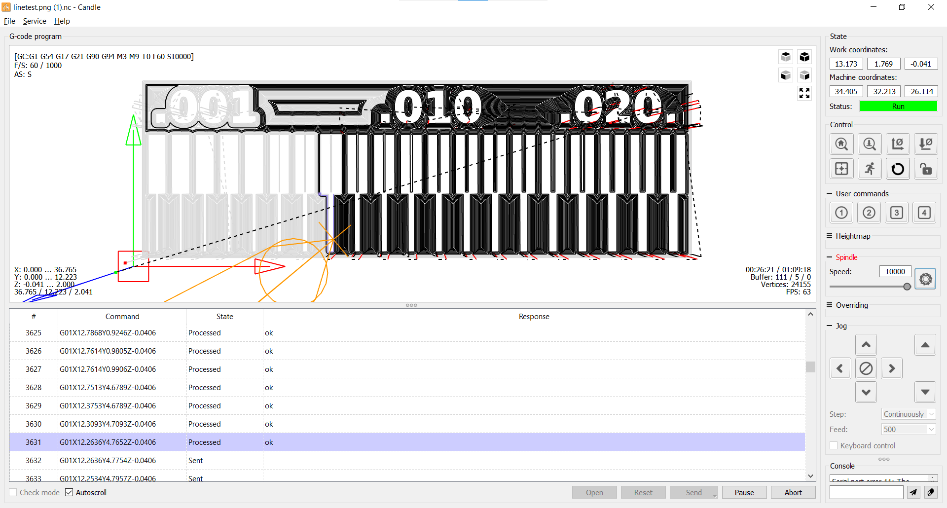
Then the gcode was exported from MODS and imported into Candle.
Problem
On the very first pass after sending the gcode to the Genmitsu, we noticed a problem. This is when we discovered that these boards are usually sheer-cut, and that you cannot trust the dimensional accuracy of the thickness if you get too close to the edge.
g0, x0, y0
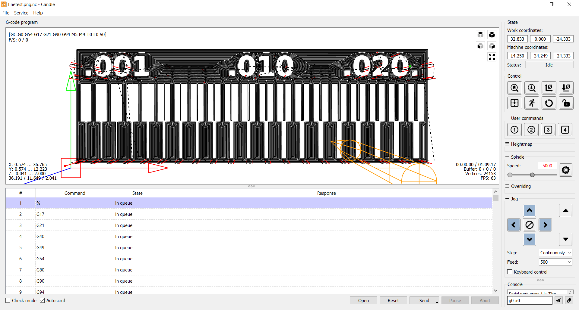
This is when Marcello taught us a particularly useful bit of gcode: the typing "g0, x0, y0" will automatically send the device back to whatever origin you have established. Definitely good to know for situations like this.
So Far...
We resent the gcode after creating a new orgin...
...So Good
...and everything was going well.
Frozen
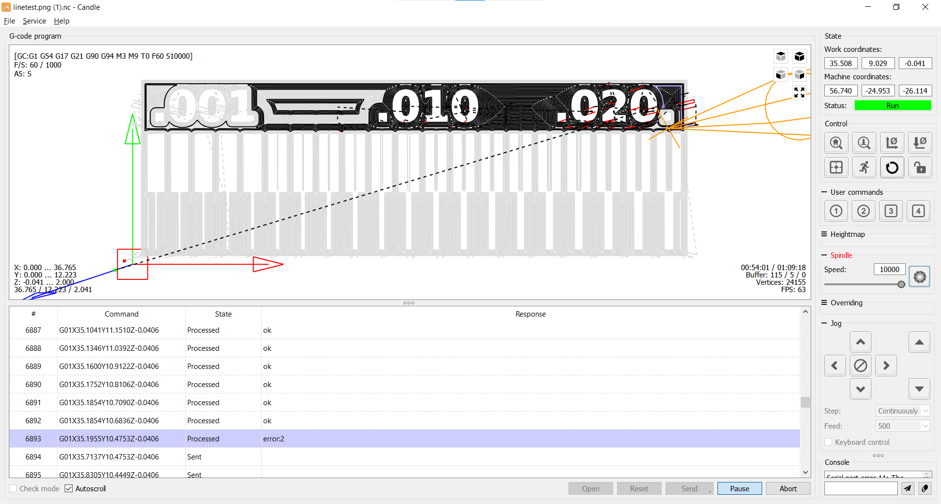
Until the USB cable got bumped and froze the machine. We collectively tried to get it to continue cutting, but the mill was stuck in one place, and the Candle GUI was completely frozen.
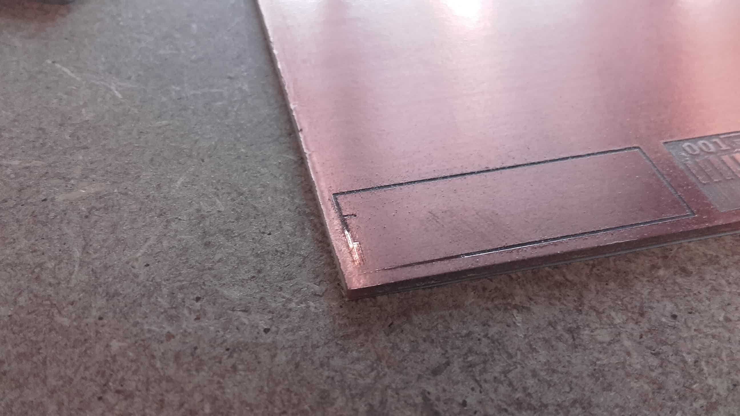
Results
Fortunately, the test was more or less completed before the mill went offline. Only some non-essential text was not cut.
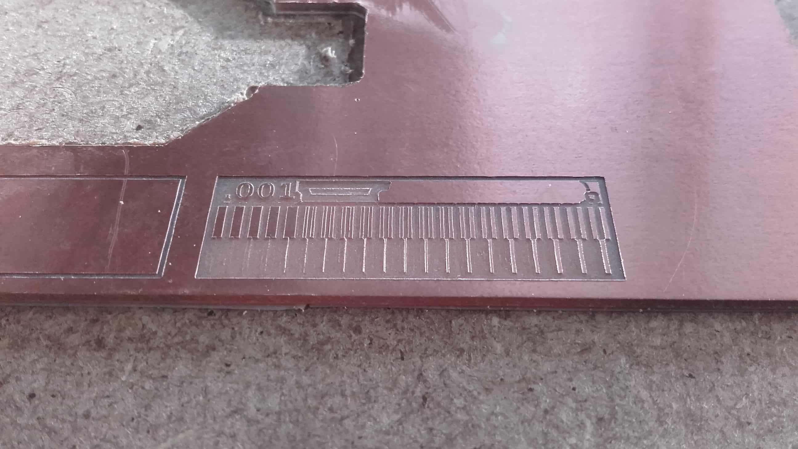
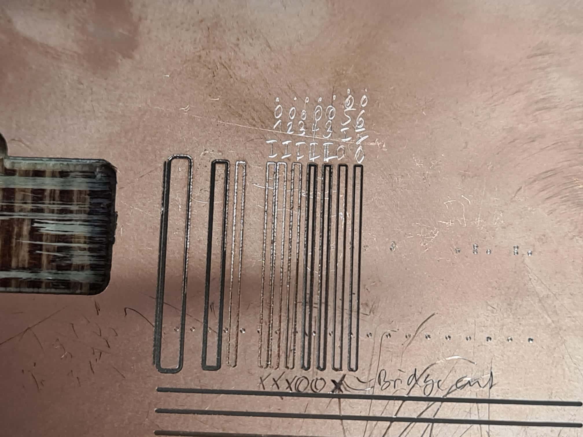
Analysis
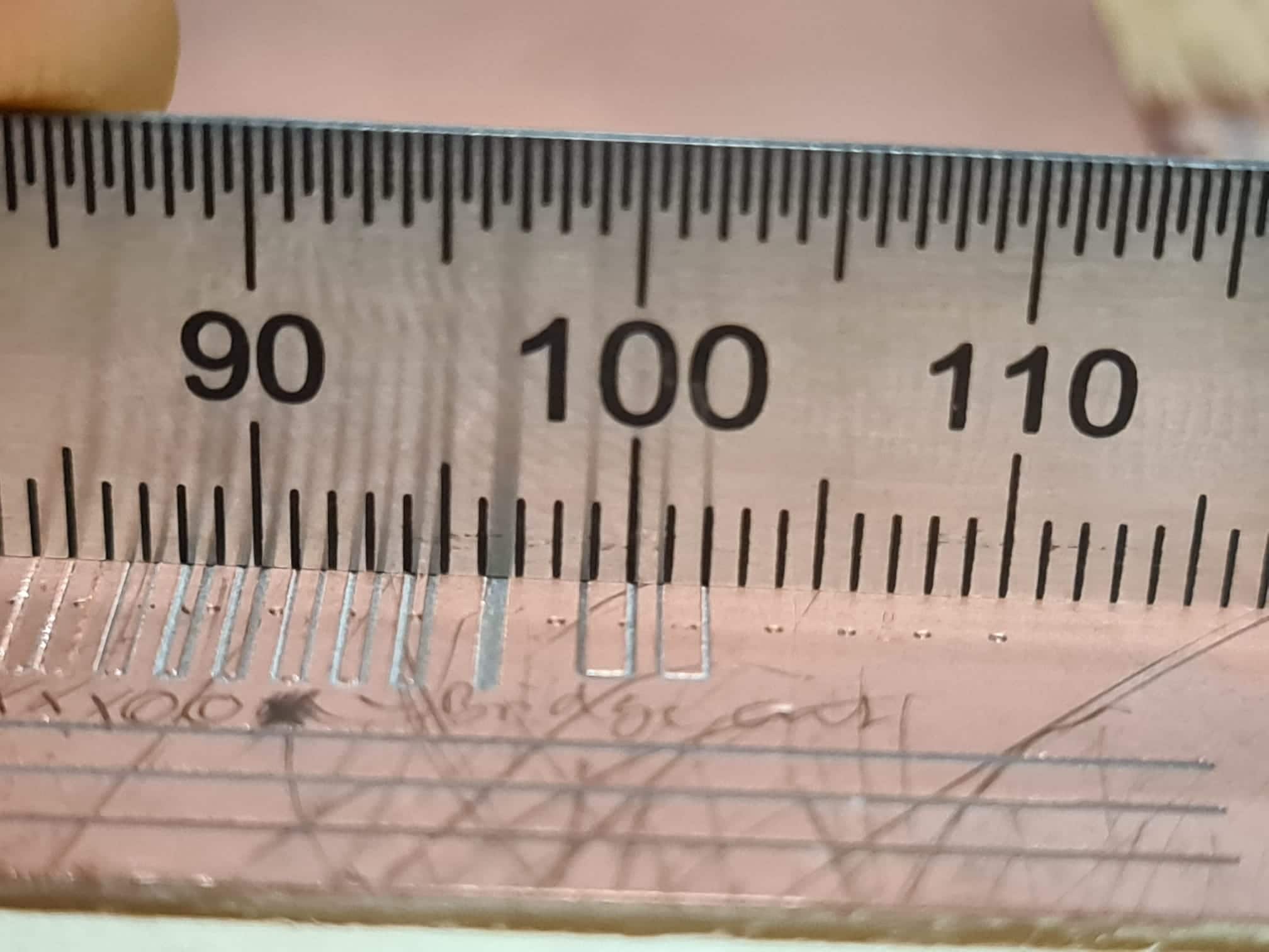
As you can see from the image, the result definitely leaves something to be desired. The female slots cut well enough, but the first usable trace is approximately 200 microns wide. After the excellent results form the Genmitsu the day before, we were all surprised that the quality of the cut was not better. It is not clear what caused the difference in quality compared to the day before, but since using the smaller tool was the only thing we changed, we assumed it had to be that. It is possible that the thinner tool flexxes more under the cutting load, or even that the tool was broken when we used it but we did not notice. We would like to do more testing on the Genmitsu, but time did not allow it this week.
Figuring Out the Roland
Preparing Test Files and Other Reasoning
- First, we tried using Roland Clickmill to simply mill lines at different depths without going through Mods for generating Gcode repeatedly
- Unfortunately, while first promising, this produced - again - very weird results and was pretty much unusable
- We then created a 1 mm by 20 mm black rectangle with 0.25 mm corner radii in Inkscape, selected it and exported the selection (so just the rectangle at 1500 dpi resolution (this is file "1 x 20 mm trace, black, no padding")
- This was loaded into mods for the first few trial runs until, when we tried verifying 0,2 mm was the proper tool diameter to set for our tool - this isn't entirely clear due to the V-shaped tip
- Traces were completely removed when we enlarged the tool diameter to 0.4 mm (what should have happened was that the copper stayed the same, just more material should have been removed on the outside of the cut)
- We then added a 1 mm padding on each side of the rectangle in Inkscape and changed the background color of the page in Inkscape to white (standard is transparent, not white!)
- We then exported the whole page (a 1 x 20 mm black rectangle centered on a 3 x 22 mm sized page) as PNG @ 1500 dpi (this is file "1 x 20 mm trace, white, 1mm black padding on all sides")
- When loaded into this would still cut away the wrong part of the copper, so the image was inverted in Mods, leaving a white rectangle centered on a black background
- This would then correctly cut on the outside of the white areas, leaving the white area behind even when choosing a tool with a larger diameter or more offsets
- Since the copper material left behind when cutting with an assumed tool diameter of 0.2 mm was exactly 1 mm, as designed, it was assumed that 0.2 mm must be the correct tool diameter at the penetration depth of 0.05 mm.
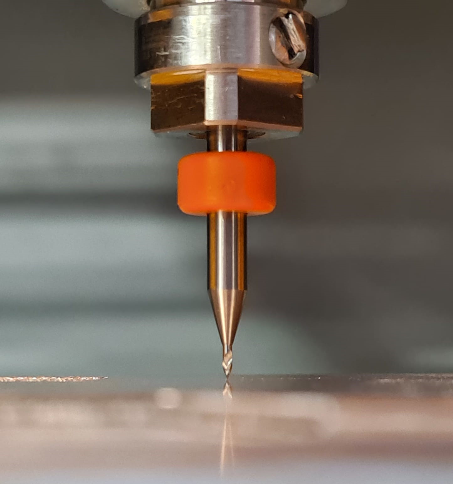
Zeroing the Z-axis
- We opted for zeroing the Z-axis physically this time (this procedure is also described in the SRM20 manual)
- for doing so, the Z-axis (with a tool in the collet) was driven down carefully until nearly touching the PCB (about 1.5 - 2 mm distance, still)
- At that height, the set screw of the tool was loosened while holding the tool so it wouldn't drop freely. When loose, the tool was slowly lowered onto the PCB surface
- With the set screw still loose and the tool resting on the PCB surface, the z-axis was moved down another 1 - 2 mm, pushing the tool further into the collet in the process
- The set screw was then carefully tightened again, making sure not to lift the tool up
- The z-axis was then zeroed in the software, with the tool tip resting directly on the surface, but not penetrating yet
Results from the Roland
Default
| Test ID | Speed in mm/s | Input PNG | Tool Diameter | Cutting Depth | Offsets | Notes |
|---|---|---|---|---|---|---|
| #1 | 4 | 1 x 20 mm trace, black, no padding | 0.2 | 0.01 | 1 | Copper not cut all the way through |
| #2 | 4 | 1 x 20 mm trace, black, no padding | 0.2 | 0.02 | 1 | Copper not cut all the way through |
| #3 | 4 | 1 x 20 mm trace, black, no padding | 0.2 | 0.03 | 1 | Copper not cut all the way through |
| #4 | 4 | 1 x 20 mm trace, black, no padding | 0.2 | 0.04 | 2 | Copper cut all the way through and isolated |
| #5 | 4 | 1 x 20 mm trace, black, no padding | 0.2 | 0.03 | 2 | Copper also cut all the way through and isolated, doesn't look to convincing though… |
| #6 | 4 | 1 x 20 mm trace, black, no padding | 0.2 | 0.05 | 1 | Isolated after cutting leftover bridge at bottom |
| #7 | 4 | 1 x 20 mm trace, black, no padding | 0.2 | 0.06 | 1 | Isolated after cutting leftover bridge at bottom |
| #8 | 4 | 1 x 20 mm trace, black, no padding | 0.4 | 0.05 | 2 | Copper completely gone, noticed here that I had the colors the wrong way around. Changed file by adding 1 mm of padding around the trace and inverting in Mods |
| #9 | 4 | 1 x 20 mm trace, white, 1mm black padding on all sides | 0.2 | 0.05 | 2 | Copper trace perfectly 1 mm wide as designed, cut shifted by 1 mm in y because of padding changing origin of Gcode |
| #10 | 4 | 1 x 20 mm trace, white, 1mm black padding on all sides | 0.2 | 0.05 | 1 | Copper trace perfectly 1 mm wide as designed, isolated but looks a bit riskier than 2 offsets |
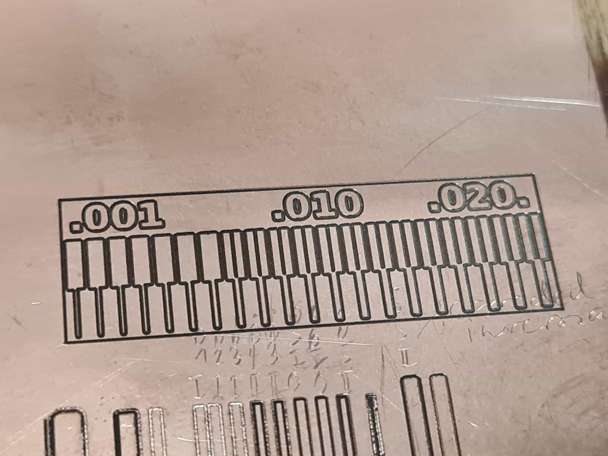
| #11 | 4 | LineTest | 0.2 | 0.05 | 1 | Very nice result, crisp edges, good cutting, first gap at 0.008, first line (0.001) visible and seems continuous! |
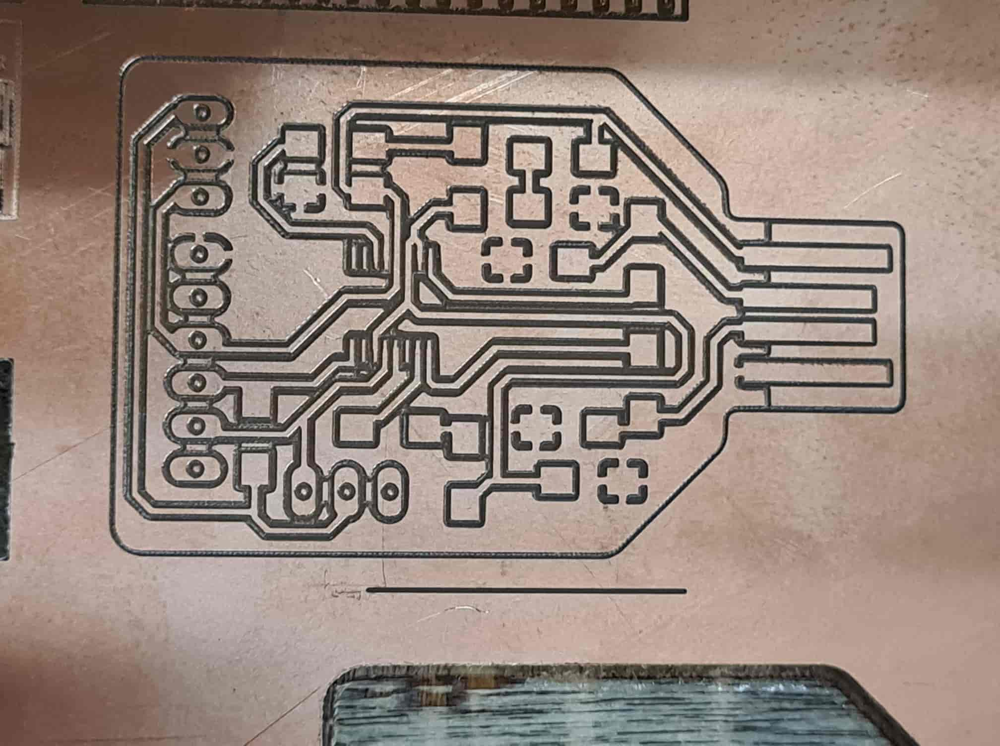
| #12 | 4 | FTDI USB Programmer | 0.2 | 0.05 | 1 | Board is mostly good, but copper not cut all the way through in some areas (maybe PCB is not totally flat) |
| #13 | 4 | FTDI USB Programmer | 0.2 | 0.05 | 2 | Reran test ID # 12 in-place, just with 2 offsets instead of one, which cleared out the remaining copper bridges |