9. Embedded programming
Assignments for week 8:
This week we have a group assignment and an individual assignment .
The group assignment for this week is to compare the performance and development workflows .
The individual assignment for this week is to read a microcontroller data sheet program my board to do something, with as many different programming languages and programming environments as possible .
The goal for this week is to try as many programming languages and to get to know how to read a data sheet in order to program a board and in my case the board I am going to program is the one we have made on Week 7 which is the “Hello world” .
Individual assignments::
Objectives:
- Read a microcontroller data sheet.
- program your board to do something, with as many different programming languages and programming environments as possible.
lets get familiar with “ATtiny44”
- Firstly, we have to get know what is a “ATtiny44 datasheet “:
Datasheets, are instruction manuals for electronic components, they explain exactly what a component does and how to use it.
-
First pages are usually a summary of the function and features of the component. You can quickly find a description of the functionality, the basic specifications (numbers that describe what a component needs/can do and sometimes a functional block diagram that shows the internal functions).
-
“”Pinout”“ lists the (component’s pins, their functions, and where they’re physically located on the component ).
Pin configurations And Pin descriptions :

| Pin | Function |
|---|---|
| VCC | Supply voltage |
| GND | Ground |
| RESET | Reset input. A low level on this pin for longer than the minimum pulse length will generate a reset, even if the clock is not running and provided the reset pin has not been disabled. Shorter pulses are not guaranteed to generate a reset. The reset pin can also be used as a (weak) I/O pin |
| Port B (PB......PB0) | Port B is a 4-bit bi-directional I/O port with internal pull-up resistors (selected for each bit). The Port B output buffers have symmetrical drive characteristics with both high sink and source capability except PB3 which has the RESET capability. To use pin PB3 as an I/O pin, instead of RESET pin, program (‘0’) RSTDISBL fuse. As inputs, Port B pins that are externally pulled low will source current if the pull-up resistors are activated. The Port B pins are tri-stated when a reset condition becomes active, even if the clock is not running. |

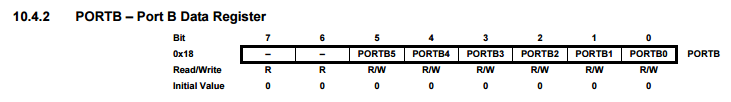
The images above is the Data Direction Register for port B. In the top row, you have the bit numbers. These are effective location designations. Binary is read from right to left, hence the backwards numbering. There are 8 bits in this register, from 0 to 7. The second row, is the name of the ports in the register. Note that there are two bits that don’t have names. They do not do anything. By the end, these are the names you will use when referencing the various bits in a register. The third row tells you if you can read the bit, write the bit, both, or neither. Bit 6 and 7 do not have a port name, do not do anything, and therefore cannot be written to. All other bits can be read from and written to. The fourth row tells you what each bit initializes to. In this case, they are all 0s.
There are a total of 6 usable bits, going from 5 to 0, or 0 to 5. Either is acceptable. You may see it referred to like this: DDRB[5,0] or DDRB[0,5].
Shown on the bottom of page 54, it states that a 0 for anyone of these writes the port (and therefore its corresponding pin) as an input. A 1 writes the port as an output. So this is the first thing we want to do in replacing a digitalWrite() command, by replacing the pinMode() command. Before showing you what the actual coding looks like, we will skip to the next register to continue with understanding what to do.
Port A (PA7…....PA0) | Port A is a 8-bit bi-directional I/O port with internal pull-up resistors (selected for each bit). The Port A output buffers have symmetrical drive characteristics with both high sink and source capability. As inputs, Port A pins that are externally pulled low will source current if the pull-up resistors are activated. The Port A pins are tri-stated when a reset condition becomes active, even if the clock is not running. Port A has alternate functions as analog inputs for the ADC, analog comparator, timer/counter, SPI and pin change interrupt.
maximum ratings :

The image above shown what is the maximum ratings for the component that if I crossed it will be damaged.
Fuses [ permanent storage in the chip ]
fuse low byte
fuse high byte
fuse extended byte
These bytes are called fuses and can be reprogrammed as many times as you want and determines the behaviour of the chip. To do that, their value is not erased when the chip is powered off or reprogrammed.
Each microchip has its own definition for the values that must have the fuses and we are going to work with the fuses of the Atmel Attiny44A.
To get know the types of the Fuses for the Attiny44A Download this file
Fuse Calculator For using the fuse calculator you need to download this folder (right click on the link and “save as”)and open the html inside.
Programming :
to do that I had to research how to program an ATTINY and here is the process
let’s start :
We will start with Downloading Arduino IDE
Adding the ATTINY library using Windows :
After successfully downloading “Arduino IDE” you have to download the “Attiny Library” and for I have used the “Attiny44” and here is how to do it :
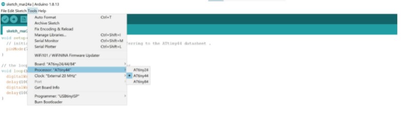
First open Arduino IDE and go to Files>> Preferences, And this window will appear :
You have to download all the “Drivers” and “Tools” and I will list them one by one so you can get them easily.
for upload a blink code using “IDE” using Windows I followed Hani tutorial tutorial.
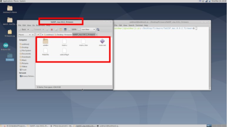
Programming with Linux:
Steps you have to type it in the command:
-
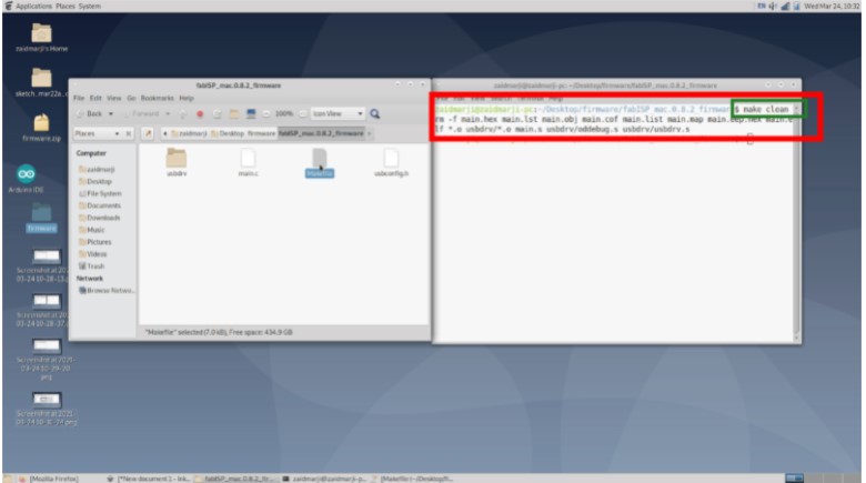
Make clean: to switch between Hex and Binary.
-
lsub: To see what Usb is connected with your device and if there’s any problem with connection.
-
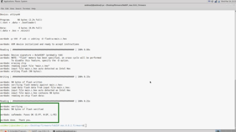
make program-fabISP :(as I named the project)
makefile:
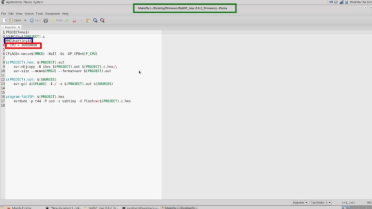
Makefile defines some settings and commands used to program the ATtiny44. The Makefile code below stores ceramic resonator speed, project name, programmer, target board, lfuse value and two commands used to program ifuse (program-avr-fuses) value and upload hex file (program-avr).
To create my makefile, I used Neil’s example and then edited it to have the following:
          PROJECT=ammar_eco
           SOURCES=$(PROJECT).c
           MMCU=attiny44
           F_CPU = 20000000
           CFLAGS=-mmcu=$(MMCU) -Wall -Os -DF_CPU=$(F_CPU)     #create set of parameters for the compiler (clock, MCU)

           $(PROJECT).hex: $(PROJECT).out
         avr-objcopy -O ihex $(PROJECT).out $(PROJECT).c.hex;\      #copy and translate object files
         avr-size --mcu=$(MMCU) --format=avr $(PROJECT).out         #size utility lists the section sizes

           $(PROJECT).out: $(SOURCES)
         avr-gcc $(CFLAGS) -I./ -o $(PROJECT).out $(SOURCES)        #to compile the file

           program-fabISP: $(PROJECT).hex
         avrdude -p t44 -P usb -c usbtiny -U flash:w:$(PROJECT).c.hex       #to upload the file

           program-fabISP-fuses: $(PROJECT).hex
         avrdude -p t44 -P usb -c usbtiny -U lfuse:w:0x1F:m         #to upload the settings of the fuses
1- Make clean: to switch between Hex and Binary.
2 lsub: To see what Usb is connected with your device and if there’s any problem with connection.
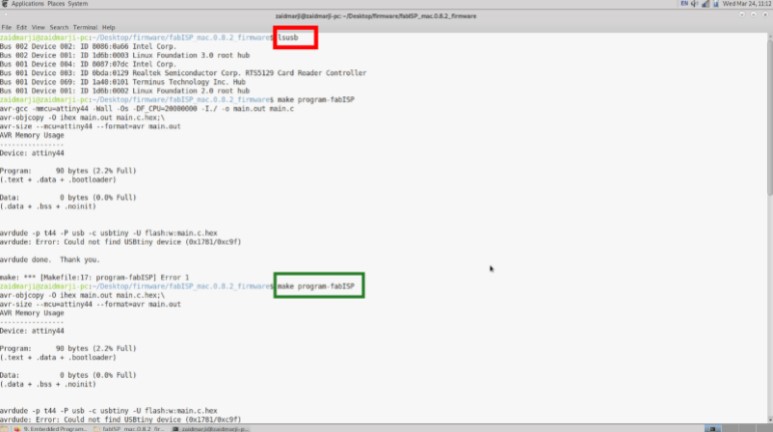
3- Make program-fabISP :(as I named the project)
Example Code
The code below toggles the output pins value when the push button is pressed. Writing logical 1 to PINA7 and PINA3 will toggle the output values on PORTA7 and PORTA3.
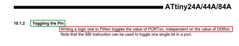
Sorce: ATtiny44 datasheet, page 55
#include <avr/io.h>
#include <util/delay.h>

int main(void) {
    //Clock divider set to one using lfuse bit CKDIV8 = 1

    DDRA |= (1 << DDA7); //Output: Red LED
    DDRA &= ~(1 << DDA3); //Input: Push button. Default = 1

    while(1){
        if(!(PINA & (1 << PINA3))){ //If push button pressed
            PINA |= (1 << PINA7);
            PINA |= (1 << PINA3);
            _delay_ms(250);
        }
        else{
            PORTA |= (1 << PORTA7);
            PORTA |= (1 << PORTA3);
        }
    }
}
Hero Shoot !

Group Assignment
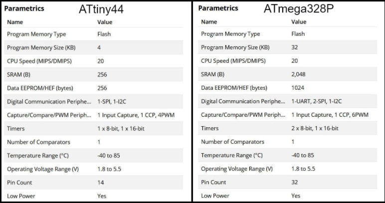
In this part we compared between two AVR families, ATtiny44 from tinyAVR family and ATmega328P from megaAVR family. For ATtiny44 we used avr-dude and FabTinyISP programmer and for ATmega328P we used Arduino UNO board.
Feature Comparison¶ The table below compares bwteen the two MCUs. “tinyAVR microcontrollers (MCUs) are optimized for applications that require performance, power efficiency and ease of use in a small package”, where “megaAVR microcontrollers (MCUs) are the ideal choice for designs that need some extra muscle. For applications requiring large amounts of code.” Source
Programming ATtiny44 using avr-dude:
Write the program in C language using Notepad++ text editor. In the Makefile, define settings like programmer, target MCU, clock rate and lfuse. Using “make” command, build the hex file to be uploaded to target MCU. Connect the FabTinyISP prorammer to USB and ISP cable between programmer and target board. Using the command defined in Makefile “make program-avr-fuses”, program the lfuse to target MCU. Using the command defined in Makefile “make program-avr”, upload the hex file to target MCU.
Programming ATmega328P Using Arduino UNO Board¶ Write code using Arduino commands. The target MCU should have the right bootloader burnt to be used on Arduino Uno board. Connect the board to USB and uplad the hex file. To butn a bootloader to a fresh ATmega328P, you can check the built in example from Arduino.
avr-dude Vs. Arduino:
Programming in C enables users to have more control and optimized execution. The code written in C occupies less memory than the code written in Arduino. Also, code written in C executes faster. Kepe in mind to program in C, the MCU should not have a bootloader burnt to it, which saves the flash memory needed for the bootloader.
The follwing codes blink a LED on pin PB0 in ATmega328P MCU. The first code using C language and avr-dude and the second using Arduion IDE
//Using C and avr-dude
#include <avr/io.h>
#include <util/delay.h>

int main()
{
    DDRB |= (1 << PB0);
    while(1){
        PORTB |= (1 << PB0);
        _delay_ms(500);
        PORTB &= ~(1 << PB0);
        _delay_ms(500);
    }
}
//Using Arduio IDE
void setup() {
  // put your setup code here, to run once:
  pinMode(8, OUTPUT); //PB0
}

void loop() {
  // put your main code here, to run repeatedly:
  digitalWrite(8, HIGH);
  delay(500);
  digitalWrite(8, LOW);
  delay(500);
}
After compiling both codes, we can compare memory usage. The image below shows the result after compiling both codes.
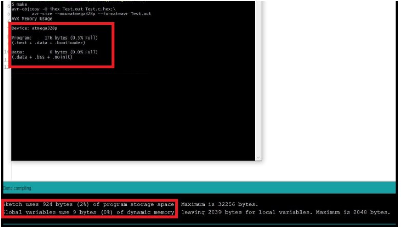
To summarize, the table below shows memory requiremets for both approaches. Note that in both codes the target MCU is ATmega328P.
| — | avr-dude C | Arduino IDE |
|---|---|---|
| Flash | 176 bytes | 924 bytes |
| SRAM | 0 bytes | 9 bytes |
Group Assignment
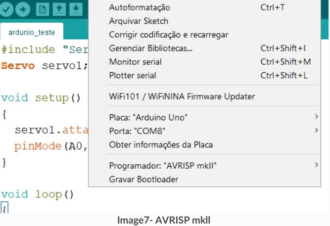
Programming in Arduino uno Configuration used for Arduino uno:
Board: Arduino Uno. Programmer: AVRISP mkll.
Programming
In this test, analog values were read from a joystick and transferred to a servo motor. First, I inserted the include “servo.h” to use the servo, then the analog port of the joystick was read and in the loop the association of the angulation from 0 to 180 is made with the analog port variation of 0. After having once the relationship is made, the position is passed on to the servo, with which the servo follows the position of the joystick.
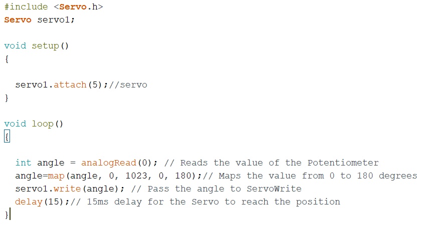
In this experiment it is possible to change the angulation of the servomotor using the potentiometer.

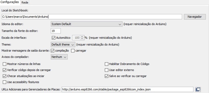
Programming the ESP8266 in the Arduino IDE Configuration Used for ESP8266:
Select preferences in files.

Added the ESP32 http://arduino.esp8266.com/stable/package_esp8266com_index.json
In tools, the card manager is selected.
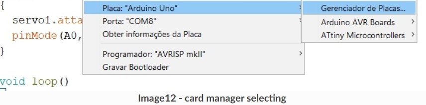
In the card manager after search for esp8266 click on install.

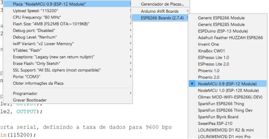
On tools and boards select the esp8266 model.
After configuring the IDE for ESP8266, I selected the ESP8266 WifiClient example in examples in the files section.
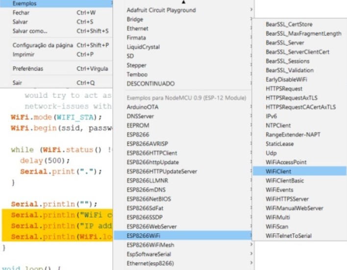
This example will establish a TCP connection for a “quote of the day” service. He sends a “hello” message and then prints the data received, it is only necessary to modify the ssid and password to make the connection. The Arduino serial displays the connection feedback.
 Image- esp8266
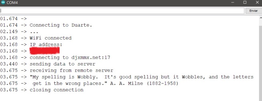 Image- TCP connection
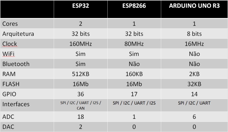 Image- comparison between ESP32, ESP8266 and Arduino UNO
Conclusion
The ESP32 is the most complete in terms of communication possibilities, with native Wi-fi and Bluetooth, and is more powerful, due to its more powerful hardware. As it has Wi-fi on the board it is easier to carry out projects, as it does not need any accessory to make the connection, in addition to having an easy programming using the Arduino IDE.