10. Input devices
Interfacing Ultrasonic Sensor With Arduino

An Ultrasonic Sensor is a device that measures distance to an object using Sound Waves. It works by sending out a sound wave at ultrasonic frequency and waits for it to bounce back from the object. Then, the time delay between transmission of sound and receiving of the sound is used to calculate the distance.
It is done using the formula ::
Distance = (Speed of sound * Time delay) / 2**
We divide the distance formula by 2 because the sound waves travel a round trip i.e from the sensor and back to the sensor which doubles the actual distance.
The HC-SR04 is a typical ultrasonic sensor which is used in many projects such as obstacle detector and electronic distance measurement tapes. In this tutorial I’ll teach you how to interface the HC-SC04 with an Arduino Uno.
Step 1: Components Required

To interface an Ultrasonic Sensor with an Arduino and view the distance on the serial monitor you’ll need:
-
Arduino Uno
-
HC-SR04 Module
-
BreadBorad
-
Jumper wires
You’ll need a laptop or a PC to upload code to the Arduino and view the Distance on the Serial Monitor.
Step 2: A Little About HC-SR04

The HC-SR04 is an ultrasonic ranging module. This economical sensor provides 2cm to 400cm of non-contact measurement functionality with a ranging accuracy that can reach up to 3mm. Each HC-SR04 module includes an ultrasonic transmitter, a receiver and a control circuit.
There are Four Pins on the HC-SR04. They are :
- Vcc (5V supply)
- Gnd (Ground)
- Trig (Trigger)
- Echo (Receive)
The key features to be noted are:
- Operating Voltage: 5V DC
- Operating Current: 15mA
- Measure Angle: 15°
- Ranging Distance: 2cm - 4m
Step 3: The Arduino Serial Monitor

The Serial Monitor is a part of the Arduino IDE. It is also available in the Web IDE. It allows you to send and receive data from the board connected via USB. This is using the concept of Serial Communication.
You can send the commands by typing in the window on the top and pressing ‘Enter’ or clicking ‘Send’. The data from the board is displayed below that.
This is very useful when debugging the code, or if you need to give inputs to the board, This is probably the most useful tool in the IDE. The more you use it, the better you get at testing complex projects that takes inputs and provides consequent outputs.
Step 4: The Circuit

The connections are as follows:
Vcc to 5V Pin of the Arduino. Gnd to Gnd Pin of the Arduino. Trig to Digital Pin 9 . Echo to Digital Pin 10. Refer the schematics for more clarity on the connections.
. Few things to remember while building the circuit
Avoid placing the sensor on metal surfaces to avoid short circuits which might burn the sensor. It is recommended to put electrical tape on the back side of the sensor. You can also directly connect the Ultrasonic sensor to the Arduino with jumper wires directly.
Step 5: The Code
/*
* Ultrasonic Sensor HC-SR04 interfacing with Arduino.
*/
// defining the pins
const int trigPin = 9;
const int echoPin = 10;
// defining variables
long duration;
int distance;
void setup() {
pinMode(trigPin, OUTPUT); // Sets the trigPin as an Output
pinMode(echoPin, INPUT); // Sets the echoPin as an Input
Serial.begin(9600); // Starts the serial communication
}
void loop() {
// Clears the trigPin
digitalWrite(trigPin, LOW);
delayMicroseconds(2);
// Sets the trigPin on HIGH state for 10 micro seconds
digitalWrite(trigPin, HIGH);
delayMicroseconds(10);
digitalWrite(trigPin, LOW);
// Reads the echoPin, returns the sound wave travel time in microseconds
duration = pulseIn(echoPin, HIGH);
// Calculating the distance
distance= duration*0.034/2;
// Prints the distance on the Serial Monitor
Serial.print("Distance: ");
Serial.println(distance);
}
Step 6: Uploading and Testing

Once you’ve uploaded the code, the board will begin to transmit data to the computer. You will know this when you see the Tx LED on the Arduino blinking each time it transmits a data. Now if you open the Serial Monitor, you’ll see the distance being displayed.
Hero Shoot !
Potentiometers are variable resistors and they function to alter their resistance via a knob or dial. You have probably used one before by adjusting the volume on your stereo or using a light dimmer.
Potentiometers have a range of resistance. They can be attuned from zero ohms to whatever maximum resistance that is specific to it. For example, a potentiometer of 10 kΩ can be adjusted from 0 Ω to its maximum of 10 kΩ.
Arduino analogRead Serial Monitor with Potentiometer


All potentiometers have three pins. The outer pins are used for connecting power source (Vref and gnd). The middle pin (output) give us the variable of resistance value.
Let’s see it in practice, you will need:
potentiometer led battery AAA 1.5 (or another but no more than 5V) Connect battery to outer pins of potentiometer and the positive end of led (larger pin) to middle pin. Now turn the knob (or dial) left and right.
It changes the brightness of the led!
Now let’s see how we can connect the potentiometer with the arduino uno
This tutorial explain the full process:
Code
//Analog Read with Serial Monitor

void setup() {
  //the setup routine runs once when you press reset

  Serial.begin(9600); //initialize serial communication at 9600 bits per second
}

void loop() {
  //the loop routine runs over and over again forever

  int sensorValue = analogRead(A0); //read the input on analog pin 0

  Serial.println(sensorValue); //print out the value you read

  delay(10); //delay in between reads for stability
}
Hero Shoot!
PIR - Motion Sensor

PIR sensors allow you to sense motion, almost always used to detect whether a human has moved in or out of the sensors range. They are small, inexpensive, low-power, easy to use and don’t wear out. For that reason they are commonly found in appliances and gadgets used in homes or businesses. They are often referred to as PIR, “Passive Infrared”, “Pyroelectric”, or “IR motion” sensors.
PIRs are basically made of a pyroelectric sensor (which you can see above as the round metal can with a rectangular crystal in the center), which can detect levels of infrared radiation. Everything emits some low level radiation, and the hotter something is, the more radiation is emitted. The sensor in a motion detector is actually split in two halves. The reason for that is that we are looking to detect motion (change) not average IR levels. The two halves are wired up so that they cancel each other out. If one half sees more or less IR radiation than the other, the output will swing high or low.
How Does It Work?

PIR sensors are more complicated than many of the other sensors explained in these tutorials (like photocells,FSRs and tilt switches because there are multiple variables that affect the sensors input and output. To begin explaining how a basic sensor works, we’ll use the rather nice diagram below (if anyone knows where it originates plz let me know).
Lenses

PIR sensors are rather generic and for the most part vary only in price and sensitivity. Most of the real magic happens with the optics. This is a pretty good idea for manufacturing: the PIR sensor and circuitry is fixed and costs a few dollars. The lens costs only a few cents and can change the breadth, range, sensing pattern, very easily.
In the diagram above, the lens is just a piece of plastic, but that means that the detection area is just two rectangles. Usually we’d like to have a detection area that is much larger. To do that, we use a simple lens such as those found in a camera: they condenses a large area (such as a landscape) into a small one (on film or a CCD sensor). For reasons that will be apparent soon, we would like to make the PIR lenses small and thin and moldable from cheap plastic, even though it may add distortion. For this reason the sensors are actually Fresnel lenses
Using a PIR Sensor With Arduin

You can connect PIR output to any digital pin. There is a jumper behind this module. If you move the jumper to L position, the sensor will ‘toggle’ (change state) whenever motion is detected. This is unlikely to be of much use in a practical applications. This mode is called non-triggering or Single Triggering mode. Moving the jumper to the H position will result in the more usual sensor logic. The sensor will turn on when motion is detected and turn off a while after the last motion is detected. This sensor will reset the timer (which would otherwise turn the output off) each time motion is detected; this would be applicable, for example, for room occupancy lighting control where you don’t want the lights to blink off while the unit resets. This is called Retriggering mode
This tutorial explain the full process]
Code:
int calibrationTime = 30;
 long unsigned int lowIn;
 long unsigned int pause = 5000;

boolean lockLow = true;
boolean takeLowTime;

int piroutpin = 3;
int ledPin = 13;


/////////////////////////////
//SETUP
void setup(){
  Serial.begin(9600);
  pinMode(piroutpin, INPUT);
  pinMode(ledPin, OUTPUT);
  digitalWrite(piroutpin, LOW);

  Serial.print("calibrating sensor ");
    for(int i = 0; i < calibrationTime; i++){
      Serial.print(".");
      delay(1000);
      }
    Serial.println(" done");
    Serial.println("SENSOR ACTIVE");
    delay(50);
  }

////////////////////////////
//LOOP
void loop(){

     if(digitalRead(piroutpin) == HIGH){
       digitalWrite(ledPin, HIGH);
       if(lockLow){
         lockLow = false;
         Serial.println("---");
         Serial.print("motion detected at ");
         Serial.print(millis()/1000);
         Serial.println(" sec");
         delay(50);
         }
         takeLowTime = true;
       }

     if(digitalRead(piroutpin) == LOW){
       digitalWrite(ledPin, LOW);

       if(takeLowTime){
        lowIn = millis();
        takeLowTime = false;
        }

       if(!lockLow && millis() - lowIn > pause){
           lockLow = true;
           Serial.print("motion ended at ");
           Serial.print((millis() - pause)/1000);
           Serial.println(" sec");
           delay(50);
           }
       }
  }
Hero Shoot!
Files to download
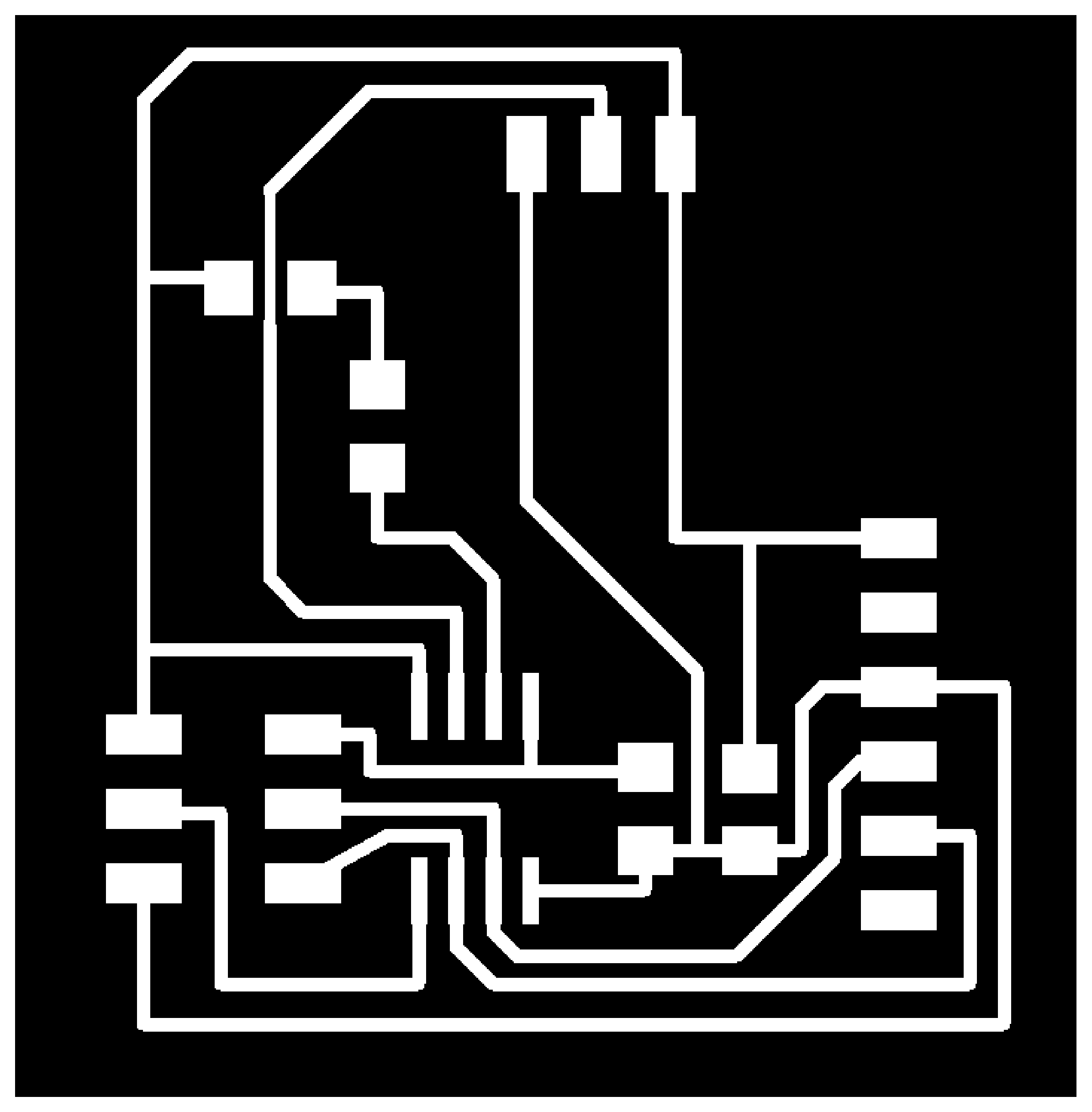
Working with Eagle


Traces miiling:
Interior Milling
List of Parts:

Note:
I used Orange lED insted the Green. Also, I forgot to mention adding 3*1 Hidder Pins to conncet the Pir pins with it.
While Soldering:

Hero Shoot !

Attiny 45 arduino Pins:

Hero Shoot!
Blink Test :
Hero Shoot! PIR Motion Sensor With Arduino
PIR Motion Sensor Arduino Code:
/*
PIR HCSR501
modified on 5 Feb 2019
by Saeed Hosseini @ ElectroPeak
https://electropeak.com/learn/guides/
*/
int ledPin = 3;                // LED
int pirPin = 4;                 // PIR Out pin
int pirStat = 0;                   // PIR status
void setup() {
 pinMode(ledPin,OUTPUT);
 pinMode(pirPin, INPUT);

}
void loop(){
 pirStat = digitalRead(pirPin);
 if (pirStat == HIGH) {            // if motion detected
   digitalWrite(ledPin, HIGH);  // turn LED ON
 delay(10);
 }
 else {
   digitalWrite(ledPin, LOW); // turn LED OFF if we have no motion
 }
}