12. Output devices
Group assignment:
Measure the power consumption of an output device.
Individual assignment:
Add an output device to a microcontroller board you’ve designed, and program it to do something.
–
SUMMARY
Have you?
-
Described your design and fabrication process using words/images/screenshots or linked to previous examples > DONE
-
Explained the programming processes you used and how the microcontroller datasheet helped you > DONE
-
Explained problems and how you fixed them > DONE
-
Included original design files and code > DONE
ASSIGNMENT
Individual - Speaker to play sound
How it works (physical principle)

When using a speaker, audio is converted from electrical ‘pulses’ to pressure waves that the speaker produces on the air with its movement. In this case, the source (speaker) is moved by voltage and magnetic field variation which creates sound waves with the same frequency than the audio one.

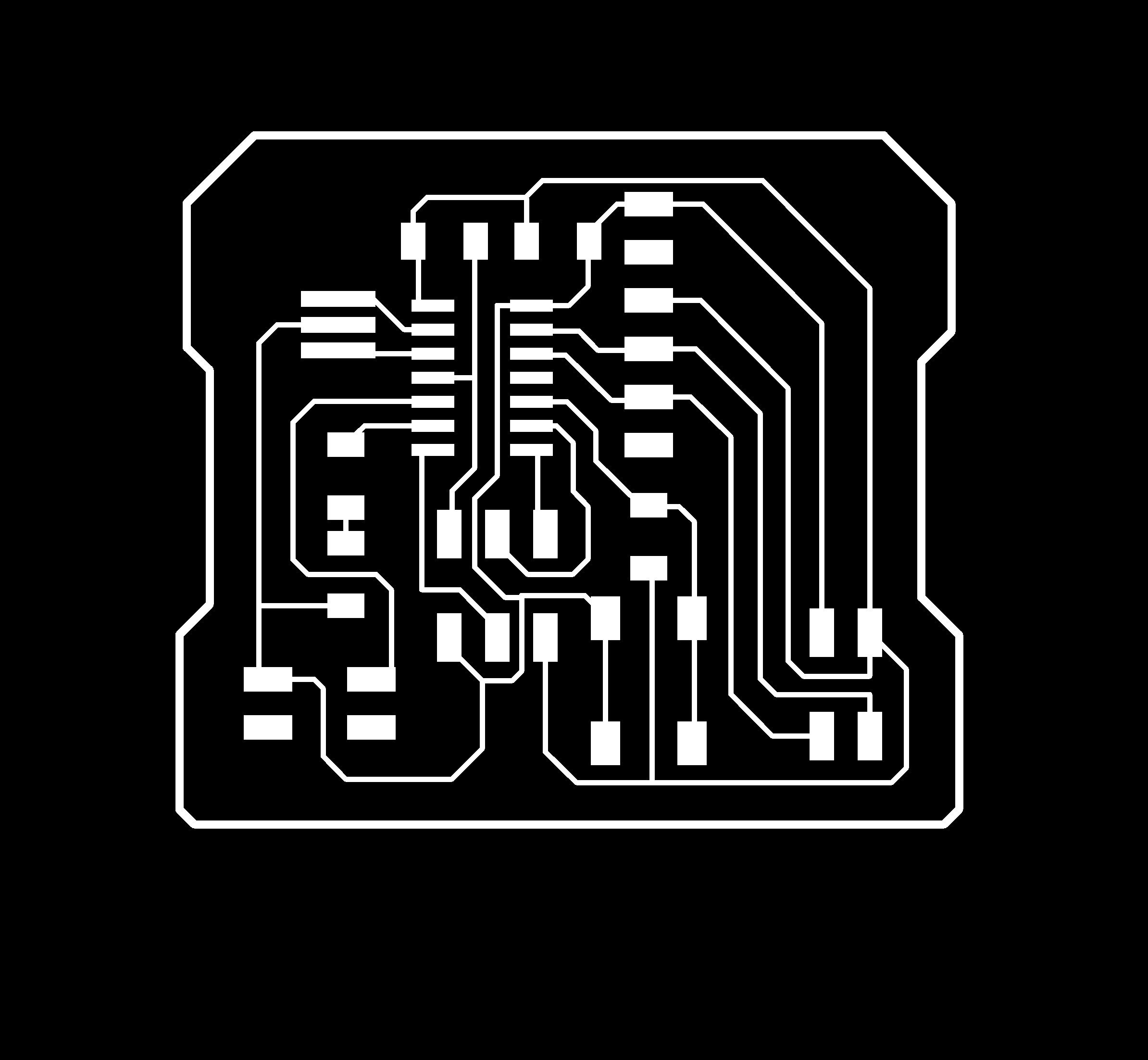
Circuit design:
For this assignment I decided to use the ATtiny44 micro-controller according to these reasons:
Firstly, I wanted to design a board with a simple speaker that could play a sound when a button on the board would be pressed. In this case, the PSR-23F08S-JQ speaker would work fine, because it doesn’t need any additional power supply over de +5V from the FTDI (computer USB port). I thought that the speaker (pin_,GND) must be connected to a PWM pin to manage the voltage variations.
Secondly, I considered the idea of using also another better speaker that would need an additional power supply. For that, it would be necessary to consider the use of another ATtiny44 pins to add 2x2 power and 2x2 speaker headers, with the support of a MOSFET and a REGULATOR, apart from devices to manage the resistance and the capacitance. In any case, it would be interesting to have both speaker systems on the same board to check the result difference from one to the other.
Thirdly, I wanted to add the same 2x2 header than in input devices to allow communications between boards.
I also considered very important to put the speakers into acoustic boxes to enhances the sound (specially on low frequencies) loudness.
Finally, this speaker-board also has a state LED that also can work as an output. To make it more interesting, the LED works on the pin 5 of the ATTiny44. According to the microcontroller datasheet, this pin works as PWM, as desired to make effects on the light output.


Board production
I used the Roland SRM-20 to trace and cut my board with 1/64’‘ and 1/32’‘ mills. The .rml files were generated from fabmodules.org:

Speaker Code
int speakerPin = 9;

int length = 15; // the number of notes
char notes[] = "ccggaagffeeddc "; // a space represents a rest
int beats[] = { 1, 1, 1, 1, 1, 1, 2, 1, 1, 1, 1, 1, 1, 2, 4 };
int tempo = 300;

void playTone(int tone, int duration) {
for (long i = 0; i < duration * 1000L; i += tone * 2) {
digitalWrite(speakerPin, HIGH);
delayMicroseconds(tone);
digitalWrite(speakerPin, LOW);
delayMicroseconds(tone);
}
}

void playNote(char note, int duration) {
char names[] = { 'c', 'd', 'e', 'f', 'g', 'a', 'b', 'C' };
int tones[] = { 1915, 1700, 1519, 1432, 1275, 1136, 1014, 956 };

// play the tone corresponding to the note name
for (int i = 0; i < 8; i++) {
if (names[i] == note) {
playTone(tones[i], duration);
}
}
}

void setup() {
pinMode(speakerPin, OUTPUT);
}

void loop() {
for (int i = 0; i < length; i++) {
if (notes[i] == ' ') {
delay(beats[i] * tempo); // rest
} else {
playNote(notes[i], beats[i] * tempo);
}

// pause between notes
delay(tempo / 2);
}
}
Speaker Test:
Vibration motor test:
Group assignment:
This week, as a group assignment, examine the power consumption of the circuit.
Research¶ The power consumption is obtained by the following formula. W = V × A
If power consumption is multiplied by time, it will become power consumption every hour. Wh = W × h
An example of power consumption in Japan. In Japan, the basic rate changes depending on the number of amps to be contracted.
| Amps | BasicRate |
|---|---|
| 10A | ¥280.80 |
| 15A | ¥421.20 |
| 20A | ¥561.60 |
| 30A | ¥842.40 |
| 40A | ¥1,123.20 |
| 50A | ¥1,404.00 |
| 60A | ¥1,684.80 |
And the rate of wattage per hour is changed in three steps
| kWh | Rate |
|---|---|
| 0 - | 120 ¥19.52 |
| 120 - | 300 ¥26.00 |
| 300- | ¥30.02 |
Useful links
Instruments Output device
- Peltier Element
- Spec
- 12V
- 5A
- Internal resistance
- 2.4〜2.7Ω
- 12V / 2.5Ω = 4.8A ≠ 5A
- Measuring tools
- DC Power supply
- Non-contact Thermometer
Check the power consumption by increasing 2V from 1V
- 3V → 0.75A

- 5V → 0.98A

By measuring the temperature, I was thinking about examining the relationship between power consumption and temperature. However, when the measurement took time, the temperature rose during that time. As a result, at 7 V, the Peltier element was destroyed and no current flowed.
Power consumption of Peltier device (TEC-12705)
Power consumption and charge for 1 hour at each voltage
| Voltage | Ampere | Killo Watt per Hour | Charge |
|---|---|---|---|
| 1V | 0.27A | 0.00027kWh | ¥0.00527 |
| 3V | 0.75A | 0.00225kWh | ¥0.0585 |
| 5V | 0.98A | 0.0049kWh | ¥0.095648 |
| 7V | 1.40A | 0.0098kWh | ¥0.191296 |