5.Electronics production|Week 4
Assignments:
group assignment:
characterize the design rules for your PCB production process
individual assignment:
make an in-circuit programmer by milling and stuffing the PCB,test it, then optionally try other PCB processes.
File Download
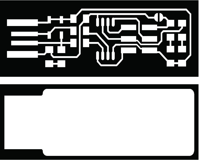
Trace width test “traces” png file
Trace width test “traces” rml file
Trace width test “interiors” png file
Trace width test “interiors” rml file
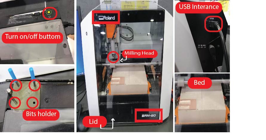
Machine:
Size: 451.0 (W) x 426.6 (D) x 426.2 (H) mm
Max cutting area: 232.2 (X) x 156.6 (Y) mm
Power: Machine: DC24V, 2.5A,
Dedicated AC adapter: AC 100-240V ±10%, 50/60Hz
Included items: USB cable, AC adapter, Power cord, Cutting tool, Collet, Set screw, Spanners (7,10mm / 0.28, 0.39 inches), Hexagonal wrench (size 2,3 mm / 0.059, 0.12 inches), Positioning pins, Double-sided tape, Start-up page guidance card
Software :
• Before using the Roland SRM-20 MonoFab you have to keep those safety rules in mind:
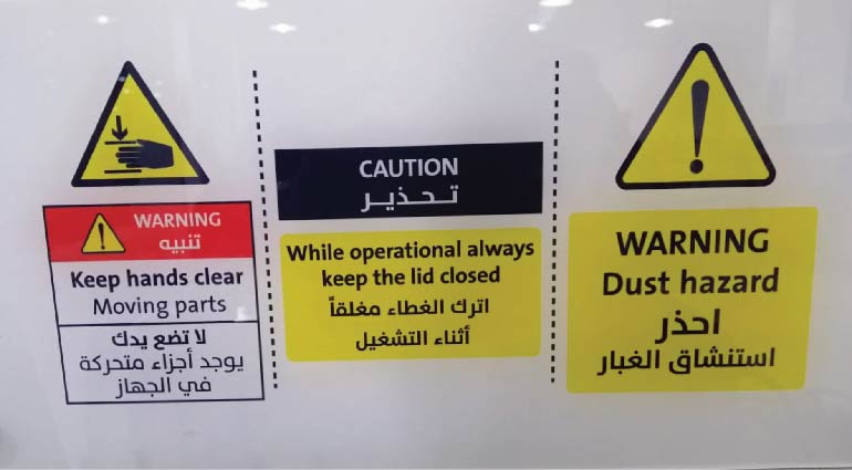
• Dust hazard.
• Keep hands clear from moving parts.
• While operation always keep the lid closed.
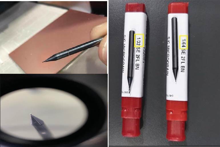
Tools used:
• Milling Bits: We used two milling bits; for traces 1/64” (0.4 mm), and for interiors 1/32” bit (0.8 mm).
Milling Machine Bed:
The gif above shown that you can Unscrew the base by moving the four fixed screws to make it easier for you to work freely outside the machine to be in safety.
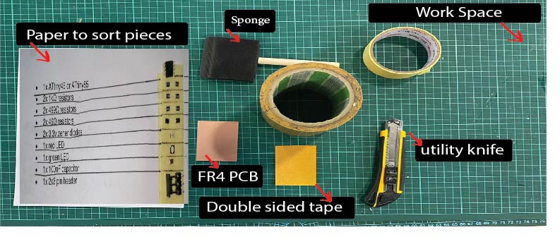
FR4 PCB Double sided tape:
FR4 PCB: FR4 is code name for glass-reinforced epoxy laminated sheets. Due to its strength, as well as its ability to withstand moisture and fire, FR4 is one of the most popular PCB materials.
Double sided tape: To fixate the PCB on the bed of the milling machine.
Tools you will use it in this assignment:
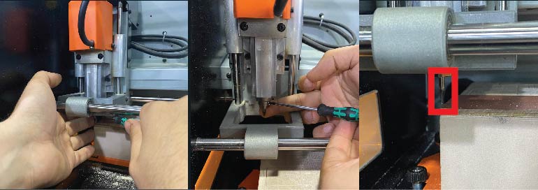
The process of inserting the blade is carefully placing it with two fingers under and then tighten it and for extra caution we placed a sponge on the bed :
• Now we are ready to cut but first we have to put the right settings, where the option “Machine coordinate system” is to move the blade and the option “User coordinate system” is for getting the machine to cut :
Files to download
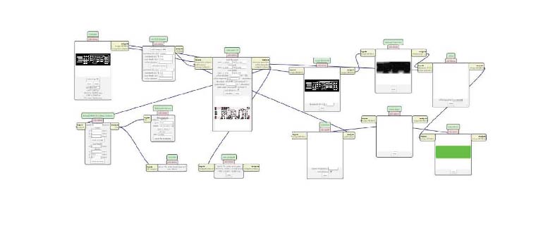
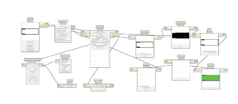
mods
Mods is a project lead by Prof. Neil Gershenfeld in the CBA that allows one connect modules, i.e. devices that do very specific tasks, using a friendly web interface. It allows people to use a web-browser to connect devices and do computation. By doing so it can be used to build modular machines that do a variety of tasks.
The individual assignment :
For the individual assignment we have to make an in-circuit programmer by milling and stuffing the PCB, test it, then optionally try other PCB processes.
Step one: Getting the files.
From the Fab Academy 2020 Schedule we go to Electronics Production and download two PNG files; under CAM, to get familiar to the design rules for your PCB production process.
Step two: Convert PNG files to code that the machine can read.¶ PREPARING MODS:¶ We go to Mods, then choose the next commands:
Preparing the file on mods: Watch this Gif!
I made a “Gif” for the full process in Mod hope it useful to you!
for more details watch this video from FabAcademy
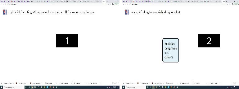
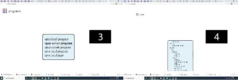
Right click on the mods interface to open the selection list. Click on programs > open server program > machines > Roland > mill > SRM - 20 > PCB PNG .
Click on “mill trace (1/64)” to select the right milling bit. The copper base thickness of the FR4 PCB is 0.1 mm. “Cut depth” is set to 0.004” (0.1 mm). “Offset number” controls the milling spacing around traces. “Offset number” is set to 0, which means the spacing, where applicable, will be the maximum to have a clean cut (unwanted copper will be removed); 4 x 1/64” (0.4 mm) = 1/16” (1.6 mm).
After preparations of files above, it’s time to cut your work …
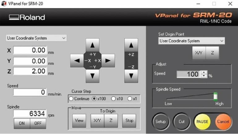
1-Opened the “VPanel software” and selected “Machine Coordinate System” option from the dropdown menu. Used the “+X, -X” and “+Y, -Y” arrows to move the head over the bottom left corner of the PCB. Used the “+Z” arrow to have enough space between the spindle and the PCB to insert the milling bit.
2- Inserted the 1/64” milling bit in the spindle collet leaving about 25% of its length outside. Tie the fixing screw.
3- Using the “-Z” arrow, moved the spindle down till there is about 5 mm between the PCB and milling bit tip. Held the milling bit between your fingers and untie the fixing screw then the milling bit down till it touches the PCB. Tied screw firmly. This is my start position.
4- From the “Set Origin Point” dropdown menu to the right, made sure to select “User Coordinate System”. Clicked on “XY” and “Z”. This will define the current position as the home or zero position in the user coordinate system. Selected “User Coordinate System” from the dropdown menu to the left. The values of “X”, “Y”, “Z” should be zeros …but before started the machine I moved the z axis 2 mm up to give it space the spindle to turn around when the machine is on with no damage.
• Here we click on cut and then a window pops out showing the jobs that has been added recently so we delete them and added our job which is the linetest trace and outline.
Also, I recorded the full of process that I did it: Watch this Gif!
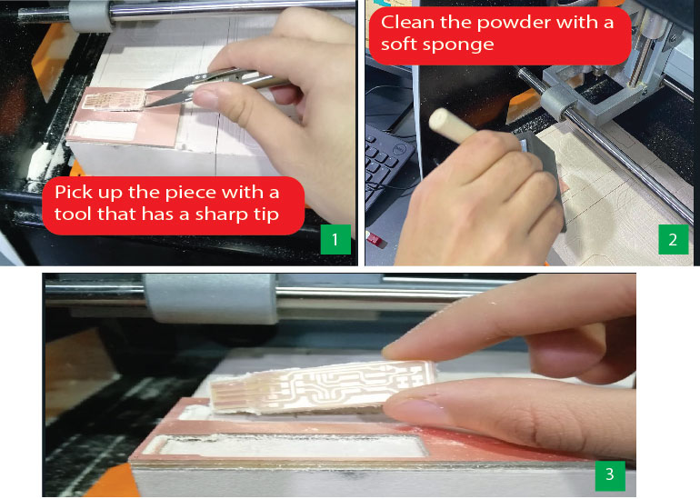
While Milling:
After Milling:
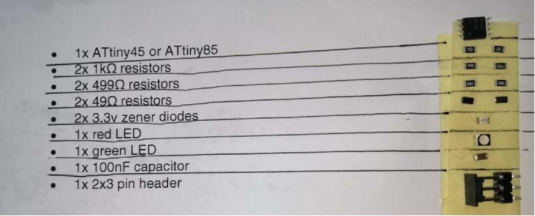
The required components
Then I have prepared the components :
| Components needed | Quantity |
|---|---|
| ATtiny45 or ATtiny85 | x1 |
| 1kΩ resistors | x2 |
| 499Ω resistors | x2 |
| 49Ω resistors | x2 |
| 3.3v Zener diodes | x2 |
| red LED | x1 |
| Green LED | x1 |
| 100nF capacitor | x1 |
| 2x3 pin header | x1 |
 |
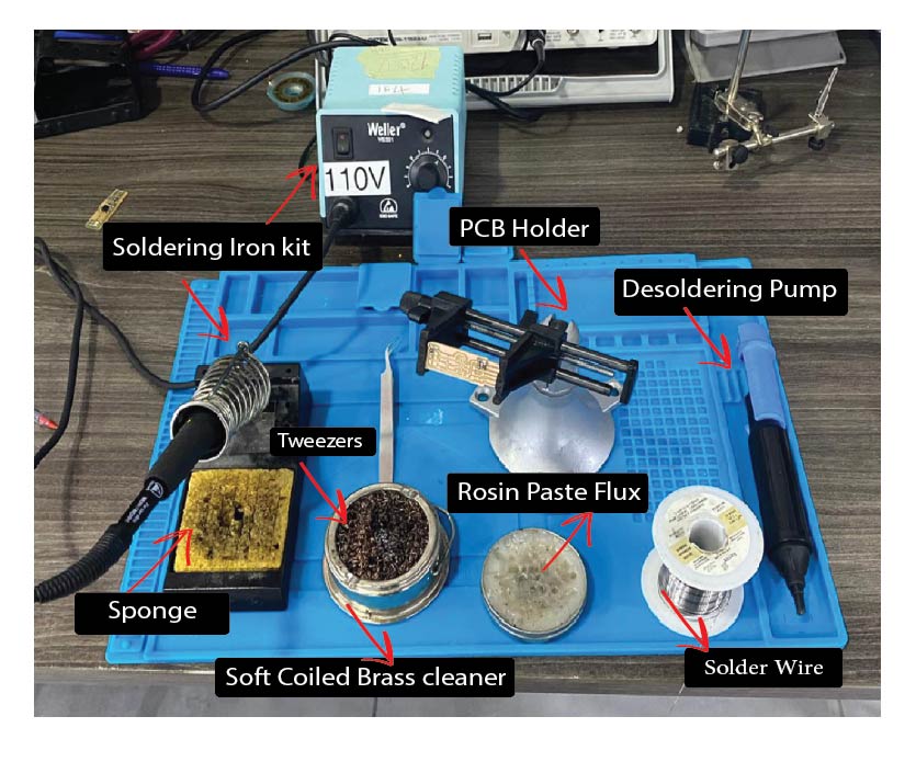
Tools you will use it while soldering
Solder the parts to the PCB:
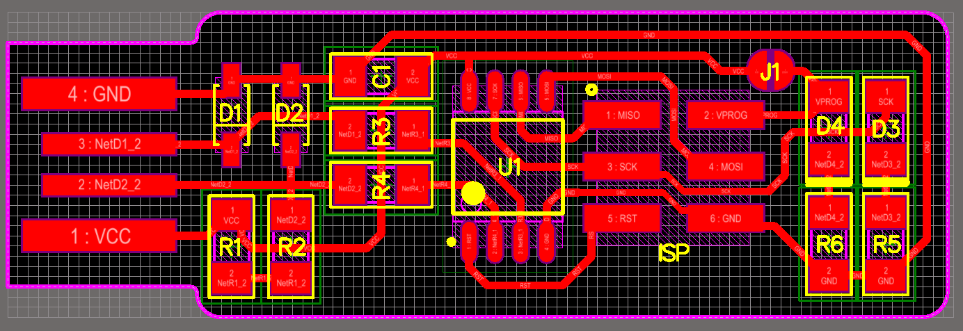
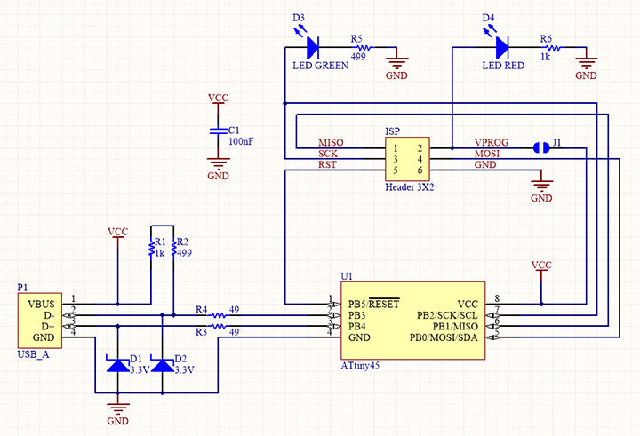
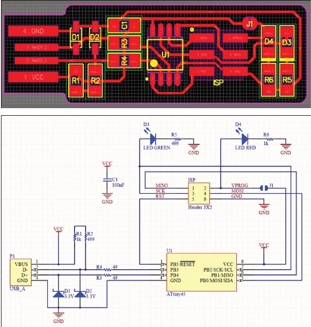
According to the schematic and board image from the links below as a reference for component values and placement. Thank you Brian For the great tutorial it was really helpful
Hero Shoot of Soldering ATtiny45 :
InShot_20210223_013115952 from Ammar Alkhatib on Vimeo.
Hero shot !
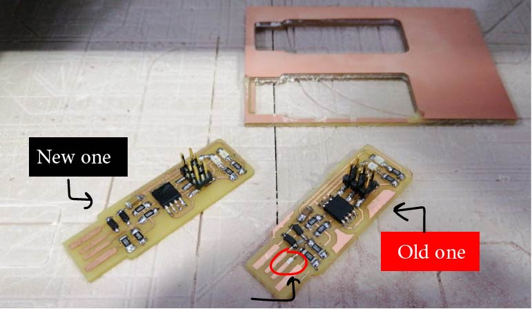
While soldering I made a mistake by connect Pin 2&3 together (I didn’t notice that) that cause damaged the “Diode” so I remake a new one to check my work is without any problems.
Group assignment
For the Group assignment we have to learn about the - ROLAND SRM-20 and how it works, in order to cut and mill the default board then solder the components to be used as a ISP !
Step 1 : We downloded the png test files: traces
Step 2 : open Mods then follow the steps as shown in the pic to import the png file to get the rml file in order to start the mill processes.
• We used Milling bit 0,8 (1/32”) for the Interior. • Milling bit 0,4 mm (1/64”) for the traces.
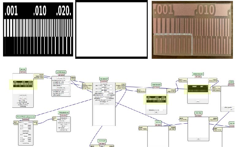
The image above shown the board that we made it cut in half that happened because of we try to reduce the cost.
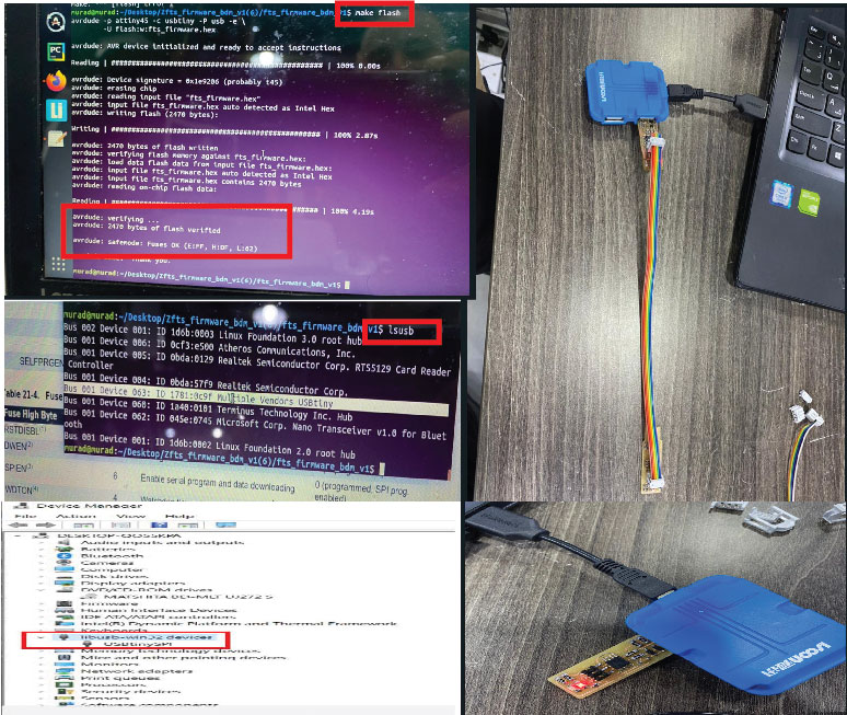
programming The board
to program the ISP you have to connect it with a programmed ISP:
Step 1: Enter the command “make flash” then if it works
Step 2 : Enter the command “make fuse” after that to make sure your ISP is actually programmed
Step 3 : enter the command “lsusb” and tha will list USB devices. lsusb ///The lsusb command in Linux is used to display the information about USB buses and the devices connected to them.
If you see a “Multiple Vendors USBtiny” device that means it worked.