7. Electronics design|Week 6
INDIVIDUAL ASSIGNMENT
Redraw an echo hello-world board, add (at least) a button and LED (with current-limiting resistor) check the design rules, make it, and test it extra credit: simulate its operation
For the board design (echo hello-world board) I have used “Eagle fusion 360” software

Redrawing the Echo Hello-World board:
Files to download:
Starting with Eagle!
Warning:
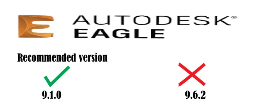
I have started this week by downloading Eagle software from Autodesk for the first time it is a PCB designing tool. New knowledge for this week. First I download Eagle, and activated. What I mostly like about Eagle the graphics, it is easy-to-use tools, and vibrant community there are many YouTube tutorials explain everything step by step. I followed one tutorial to know more about routing, add parts, how to label and many other things. I started with a basic circuit to practice before starting with the assignment.
To do this, the first thing I have to do is download the Fab Libraries and make them available in Eagle.

To activate the electronic library, from Eagle you have to right-click and import them, accessing “Open library manager”.
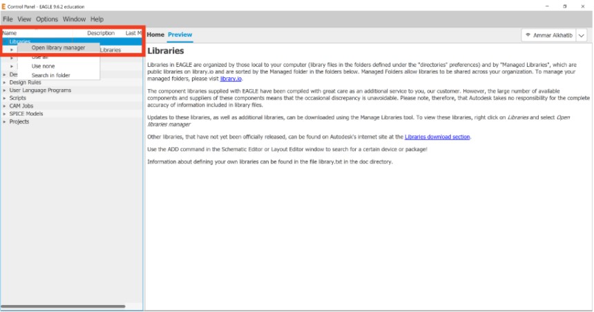
From here the Eagle libraries are imported from the Fabacademy link.
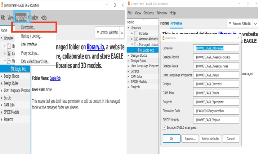
From “Options” I can see the directories where the Eagle libraries and the design rules are , here I am going to find the library that I need.
- Then right click on the project which is named “echo hello world” based on the assignment then choose schematic in order to get the components for the board.
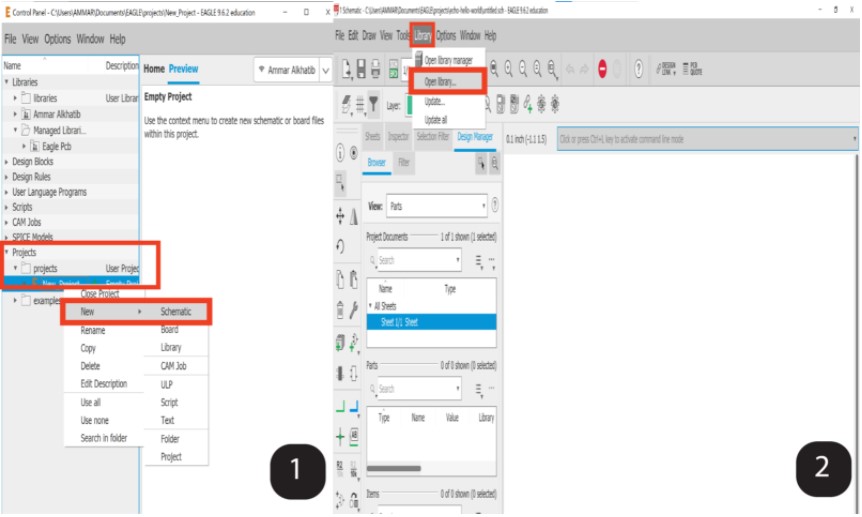
-
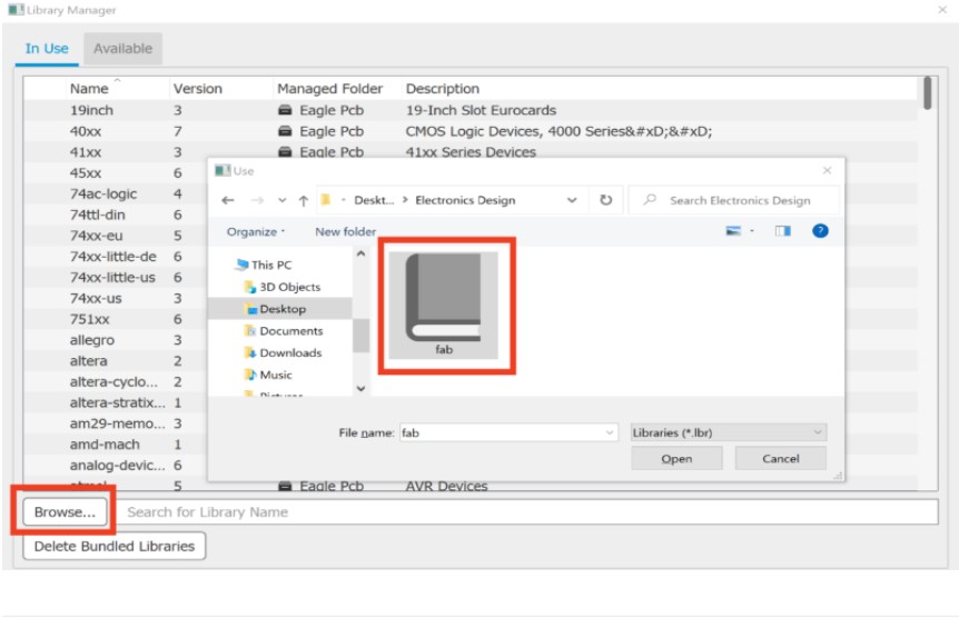
then from the upper panel choose “library” – ” open library ” too add the assignment components from “Eagle fab library”.
-
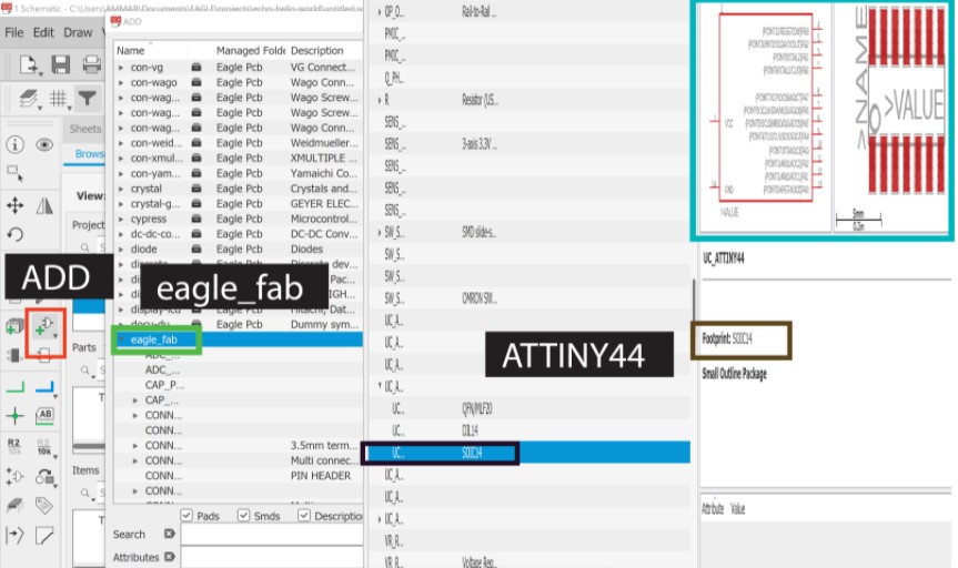
In this point the library is ready to be used in the schematic click from the side panel on “Add part” choose “Eaglefab” from the drop menu to get the components appered.

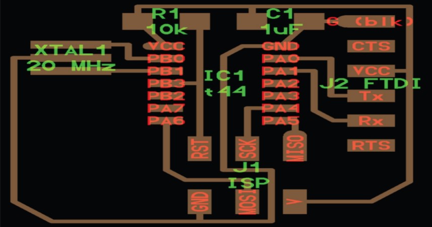
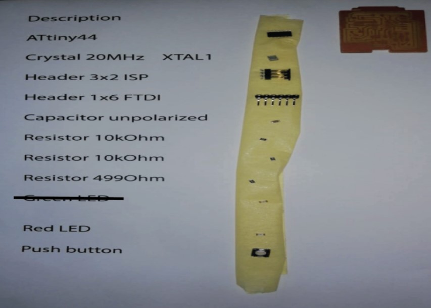
Components
These are the components that I need to make the “Echo Hello Board”.
| Components | Information |
|---|---|
| 6-pin programming header | For programming the board. |
| Mmicrocontroller:attiny44A | Once the microcontroller is programmed, the program stored in non-volatile memory. This means that it will remember the program. |
| FTDI header | Powers the board and allows board to talk to computer. |
| 20MHz resonator | External clock. The attiny has a 8Mhz clock but the resonator is faster (increase the clock speed of the processor) and more accurate. |
| Minimum components you should add | Information |
|---|---|
| Resistor (value 10k ohms) | Pull-up resistor. |
| LED(Light Emitting Diode) | (LEDs have polarity - the side with the line is the cathode and connects to the ground side). |
| Resistor (value 499 ohms) | Purpose: current limiting resistor. (Why do we need a current limiting resistor? So we don’t burn out the LED). |
| Resistor (value 10k ohms) | Because, the LEDs we are using are rated for the typical forward voltage is between 1.2-2.2V, so, we need to use a 82 ohm resistor or above to avoid blowing out the LED. I chose to use a 10k ohm resistor, but you could use other value. |
| • Button. | — |
| • Ground. | — |
| • VCC. | — |
| Connector pin 10 (PA3) on the micro-controller to the button. | — |
Ohm’s law:

for choosing (499 ohms resistor) to protect the red led which is have a 1.8v so depend on the law [V= I*R] = [1.8/499=I] = 227 mA , also I read in the datasheet of the red led the best resistor choices be around 333 ohm - 1k ohm.
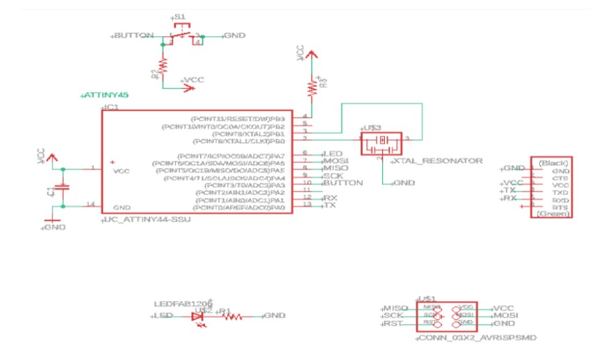
Design
From Eagle, in the schematic window, I look for the fab library and there its components:
First I find and insert the ATtiny44 microcontroller.
After this you choose the needed components for the board for example I picked “ATTINY 44-SSU”.
Then the component will be added to the schematic plan in order to link it with the other components.

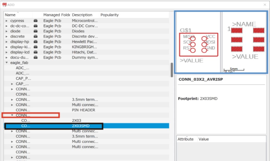
Then the 6 pin connector (AVRISP)
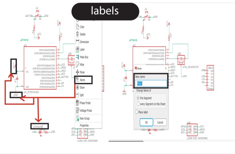
After introducing all the components, I introduce the connection cables, and in other cases I put labels that will serve to connect some terminals (pins) with others.
Notes:
Cables

Labels
Now comes the complicated, at least for me …
I go to the window “Board” (I leave the Schematic) of the Eagle program.

Autrouter:
Autorouting will automatically route the wires for you, but it is not very efficient, or there may be a glitch somewhere. It is best to design the board while using it as a reference only.

The tutorial that I have followed and to which I have previously referred, indicating its access link, contains indications about the design rules that I have not yet followed, specifically these types of things were indicated:
Design rules check
After designing our board we need to check that the endmill we are using is able to go between all the traces so the machine is able to cut successfully the board. For that we are going to use Design Rules Check (script) that will check that there is enough space everywhere.
To do this, you can follow these steps:
• Download the DRC script from here
• Type in EagleCad drc and press enter.
• A new dialog box should appear where you can LOAD the script.
• If everything is correct no error messages should appear.
• In case some red areas appear between the traces, you should move the traces leaving more space between them.
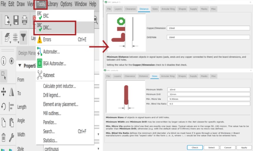
I have to load the design rules for it, I have to access DRC and Load. I select fab.dru(defaul) and then “Open”
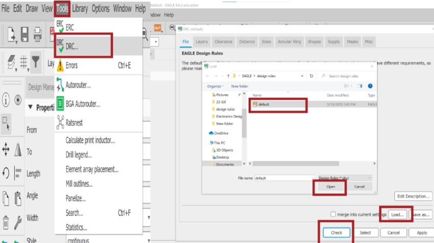
And then you have to do a “check” to see if I have complied with the design rules.
Click on Design Rule Check “DRC” and then “Check” to see if there are any errors or warnings in your board.
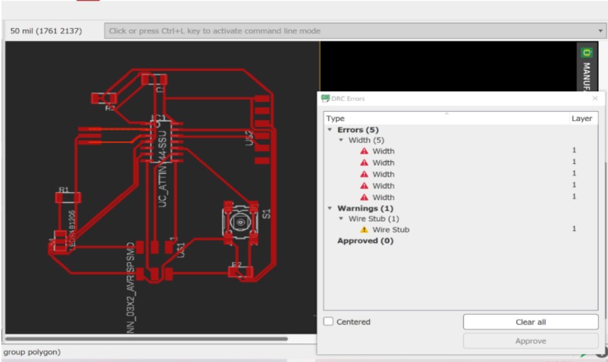
I get more than many errors, and most have to do with the thickness of the circuit lines that I set by default, are too thin.
Now I have to change thicknesses and I don’t know if there is a way to change them all at once or I have to go one by one …
These are the rules that I have to follow and it.
I did this because it has not given us errors of this type.
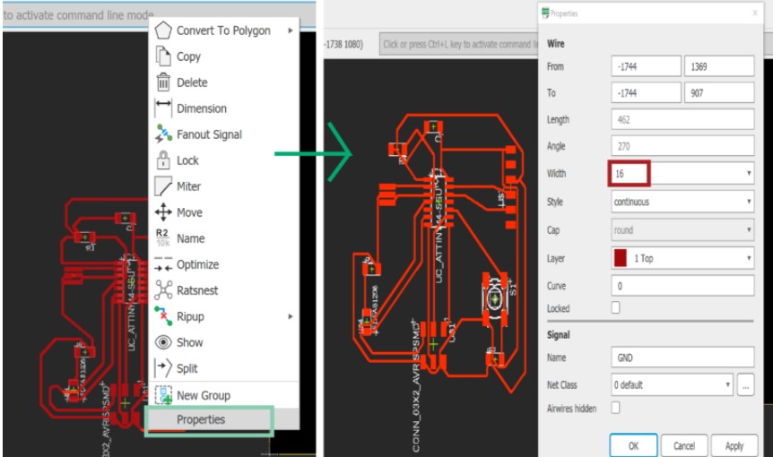
So I proceed to change the track width of my already configured board layout one by one.
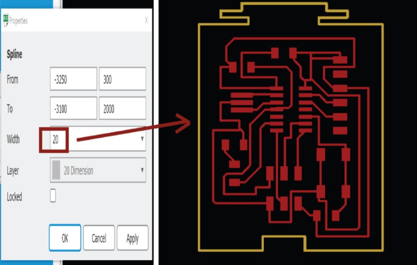
Change from 6 which is by default to 16. In “properties” that appear by right-clicking on each track.
This is my board with all tracks changed to 16mm.
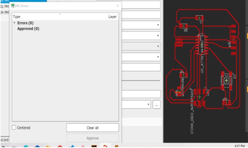
I finally solve all the errors. !!
Now we will draw a cutting lines around the board. Click on “Line” and then select layer “20 Dimension”. The cut lines will part of this layer. You can use straight lines and arcs.
Now we will draw a cutting lines around the board ( I draw a Batman Symbol in this shape I used lines). Right Click on the yellow “Line” and then select layer “20 Dimension”. The cut lines will part of this layer.
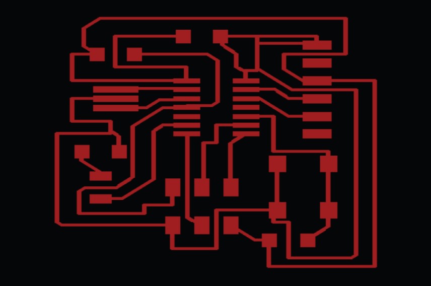
I save as .png image (default format) in the folder of my choice.
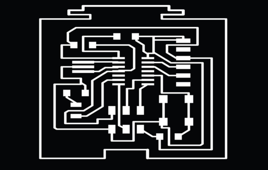
Zoom you board to fit window. Go to “File > Export > Image”. Give your file a name, check “Monochrome”, set resolution to “1000 dpi” and set “Area” to “Window”. Click “OK”.
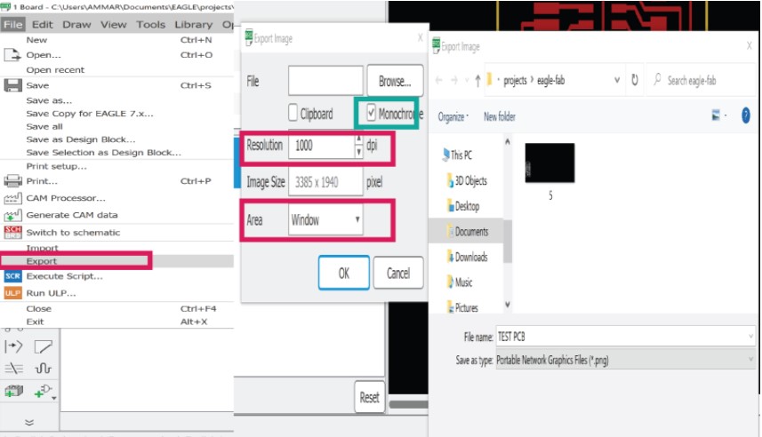
The exported image shown below.
MOD-Traces

MOD-Interiors
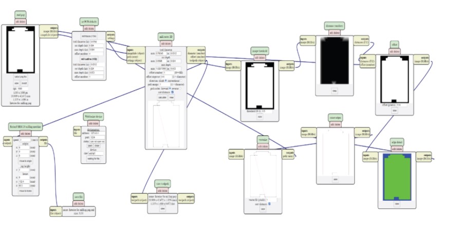
Preparing for milling:
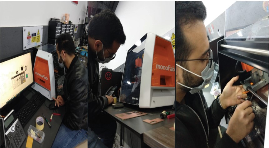
While Traces milling :
While Interiors milling :
Electronics Required:
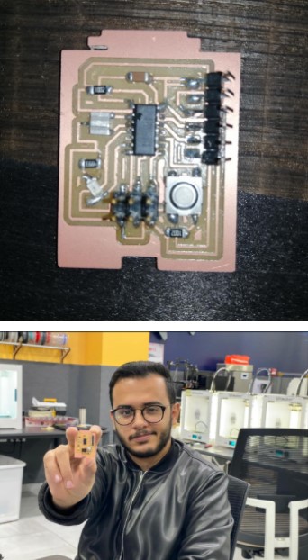
Hero shot!
Uploading the Code:
I uploaded the code using Arduino software after downloading few libraries for the windows check the embedded programming for more details … so after the computer recognized the ISP of the PCP I connected the ISP PCP to the ISP of my board then on Arduino software I recognized its appearing and was able to transfer the code
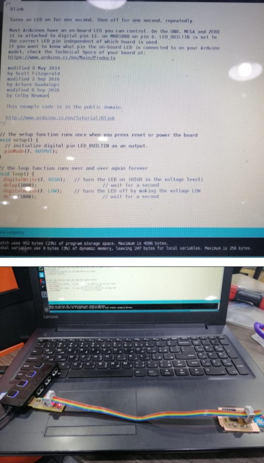
Ooops!
I had problem with my led path because of that I bring a Led and connect it manually to improve that it’s work at all.
Blink Test
Group assignment
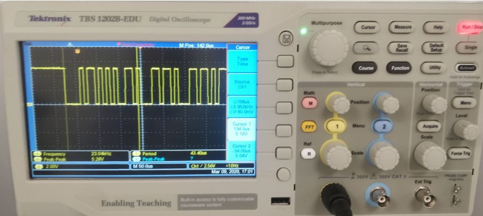
We started initially with the ATtiny connected with FTDI cable to the omputer, then we used the Oscilloscope probes to connect the board’s Ground and Rx pin . AFter that we interpreted the signals on the Oscilloscope’s screen using Ascii Table and made use of the rule of the UART protocol which ATtiny and the computer use. As shown in the picture the signal on the Oscilloscope represents character ‘A’ which is according to asccii 41 in hexadecimal or 01000001 but since the rules of the protocol state that there’s a start bit which is ‘0’ and then 8bit data sent with LSB first follows and ends with a logic ‘1’ stop bit. We used this and found out that the data matched the ‘A’ that was just typed.

Probes on the Ground and Rx
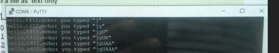
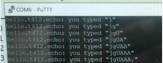
Sent character from the Computer
Next, we changed the probe from Rx pin to Tx pin to read the characters that were sent to the computer. As shown in the image the text sent by the ATtiny starts with hello and therefore ascii for ‘h’ (68 hexadecimal) shoulbe at the beginning according to the protocol it comes out as 00010110 and is confirmed to be matching the bit pattern on the oscilloscope. Next, interesting thing to measure is if the characters sent match the time duration on the oscilloscope as shown in the image the last characters are 31 in number and the duration for a single bit is 9 usec and according to the protocol one character is sent in a frame of 10 bits which makes it 109=90 usec duration for one character, therefore time required to send 31 characters would be 9031=2.79 msec which closely matches the value onthe oscilloscope.
Changing setup to read characters sent from ATtiny
Characters sent
Bit pattern of ‘h’ character from hello

characters duration.