9. Embedded programming
This week task as below:
- Individual project
Read the datasheet for the microcontroller you are programming
Program the board you have made to do something, with as many different programming languages and programming environments as possible.
Microcontroller datasheet
In order to know how to use a chip. We need to read the datasheet of the chip.
In this assignment, I will use Microchip ATTiny 44 as the chip for the board.
Step 1:
Downloading the datasheet from Microchip.
https://www.microchip.com/wwwproducts/en/ATtiny44
Step 2:
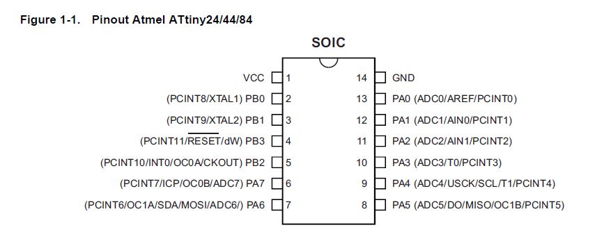
Understanding the pinout of ATmel Attiny 44
In the following diagram, you find that every pins have different name and function.
In this assignment,
Prepare for programming
I am going to use Arduino IDE to program my board.
Step 1:
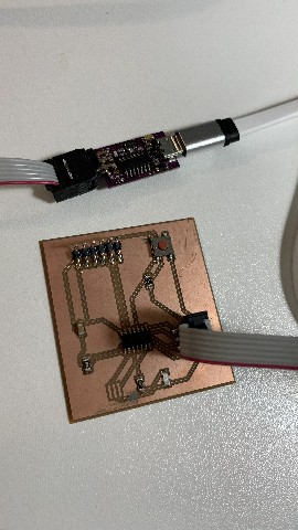
I have to connect a PCB together with my board so that it is ready for uploading the program into my board.
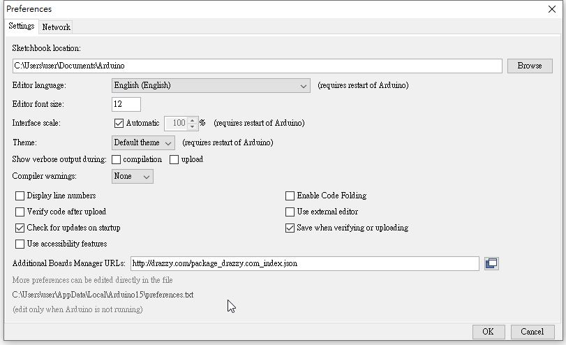
Step 2:
In Arduino IDE, I need to setup the additional boards manager URL.
I will use the following json file for ATTiny 44 which is my chip.
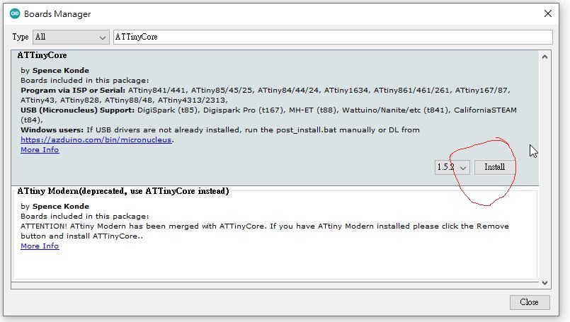
Step 3:
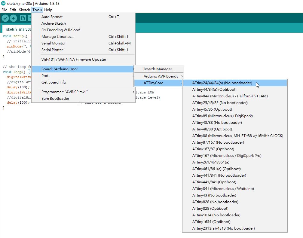
In the board manger, I am going to install ATTiny Core by Spence Konde.
It contain my board AT Tiny 44.
Step 4:
I have to choose my board : ATTinyCore \ AT tiny 44.
Step 5:
Also, I choose Chip : Attiny 44(a).
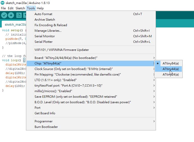
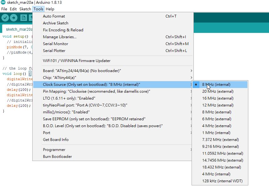
Step 6:
For the clock source, I choose 8MHz (internal)
Step 7:
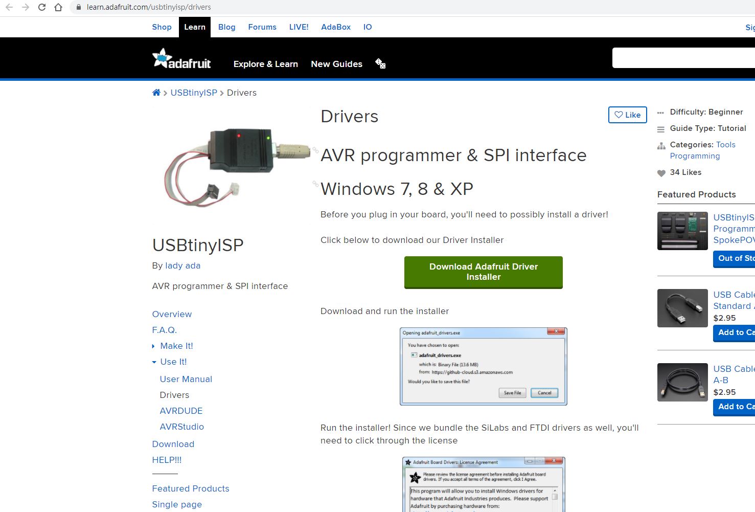
Also, I need to download a suitable driver for the AVR programmer & SPI interface.
Therefore, I download driver in the following webpage.
Step 8:
In the programmer, I have to setup USBtiny ISP (ATTinyCore)
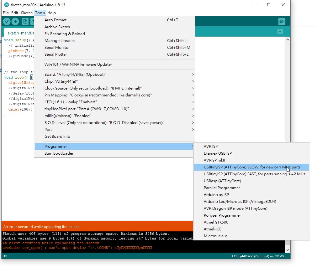
Step 9:
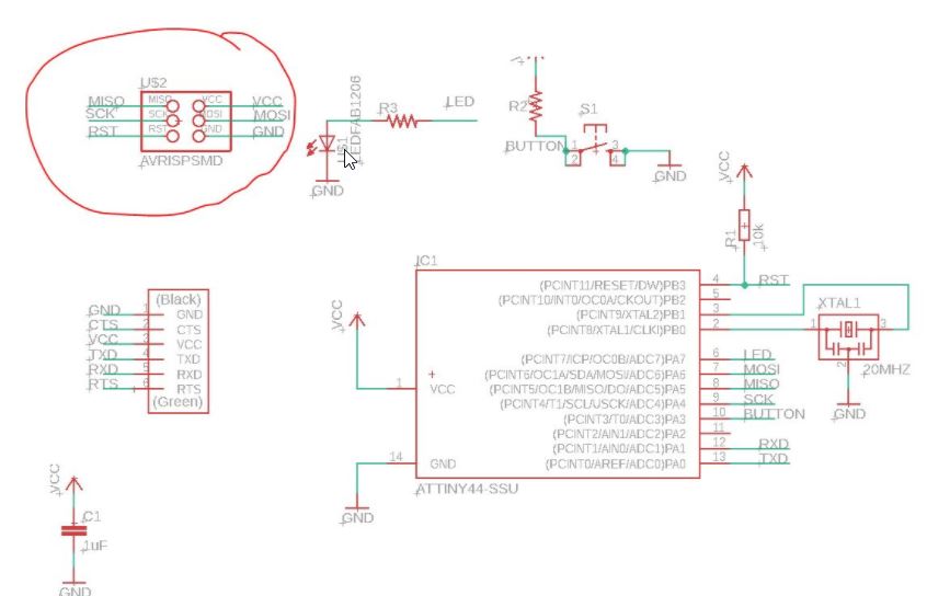
Here is the schematic of my board.
You are notified that PA3 is connect to the button. PA7 is connected to LED.
Programming Test 1
Step 1:
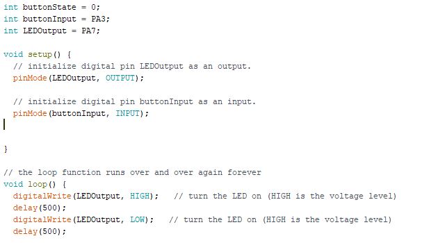
In the program, I have to setup three integer variable for easy understanding.
This is a hello program. The board only flashing for bright and dim regularly.
** Please be remind that the chip do not have crystal. Therefore the time is not accurate.
Step 2:
In the following video, you would view the testing.
Step 3:
The complete code is here.
int buttonState = 0;
int buttonInput = PA3;
int LEDOutput = PA7;
void setup() {
// initialize digital pin LEDOutput as an output.
pinMode(LEDOutput, OUTPUT);
// initialize digital pin buttonInput as an input.
pinMode(buttonInput, INPUT);
}
void loop() {
digitalWrite(LEDOutput, HIGH); // turn the LED on (HIGH is the voltage level)
delay(500);
digitalWrite(LEDOutput, LOW); // turn the LED on (HIGH is the voltage level)
delay(500);
}
Programming Test 2
Step 1:
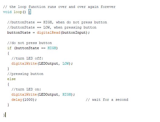
In the second program, I have to setup three integer variable for easy understanding.
This is a hello program version 2 . When someone press the button, LED will flash.
** Please be remind that the chip do not have crystal. Therefore the time is not accurate.
Step 2:
In the following video, you would view the testing.
Step 3:
The code in loop function is here.
// the loop function runs over and over again forever
void loop() {
//buttonState == HIGH, when do not press button
//buttonState == LOW, when pressing button
buttonState = digitalRead(buttonInput);
//do not press button
if (buttonState == HIGH)
{
//turn LED off:

digitalWrite(LEDOutput, LOW);
}
//pressing button
else
{
//turn LED on:

digitalWrite(LEDOutput, HIGH);

delay(1000);                       // wait for a second
}
}
You may also download the program here.
Please click here to download the ino file
Group assignments
Compare the performance and development workflows for different microcontroller families
Document your work (in a group or individually)
Here is the link of the group assignment .