8. Computer controlled machining
This week I worked on defining my final project idea and started to getting used to the documentation process.
This week task as below:
- Individual project
Make (design+mill+assemble) something big
To do list
-
Linked to the group assignment page
-
Documented how you designed your object (something big)
-
Documented how you made your CAM-toolpath
-
Documented how you made something BIG (setting up the machine, using fixings, testing joints, adjusting feeds and speeds, depth of cut etc.)
-
Described problems and how you fixed them
-
Included your design files and ‘hero shot’ photos of final object
Fusion 360 to create a 3D model
This is my second time to use Fusion 360 to create some 3D design.
I am going to make a rectangle box for containing somethings.
Step 1:
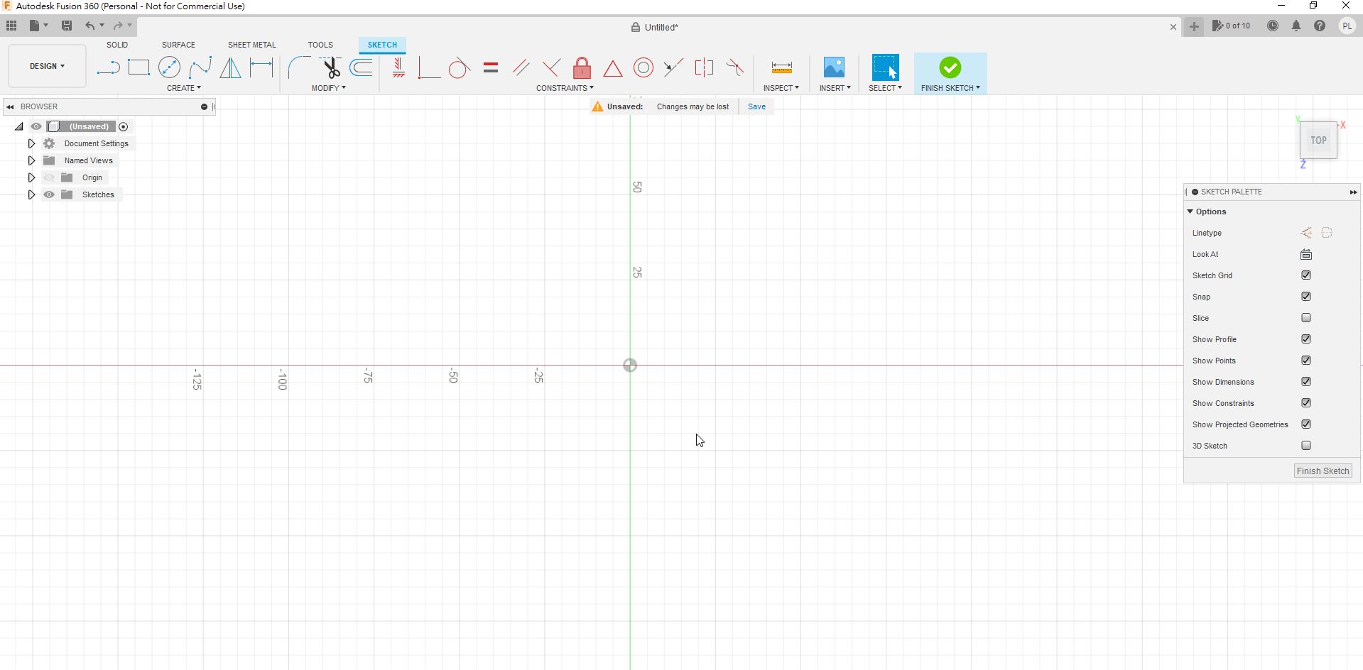
Firstly, I need to create a new sketch.
Step 2:
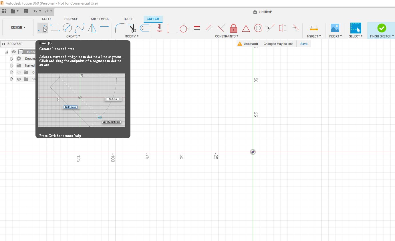
Next, I will use Lines feature to draws the line of the box.
Step 3:
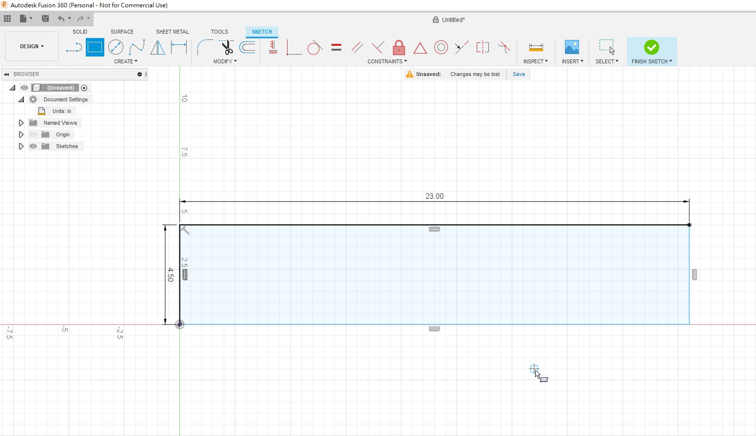
Then, I draw a rectangle as below.
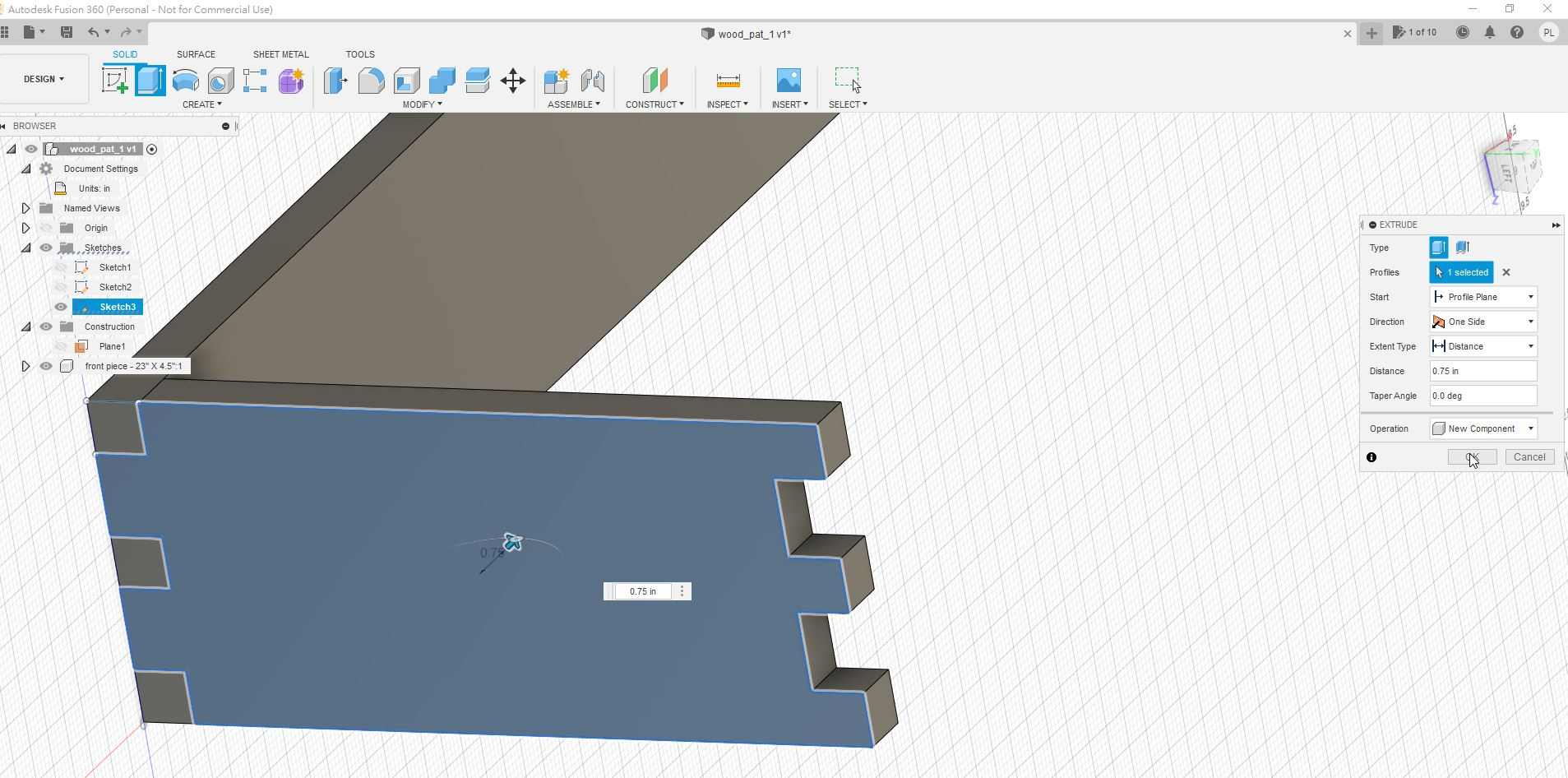
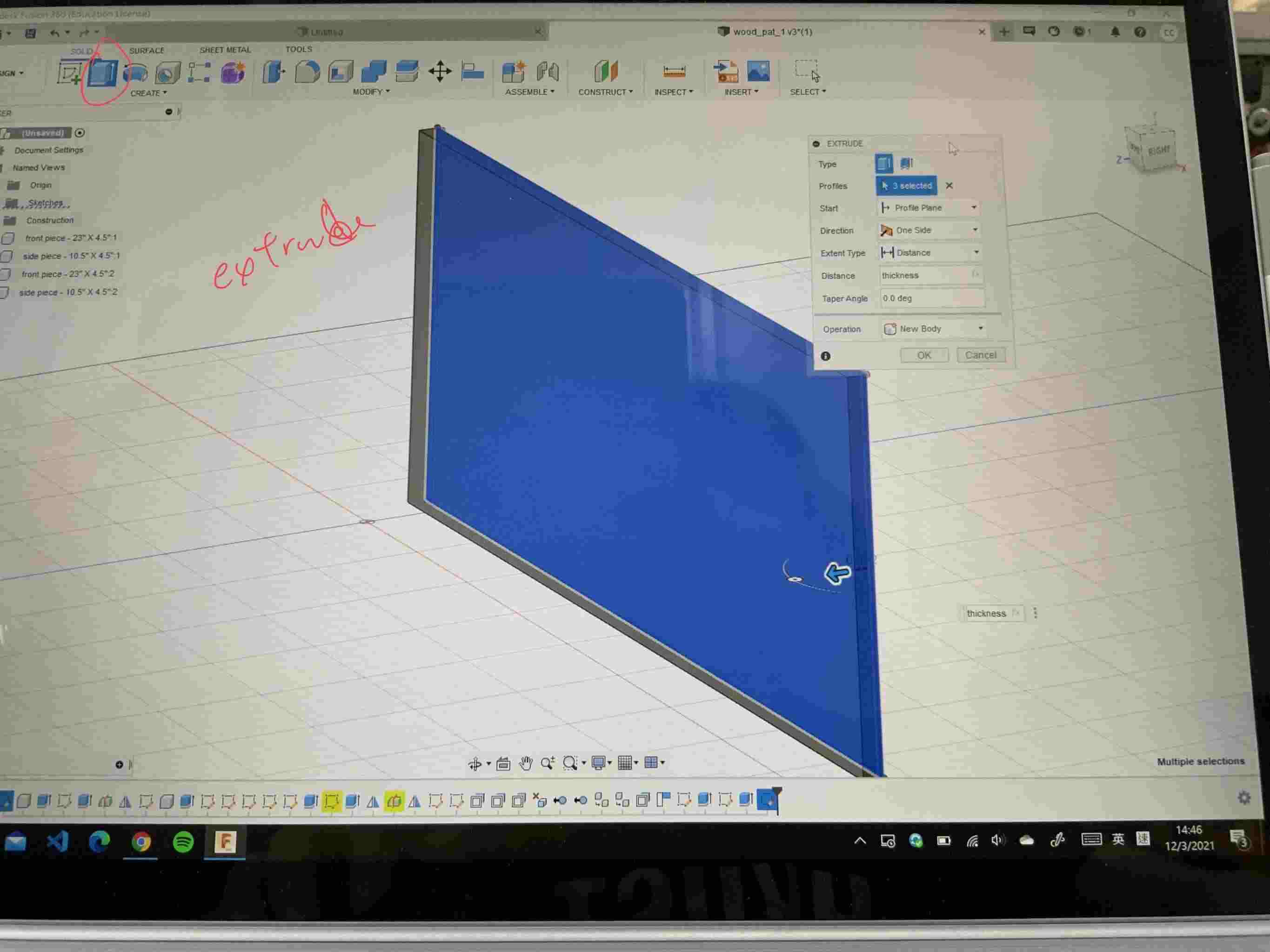
Step 4:
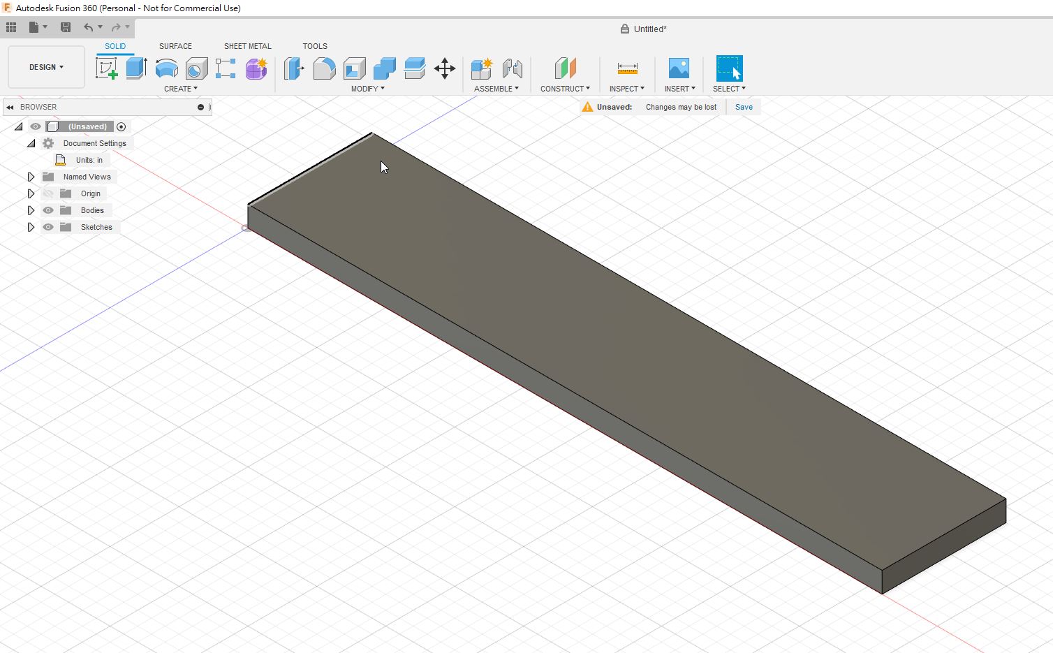
By using extrude, extend the rectangle to be a solid box.
Step 5:
I have to draw the joints like this for joining different planes later.
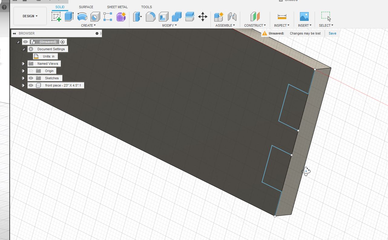
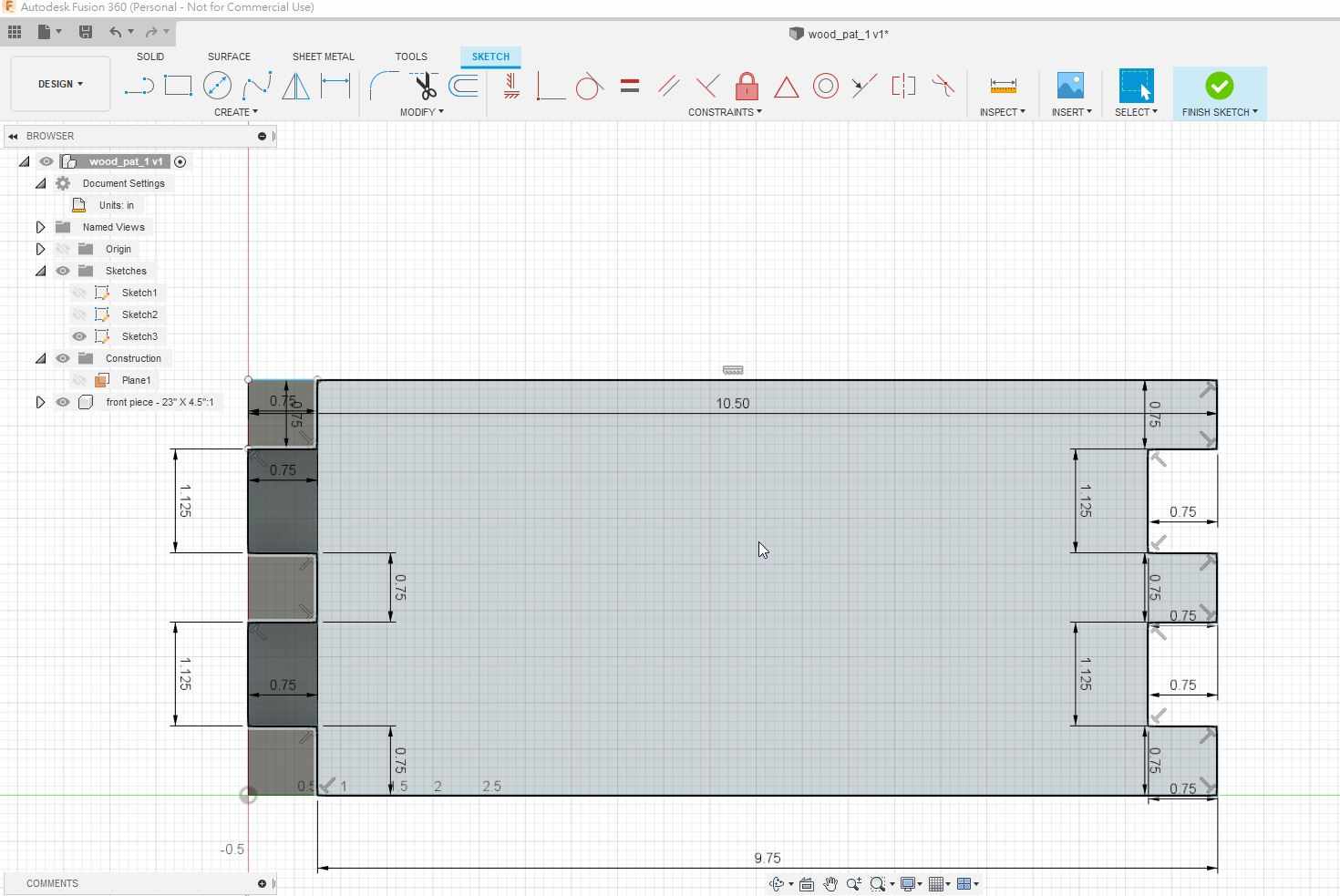
Step 6:
You may read that the length for the joints in details as below.
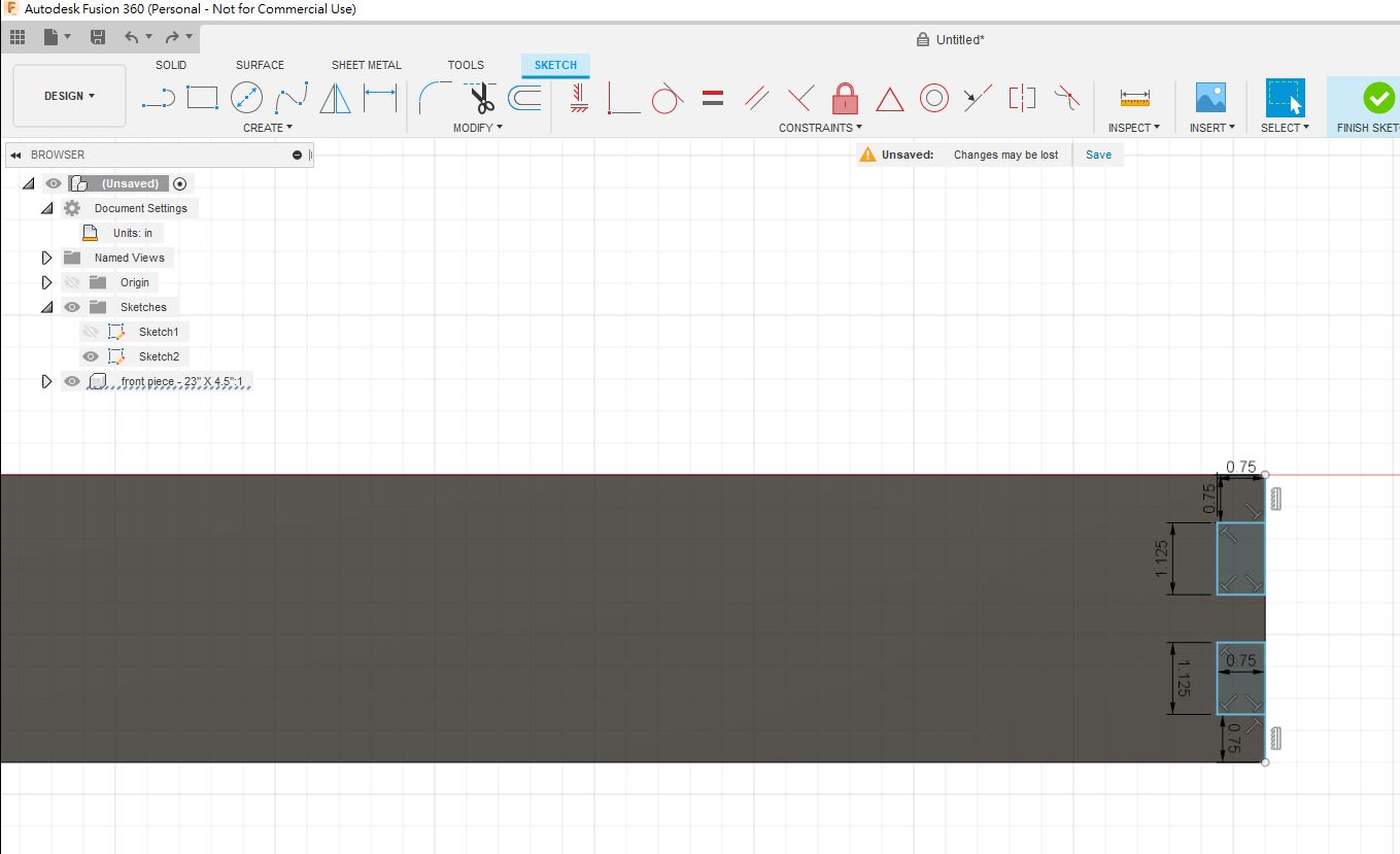
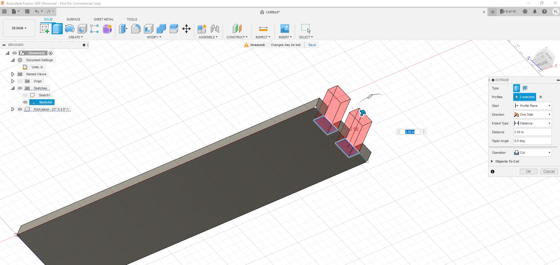
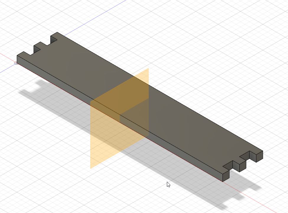
Step 7:
By using “Cut” feature, I can cut the joint like this.
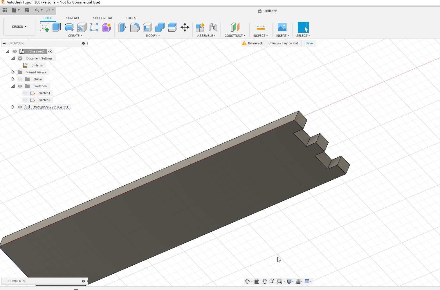
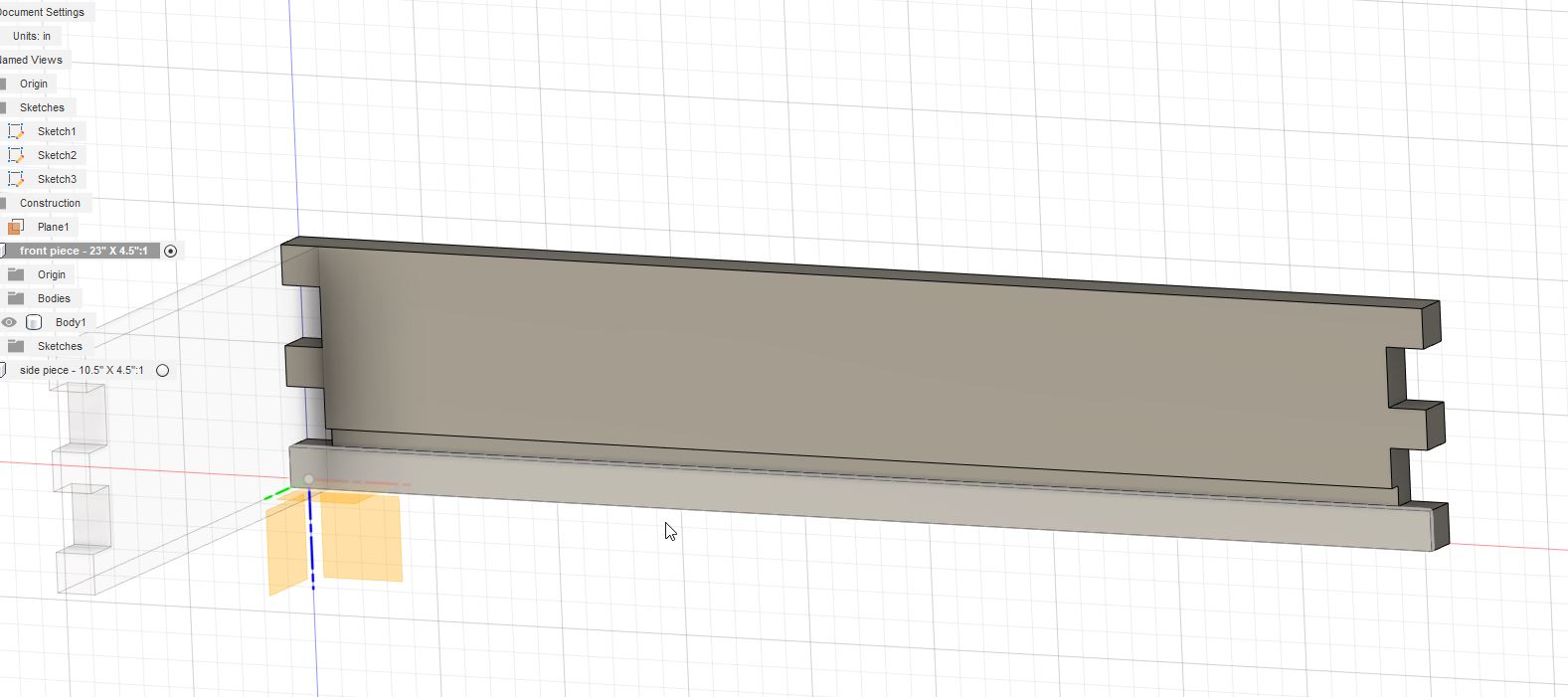
Step 8:
After that, you read that the joint creation are completed.
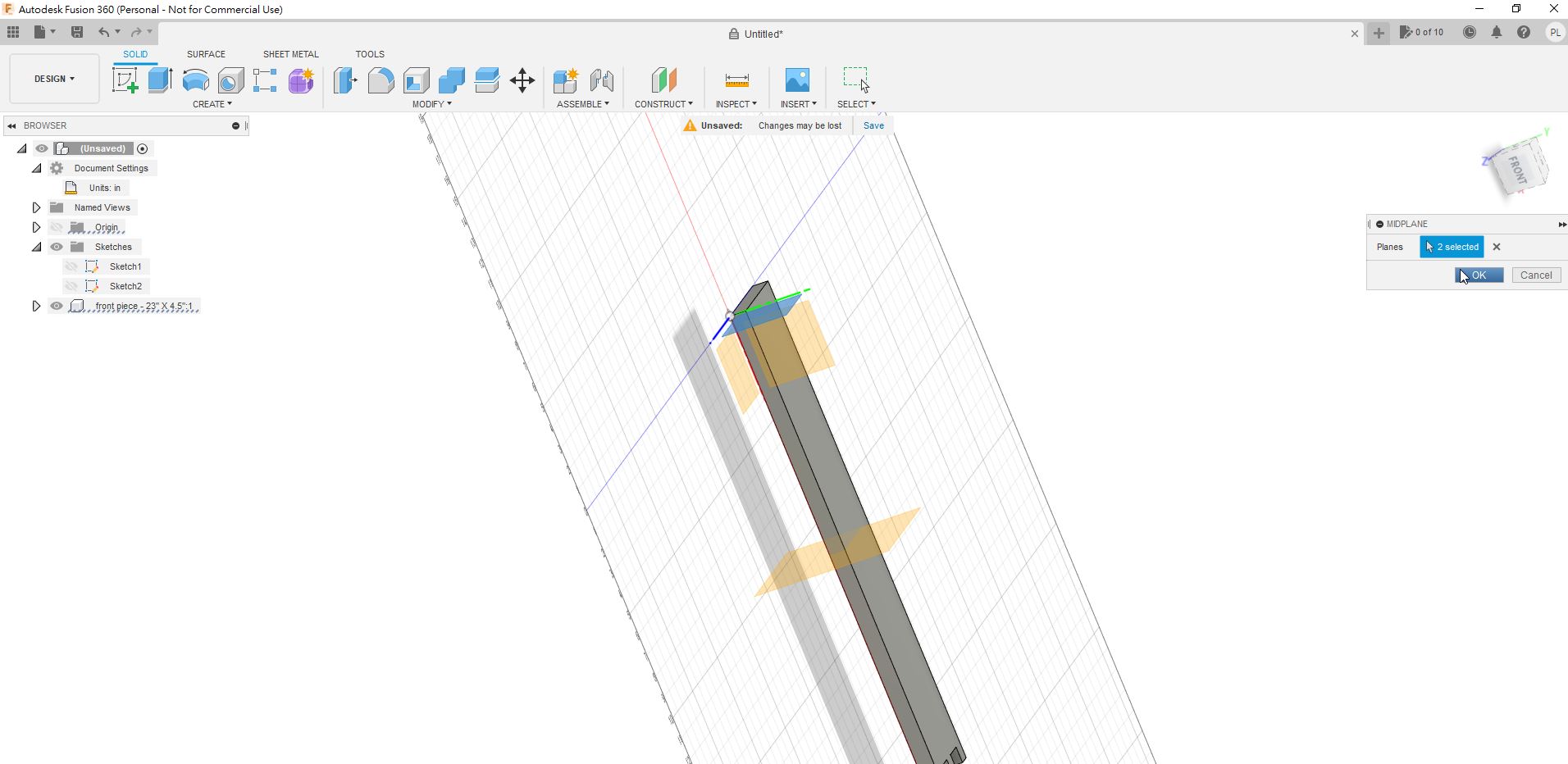
Step 9:
This is a new skill for me, I could use the “midplane” feature to setup a mid plane location.
Step 10:
By using mirror feature, I could mirror the joints to the other side.
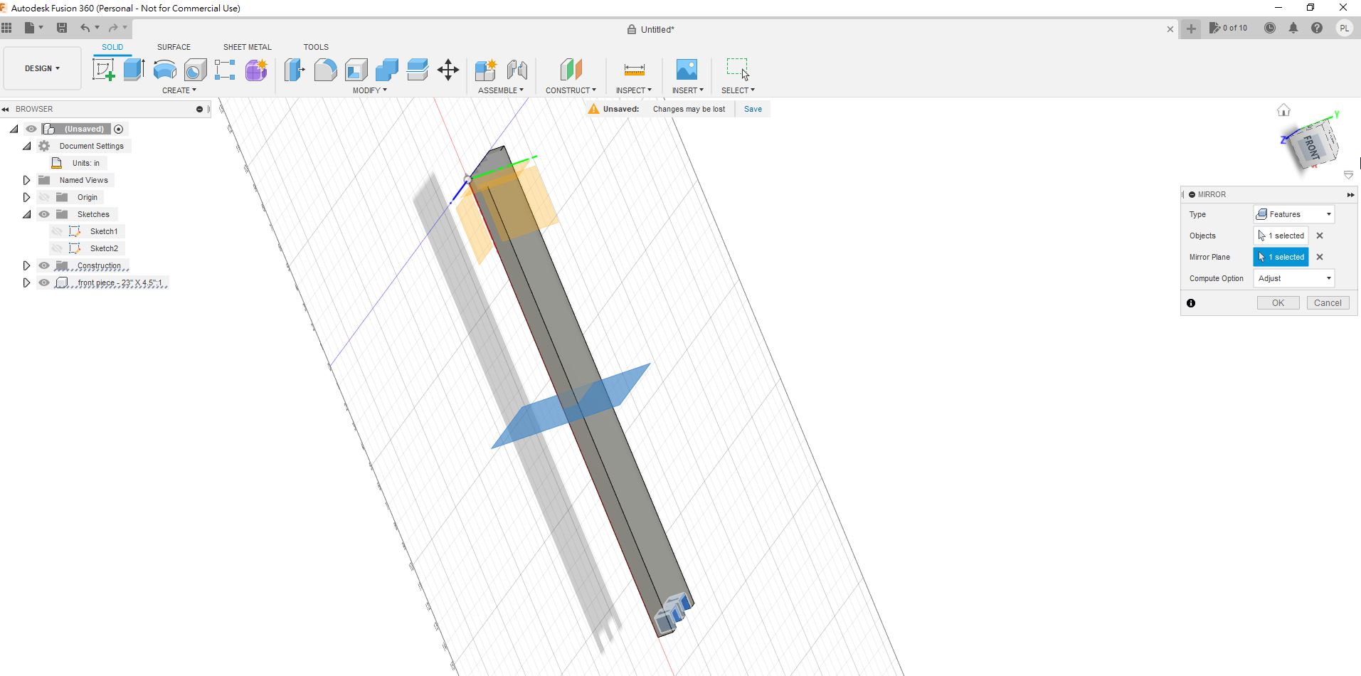
Step 11:
Therefore, both sides are completed.
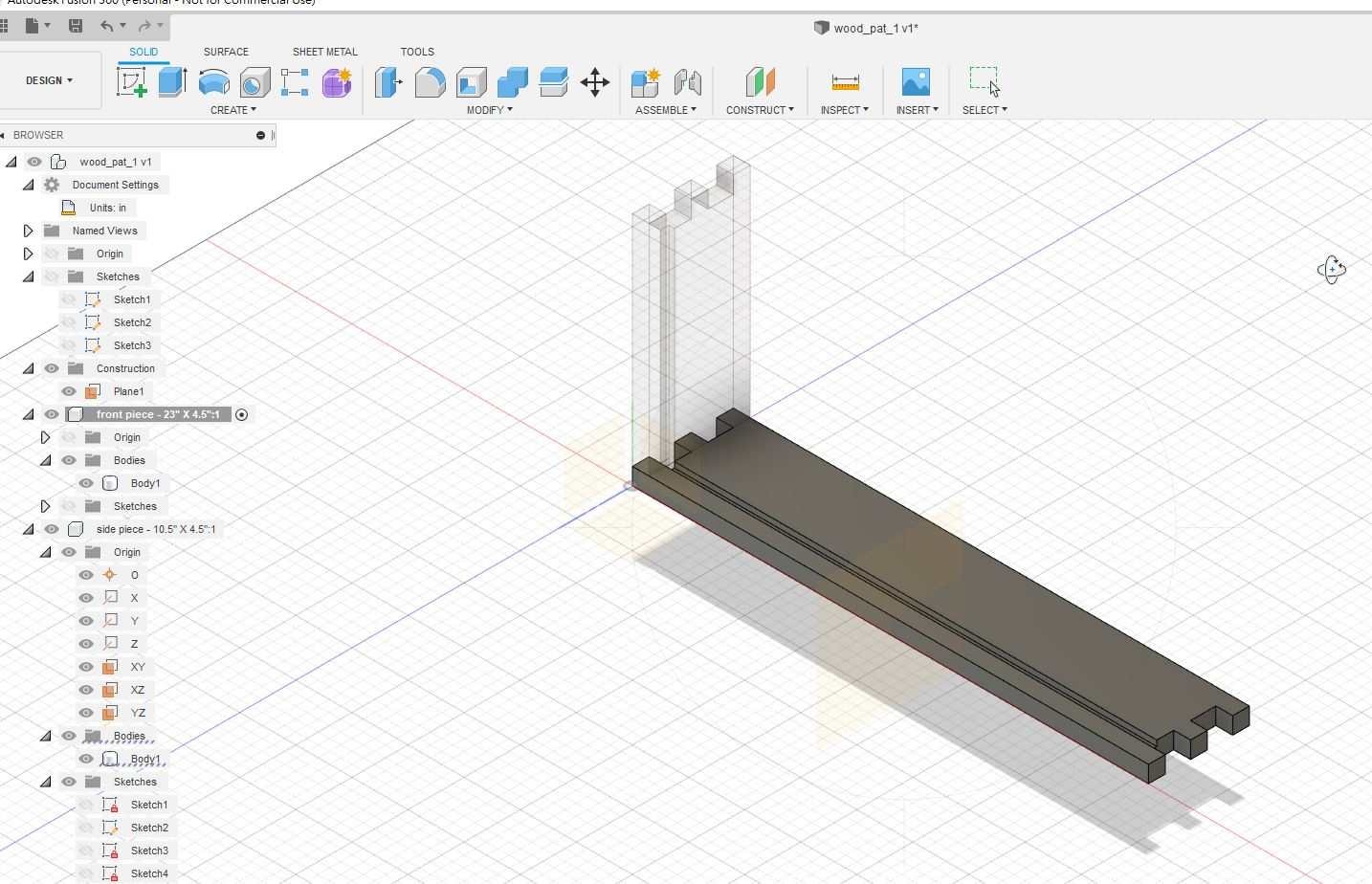
Step 12:
After I have created the front plane, I need to create a side planes.
Step 13:
I have to use “extrude” feature to create this new component.
Step 14:
In the front plane, I need to create a “gap” in the bottom part.
Later I will put a plane on it.
Step 15:
Also in the side plane, I create a “gap” in the bottom part.
Step 16:
I have to use “Mirror” feature again in order to mirror another side plane.
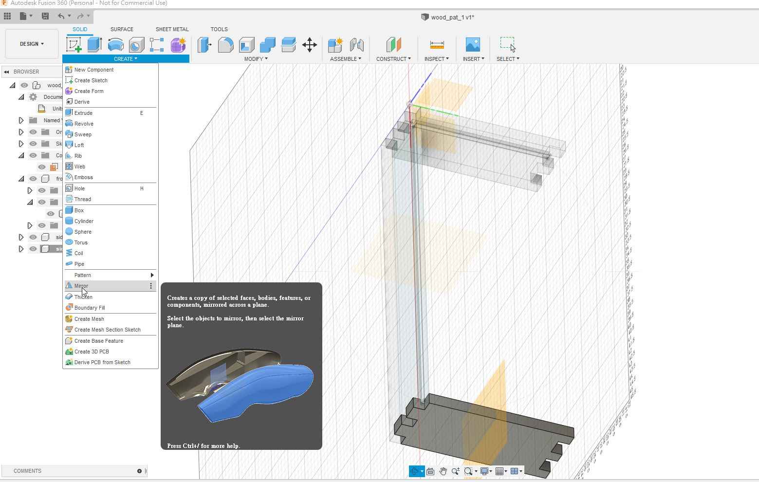
Step 17:
I have learnt that there is another feature which is called “project” to project the “gap ” to the other side.

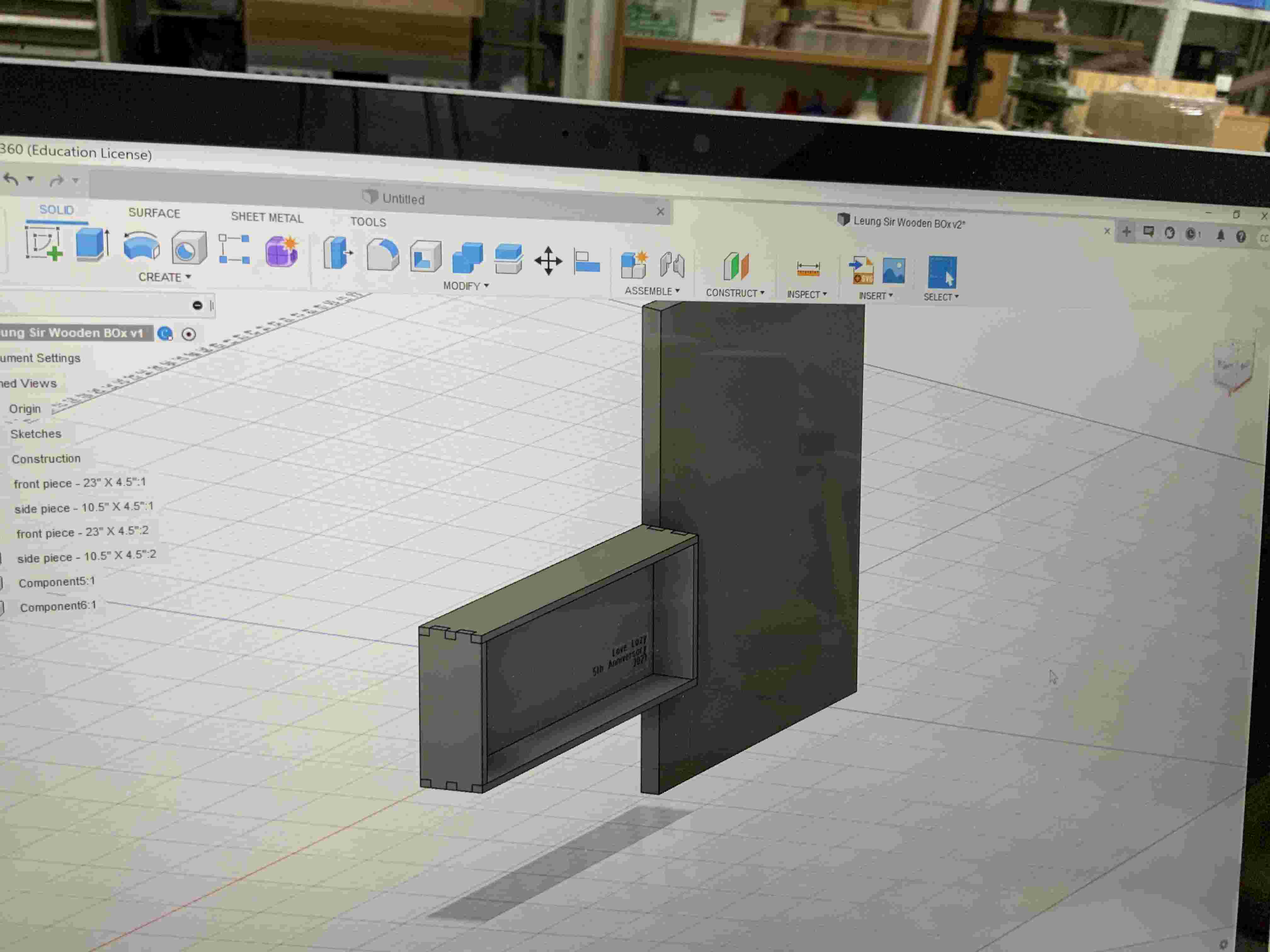
Step 18:
For the plane on the bottom part, I have to extrude it .
You read that the rectangle box are created.
Also, I create a wooden plane that is used to containing each components.
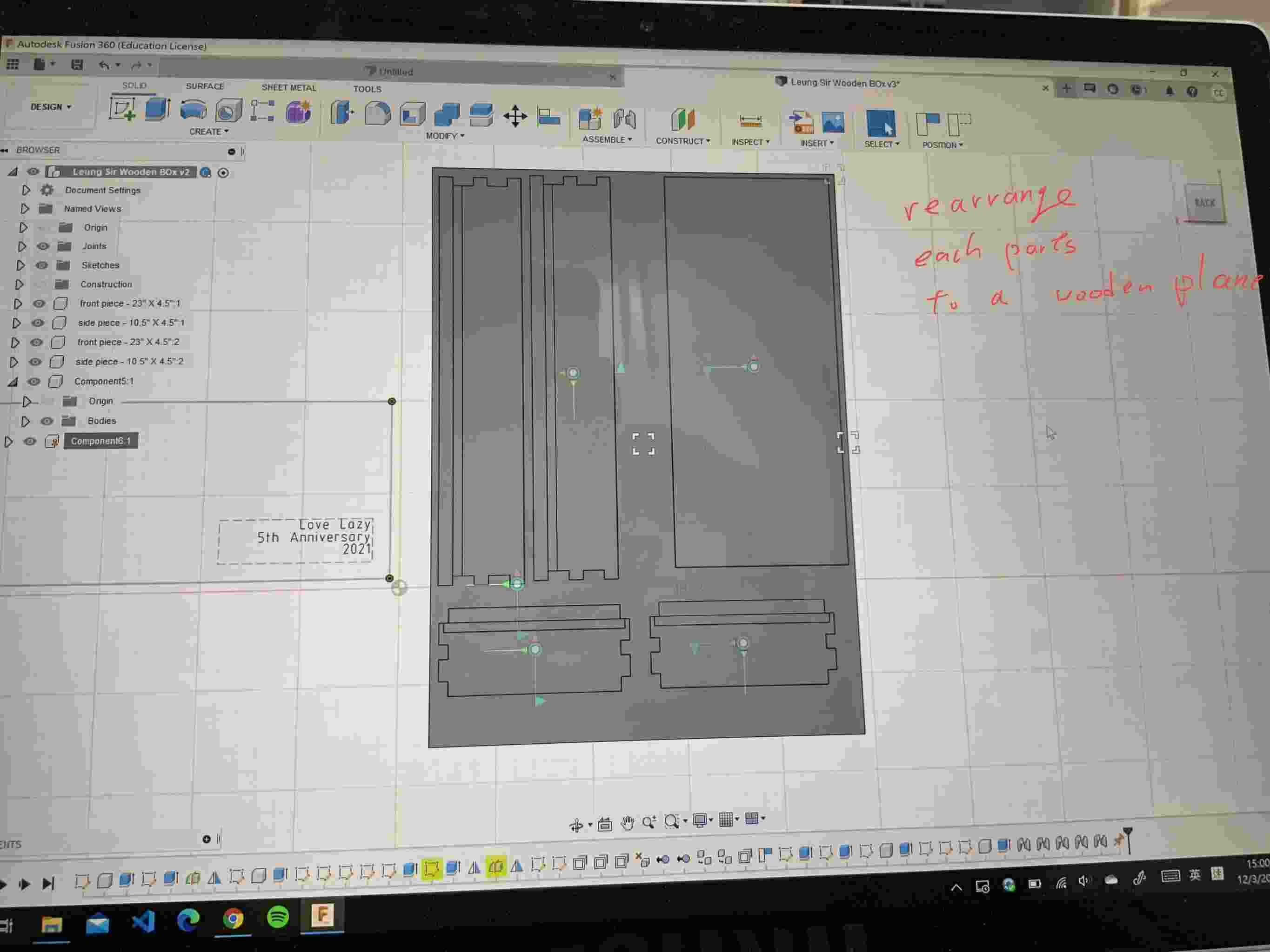
Step 19:
All of the planes are created, that I rearrange each part to a woonen plane location.
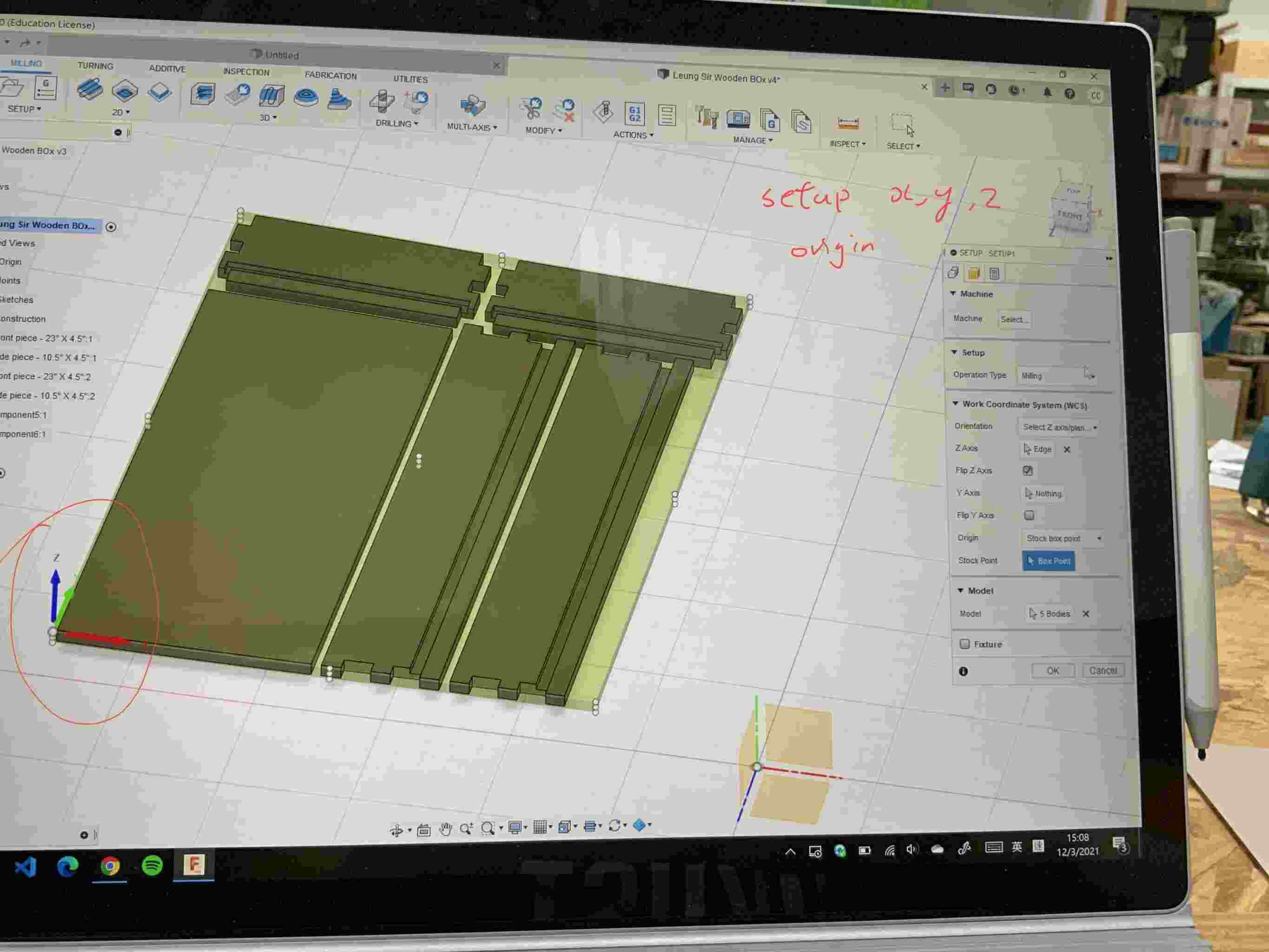
Step 20:
I need to setup the x,y,z origin
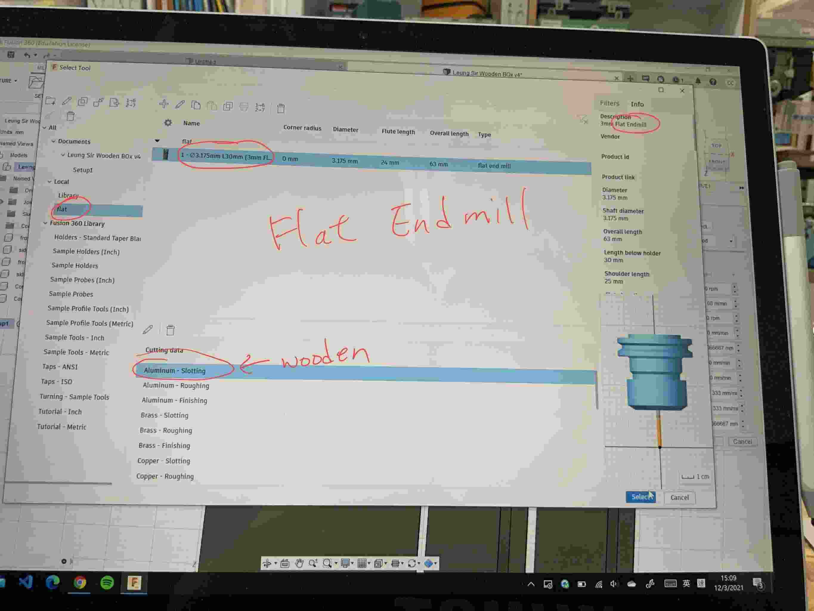
Step 21:
I will use 3mm Flat End mill for creating the components.
The cutting data : I set “aluminum - slotting”
It is because that there is no wood material for me to choose.
Step 22:
I have to use pocket\2D adapative clearing for these four gaps.
The extension method is closest boundary.
![]()
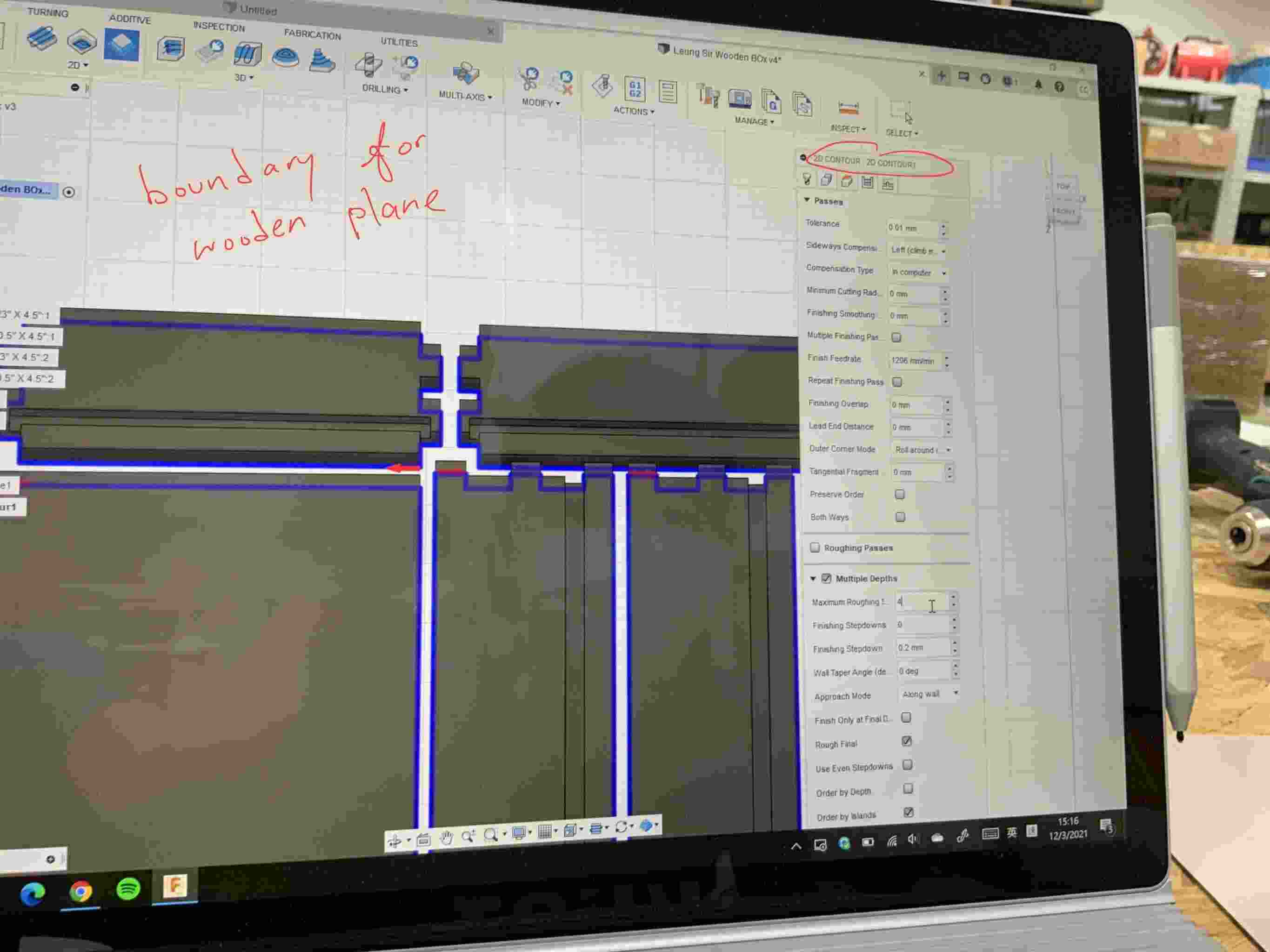
Step 23:
In 2D contour, I setup for the boundary for the wooden plane.
Step 24:
In Fusion 360, there is a simulation for demostrate how is it work later.
Please click on the below video to view the simulation.
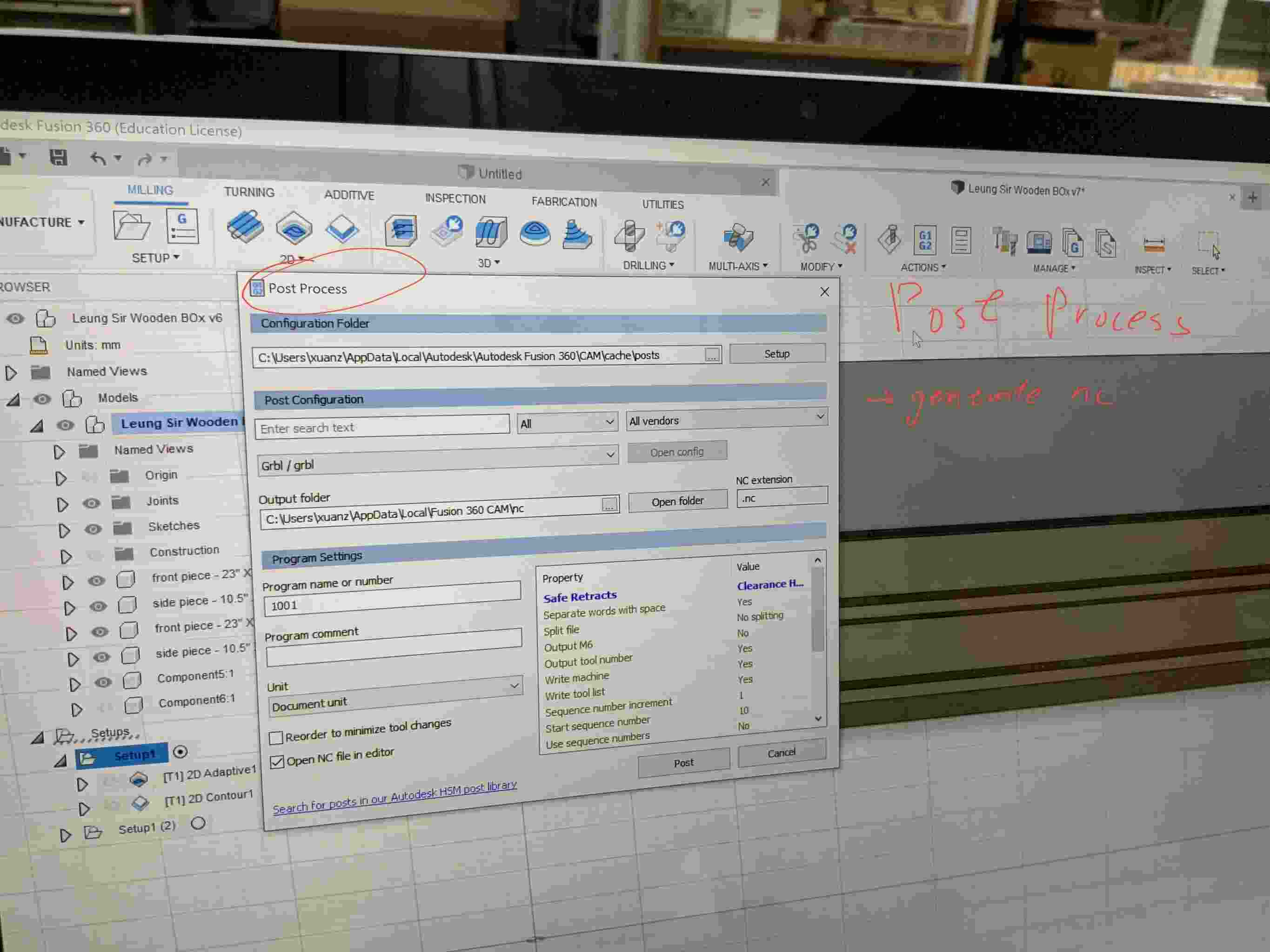
Step 25:
By using Post Process, it is going to generate the g code.
Step 26:
You find that the G code is created.
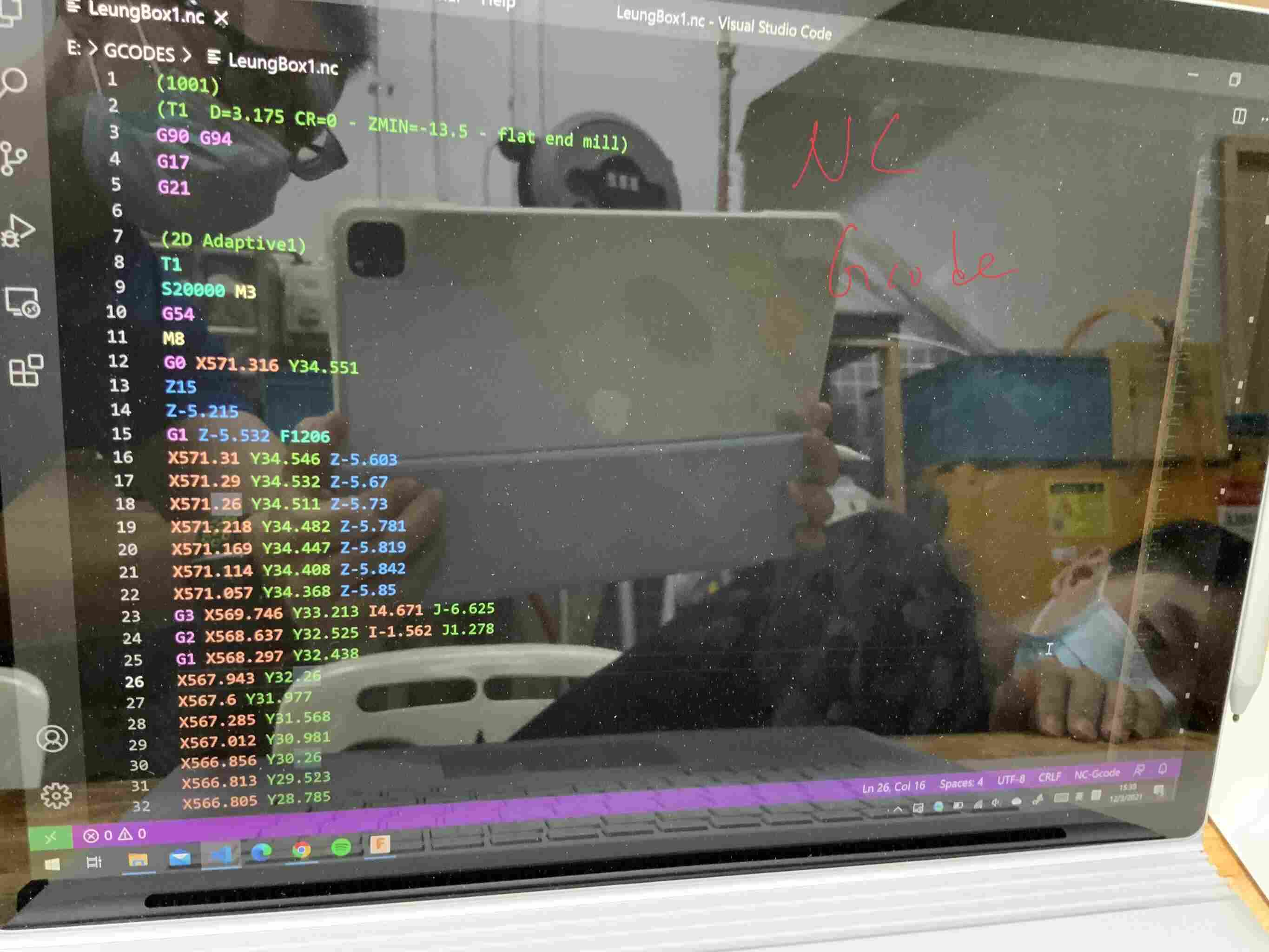
Please click here to download the G code file
Please click here to download the fusion 360 file
Using the computer controlled machining for creating something big.
This is my first time to use this computer controlled machining for wooden project.
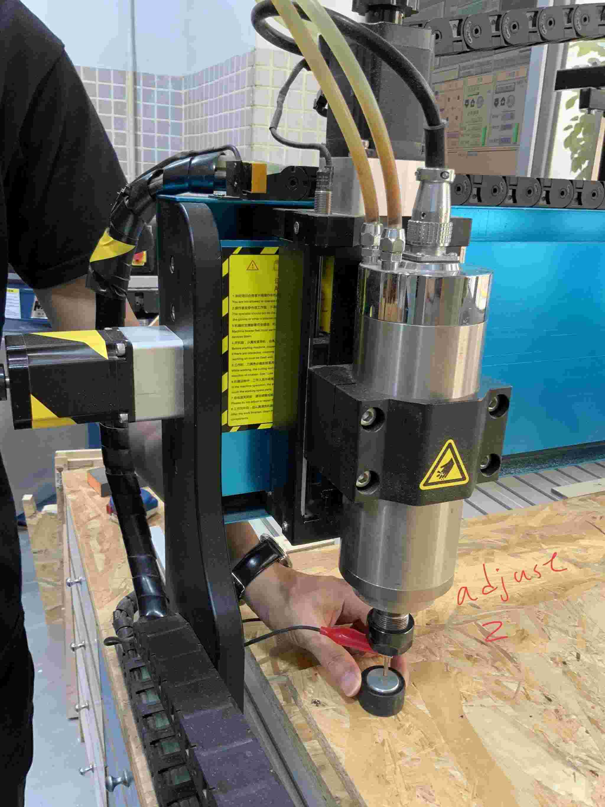
Step 1:
Firstly, I need to adjust the height (z location) of the wooden plane.
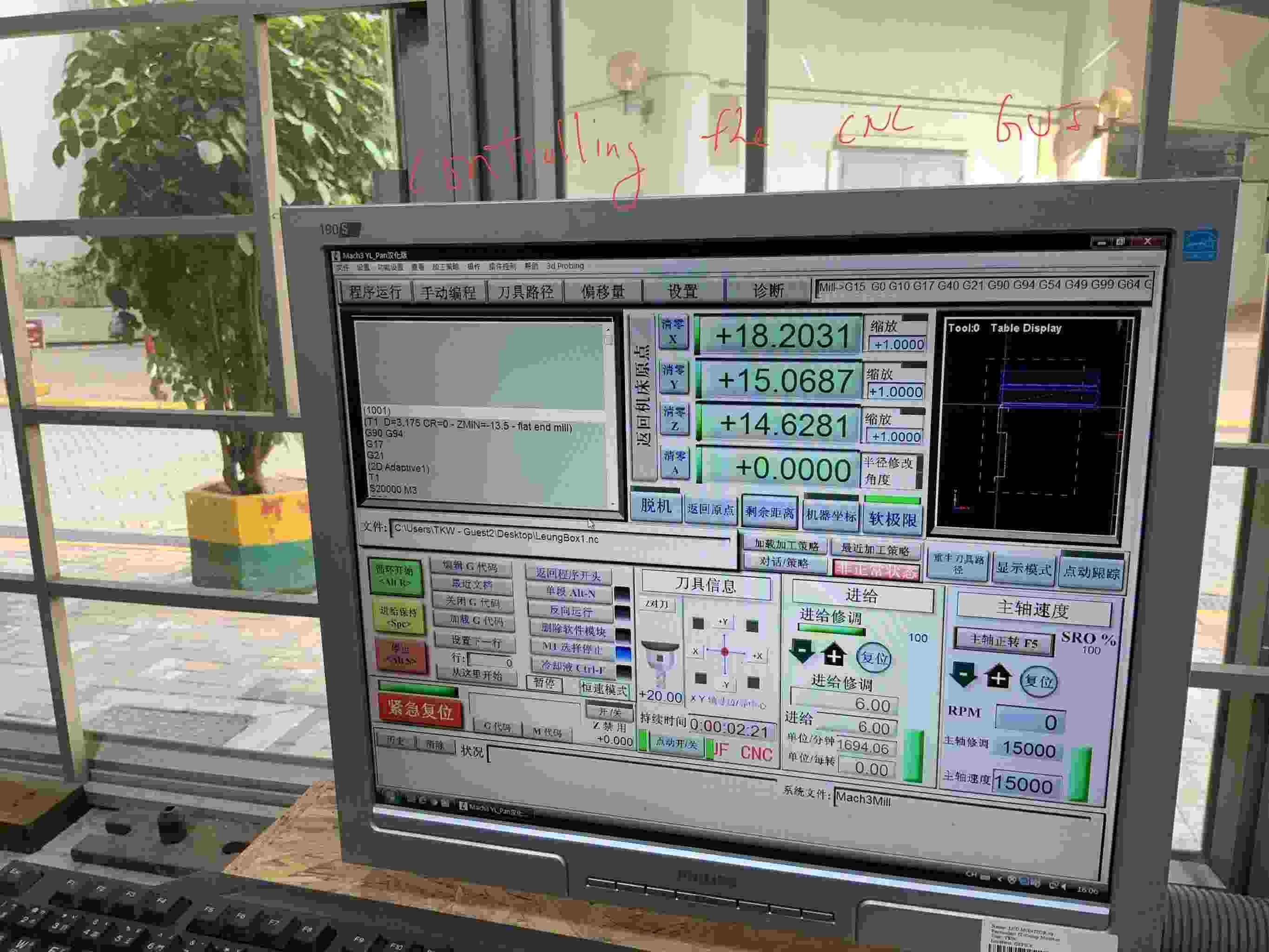
Step 2:
This is the software for controlling the CNC machine.
There was a problem when using this software.
This software cannot read my g code file from USB drive.
After trying many times, I try to restart the PC. Then it is worked again.
The problem is that the PC is too old, the OS window is too old , therefore there is unstable problem.
Software used : Artsoft Mach 3
Step 3:
After starting this machine, you view that it is going to cut the wooden plane out.
Please click on the below video to view the process.
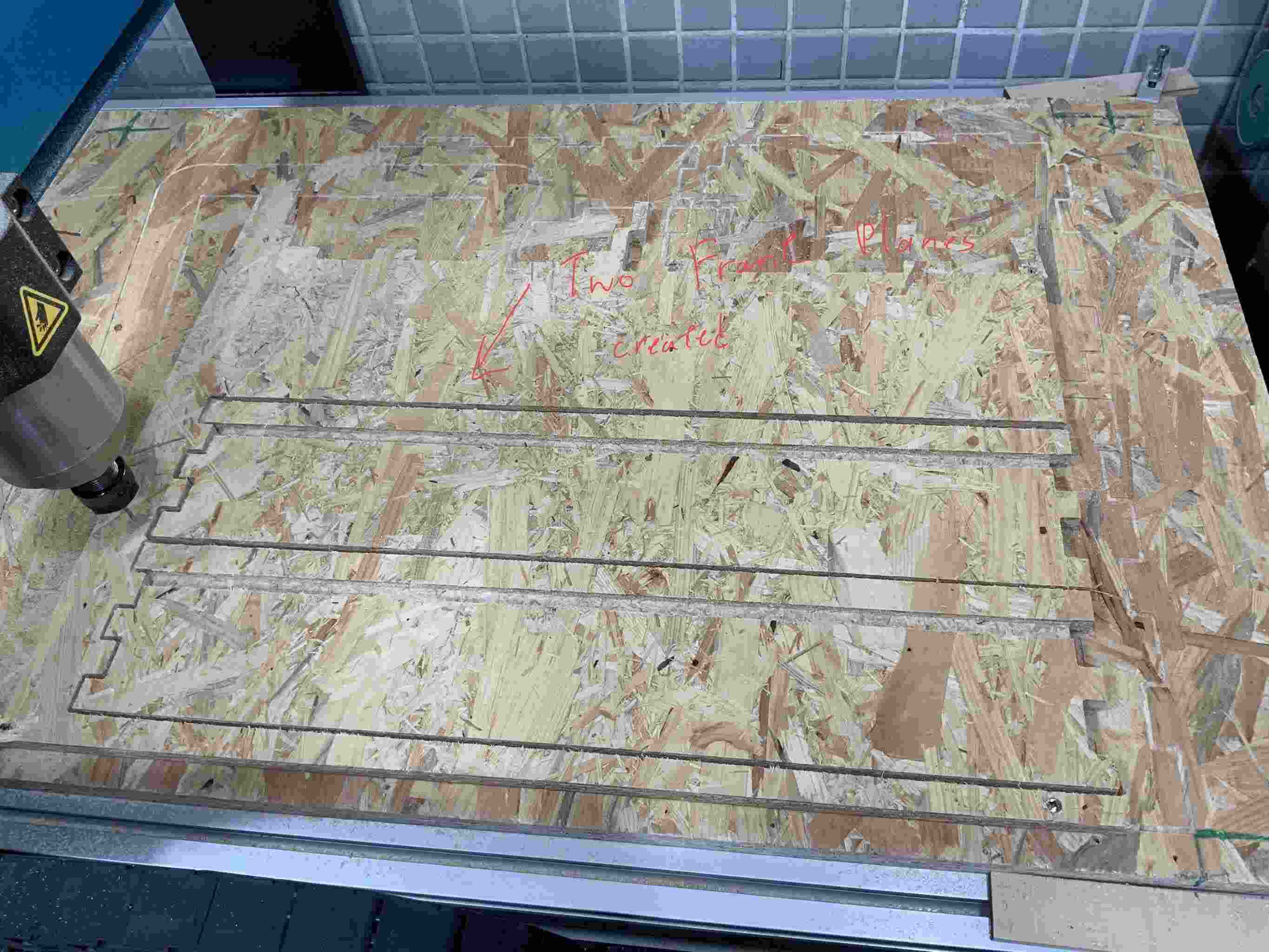
Step 4:
The two front planes are created.
Step 5:
During the process, there are too much dust around it, therefore I need to keep clearning the wooden dust.
![]()
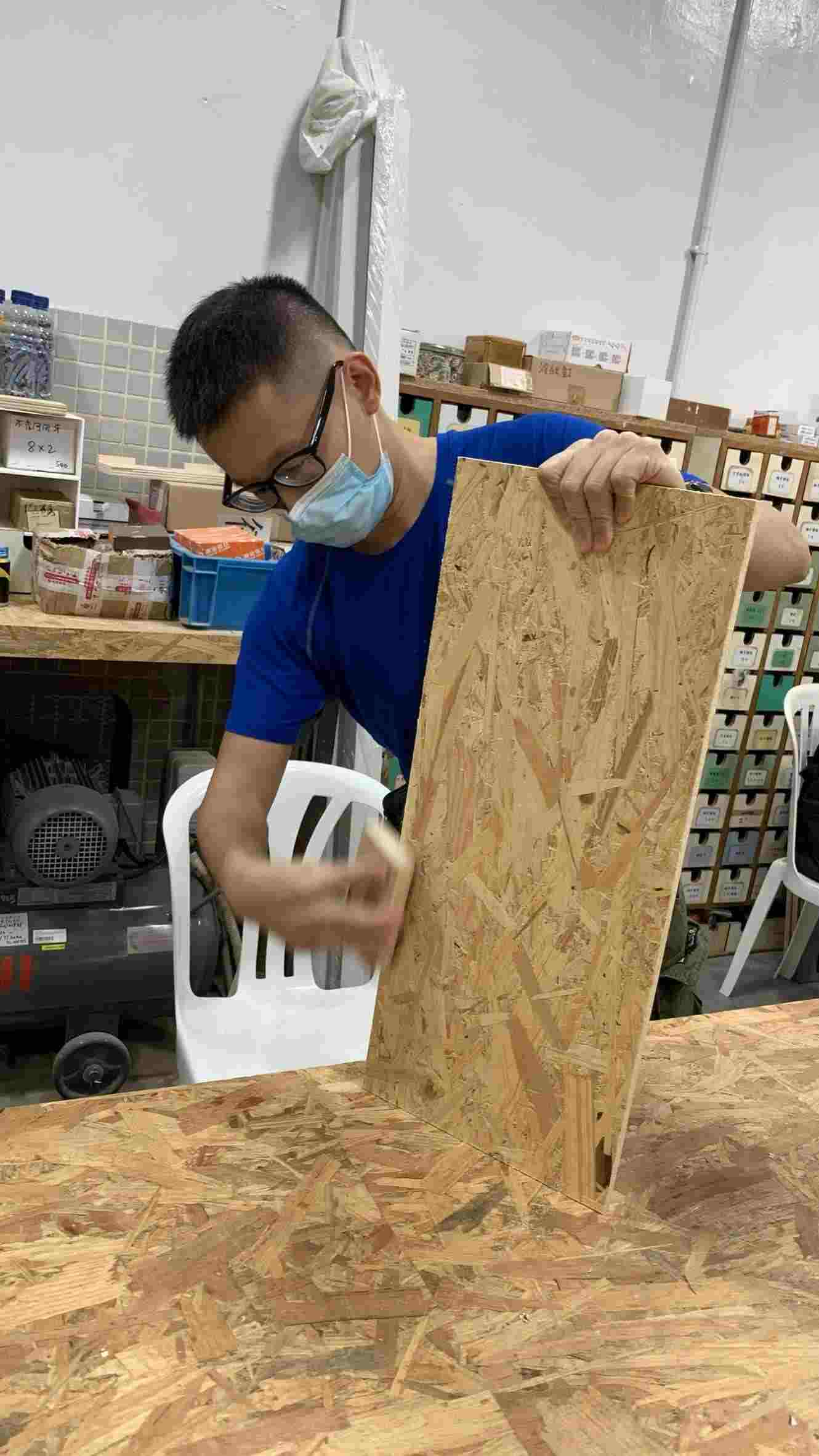
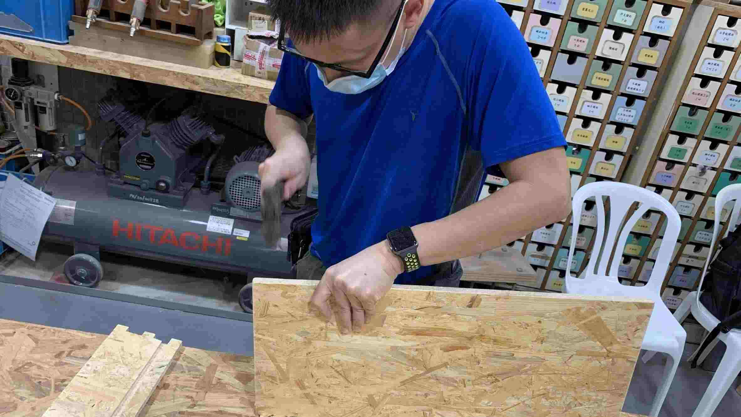
Step 6:
After the wood plane are created, the edge of the wooden plane is too sharp.
Therefore, I need to keep round the edge of the wooden plane.
Step 7:
I try to assembly each wooden plane parts together.
Step 8:
After that , I wooden box are sucessfully created.
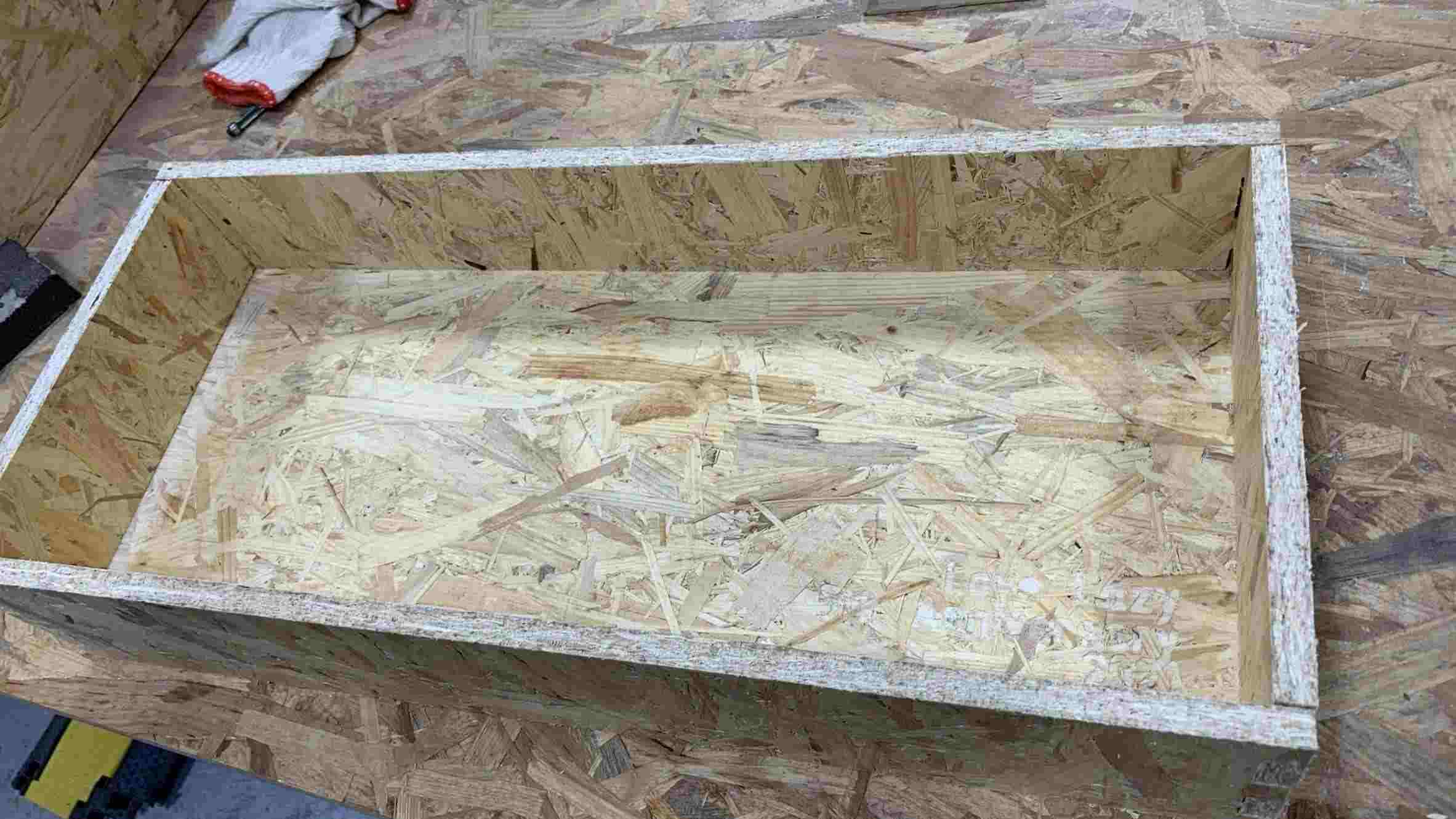
Please click on the below video to view the wooden box.
Group assignments
Test runout, alignment, speeds, feeds, and toolpaths for your machine Document your work (in a group or individually)
Here is the link of the group assignment .