Final Project
This week I worked on defining my final project idea and started to getting used to the documentation process.
Final Project proposal
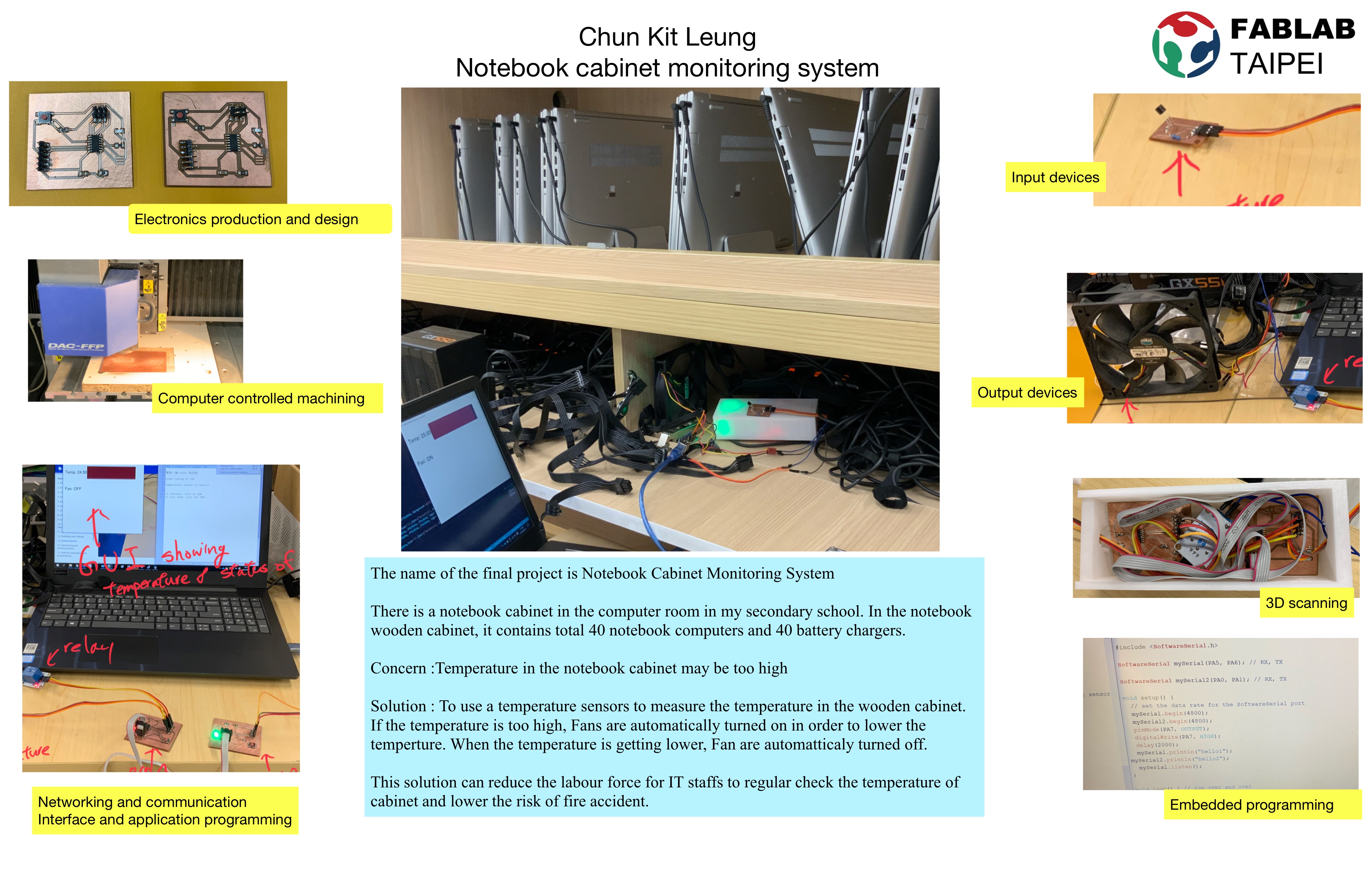
The name of the final project is Notebook Cabinet Monitoring System
There is a notebook cabinet in the computer room in my secondary school. In the notebook wooden cabinet, it contains total 40 notebook computers and 40 battery chargers. Notebooks computers are taken out when students attending computer lessons. After computer lesson, students need to put notebook computers back to the wooden cabinet.
There is a major concerns we are facing it now. Also, a solution is provided.
Concern :Temperature in the notebook cabinet may be too high
Since it is a wooden cabinet. When all notebook computers are charging electricity in the wooden cabinet. The 40 notebook computers and 40 battery chargers may be too high temperature in a wooden cabinet. Too high temperature may cause fire accident or affect the performance of notebook computers and batterys.
Solution :
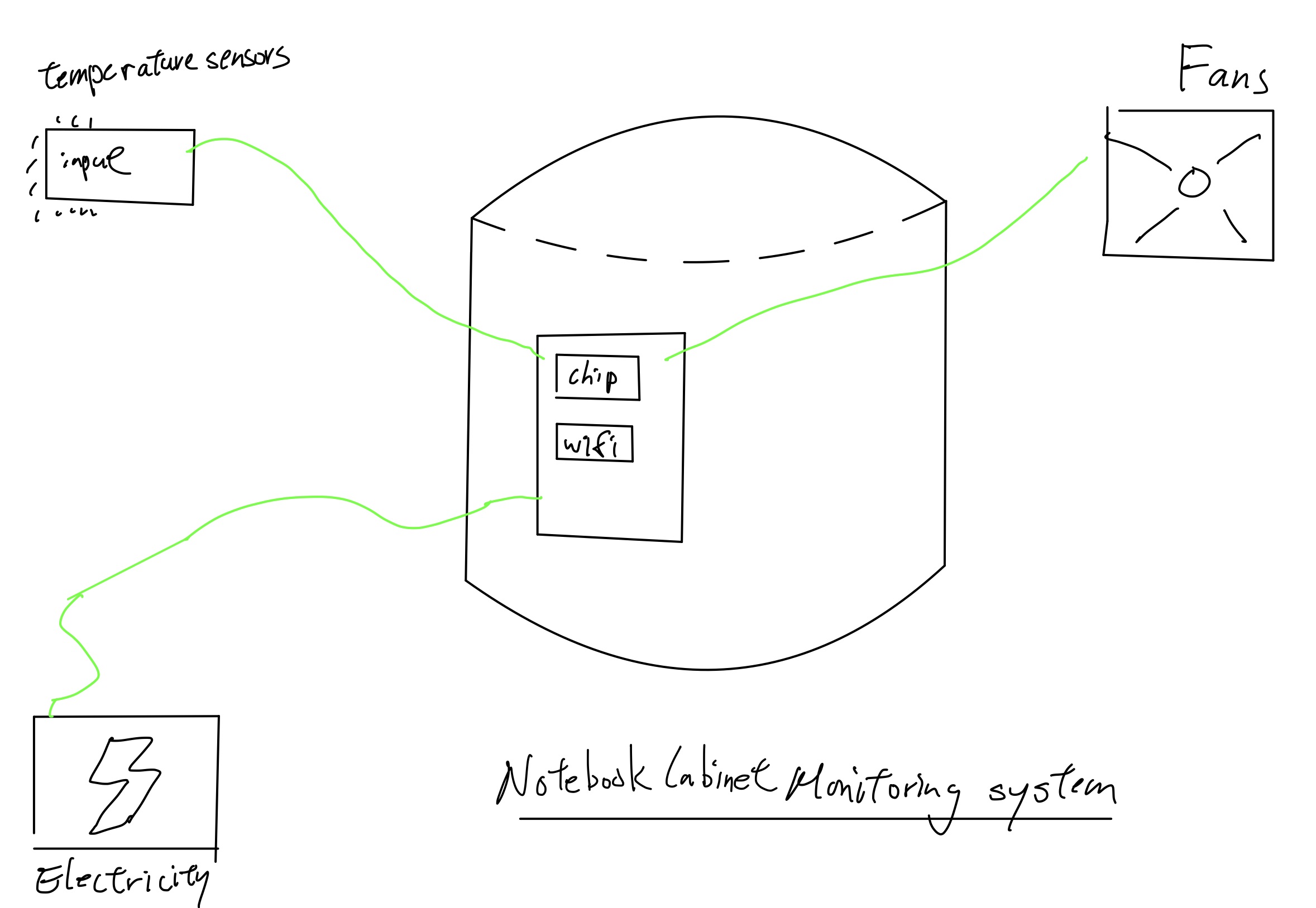
To use a temperature sensors to measure the temperature in the wooden cabinet. If the temperature is too high, Fans are automatically turned on in order to lower the temperture. Also, a real time notification will be sent to IT staffs and computer teacher in order to notifiy them.
When the temperature is getting lower, Fan are automatticaly turned off.
This solution can reduce the labour force for IT staffs to regular check the temperature of cabinet and lower the risk of fire accident.
An initial sketch of the final project
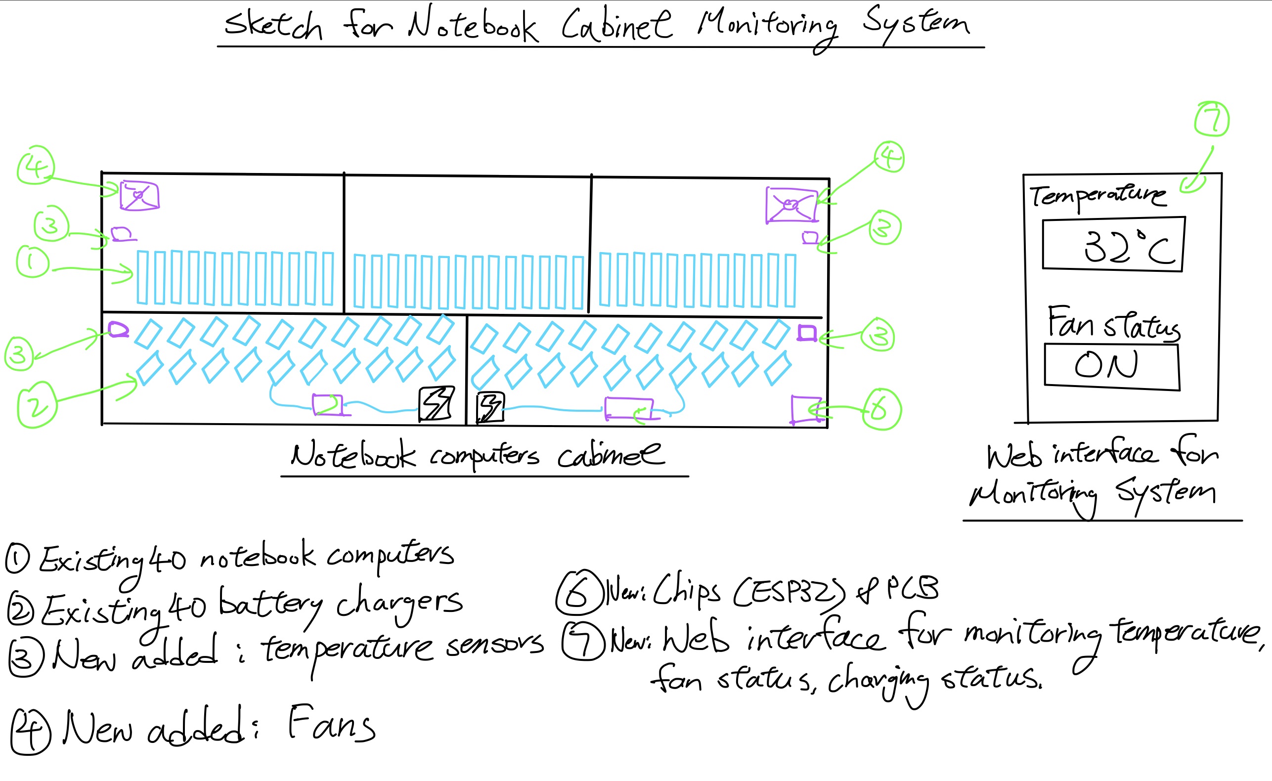
An initial sketch of Notebook Cabinet Monitoring system
Who will use the Notebook Cabinet Monitoring system
IT staffs and computer teacher will use the system. Therefore administrative cost and time for IT staff can be reduced.
electronincs production and design
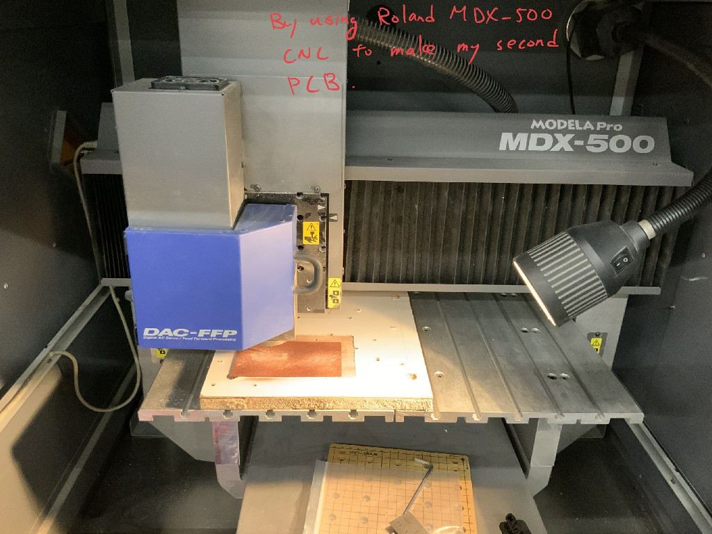
By using Roland MDX-500 CNC to make my second PCB.
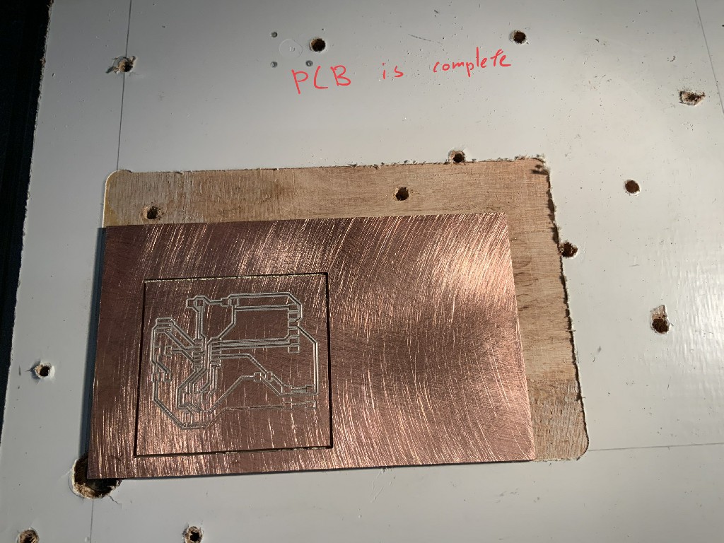
The milling of PCB is finished.
By using Roland MDX-500 CNC to make my second PCB.
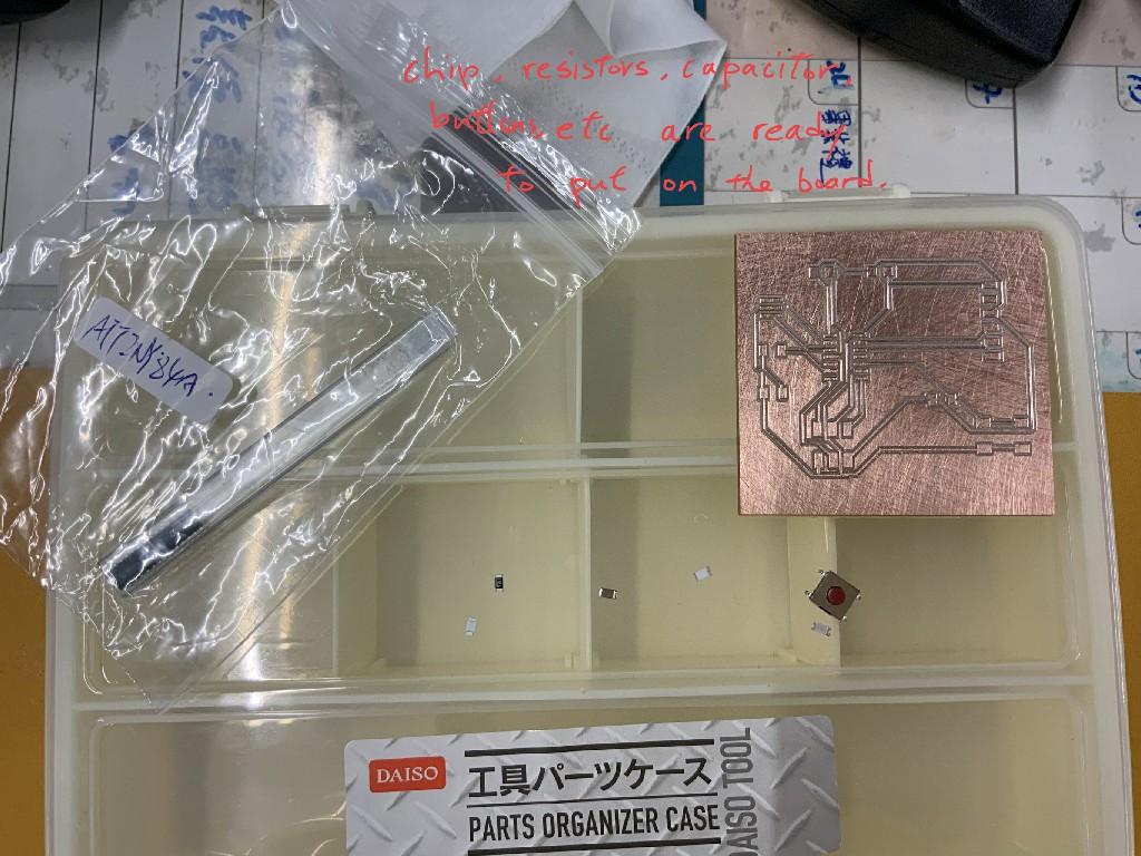
Chips, resistors, capacitor, buttons etc are ready to put on the board.
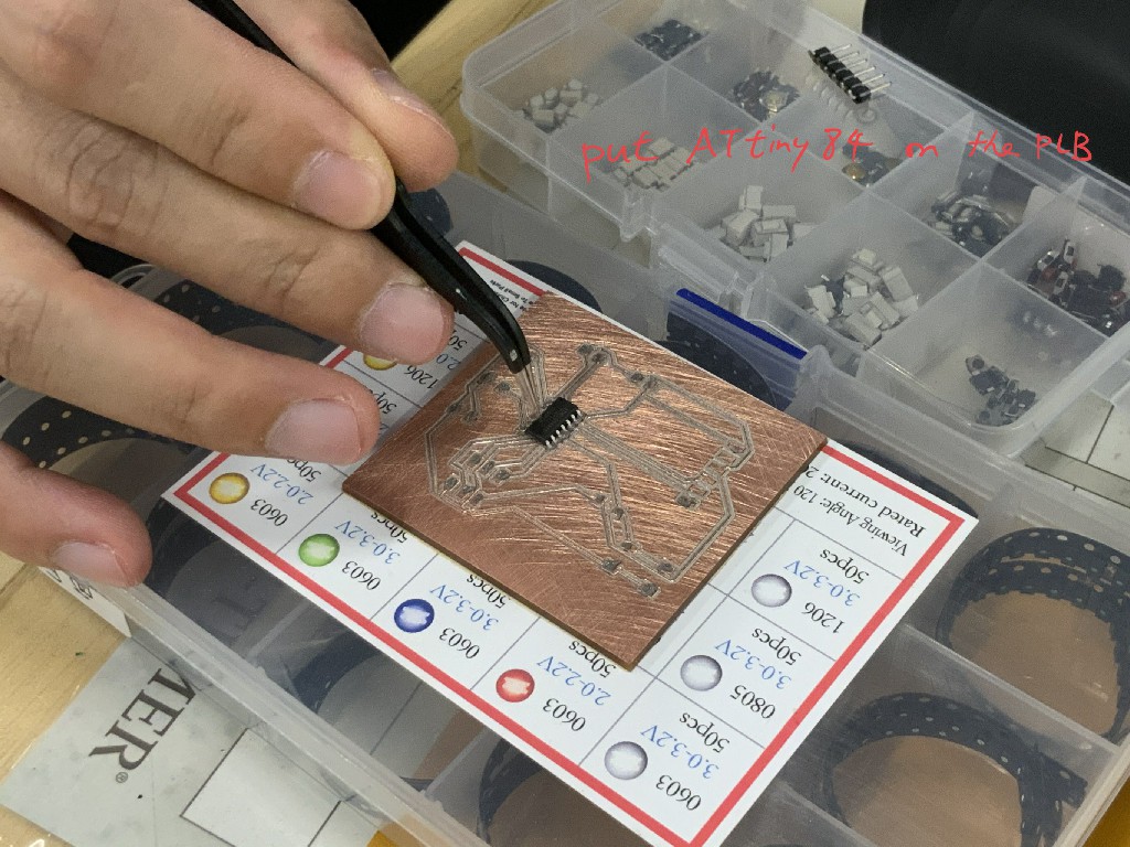
Put Attiny84 on the PCB.
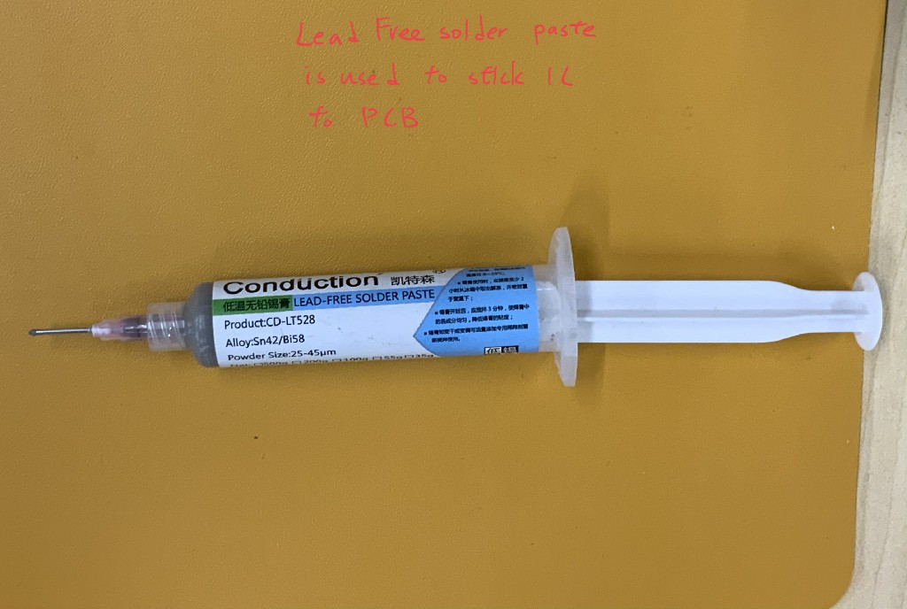
Using the lead free solder paste to stick IC to PCB.
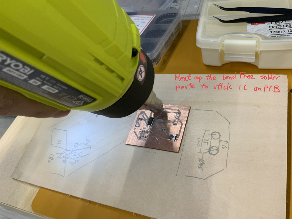
Heat up the lead free solder paste to stick IC on PCB.
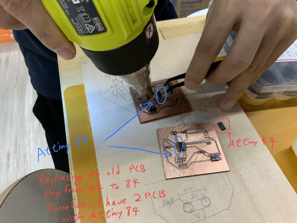
Replacing my old PCB chip from Attiny 44 to Attiny84.Therefore I have 2 PCB with Attiny84.
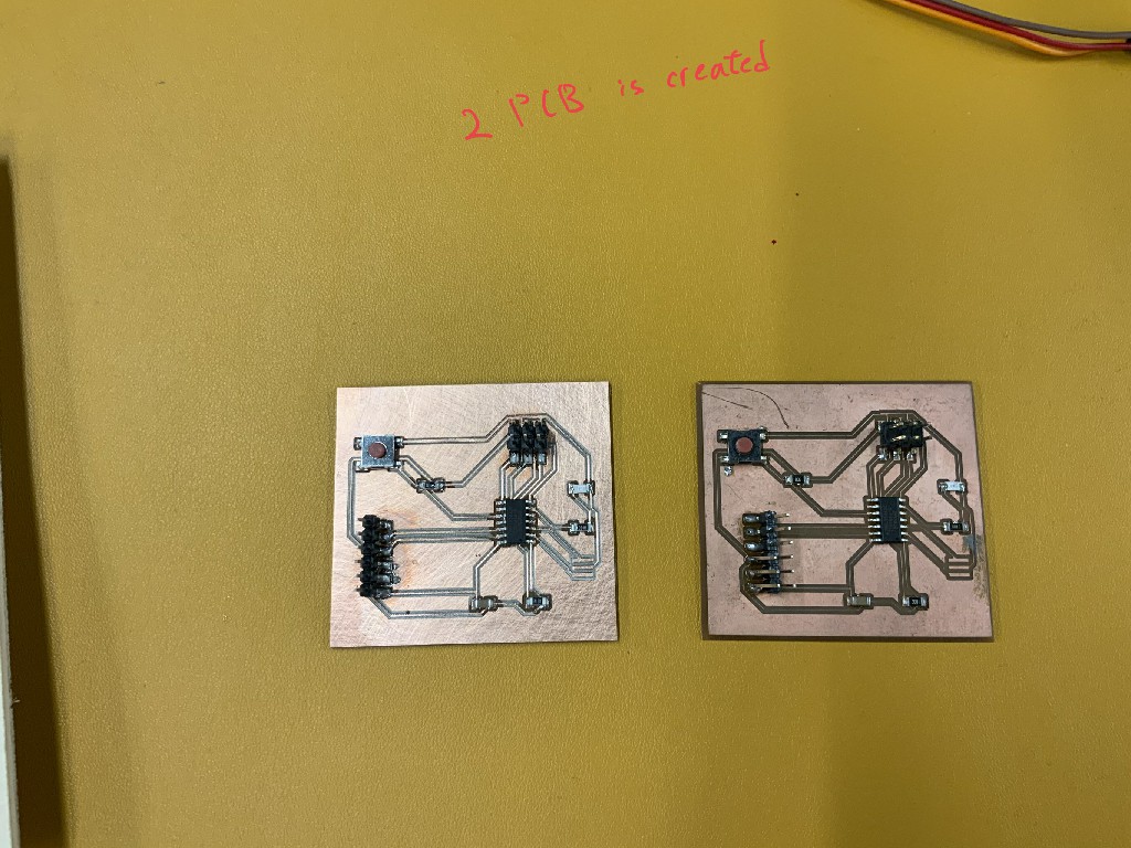
Two PCB are created.
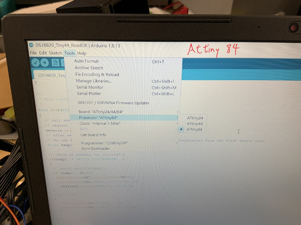
In arduino, I need to chhose processor Attiny84.
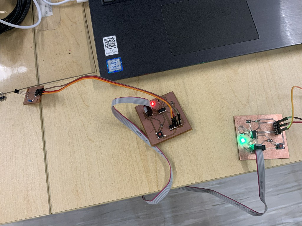
There are two PCB. The first PCB A (with red LED) receive input signal from input sensors.
Then, the serial signal is transferred to my second PCB B (with green LED).
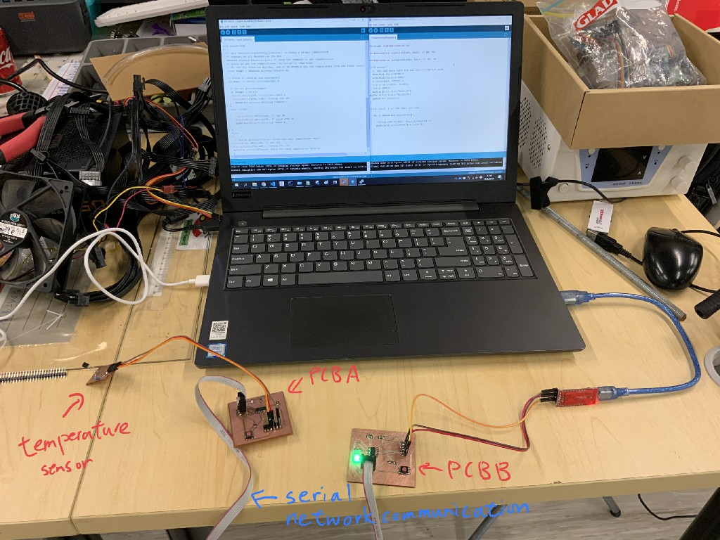
The whole picture of every part of my final project.
Temperature senors on the left hand side.
A serial network communication is used as a transmission channel.
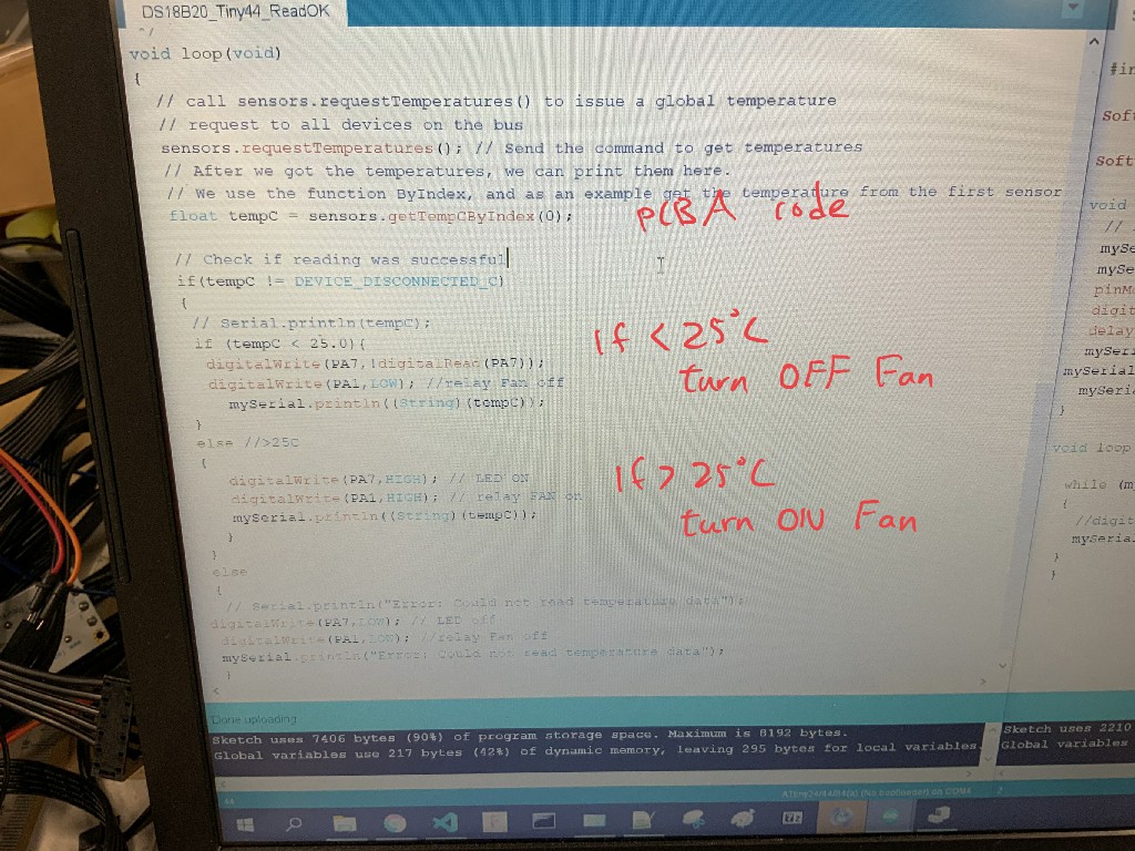
code of PCB A.
If temperature is lower than 25C, turn off Fan.
If temperature is higher than 25C, turn on Fan.
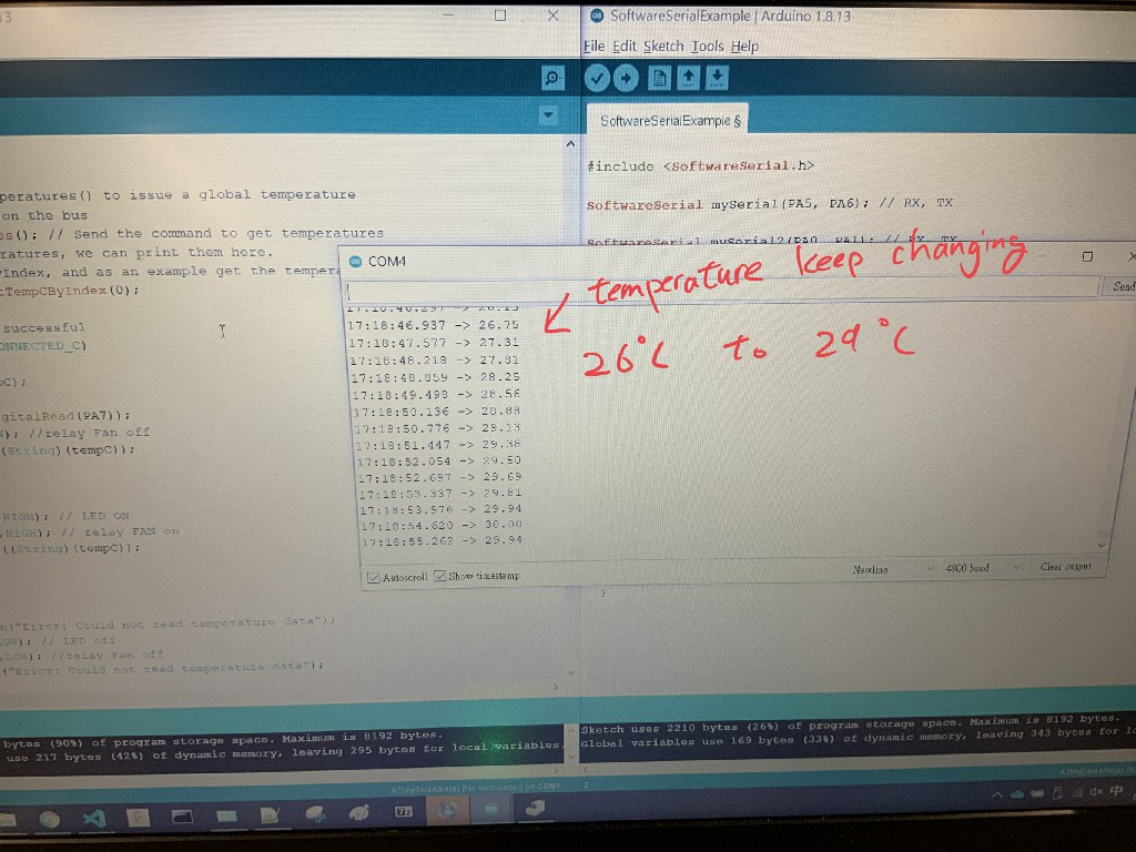
In serial monitor, temperature keep changing from 26 C to 29C.
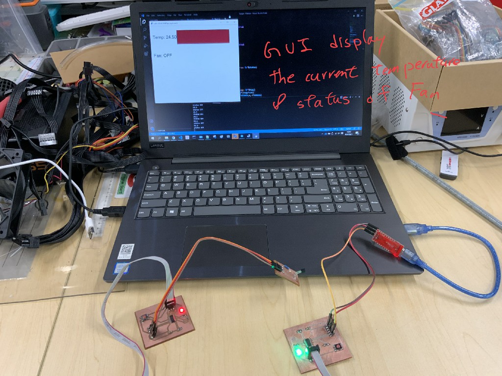
GUI display the current temperature and status of Fan.
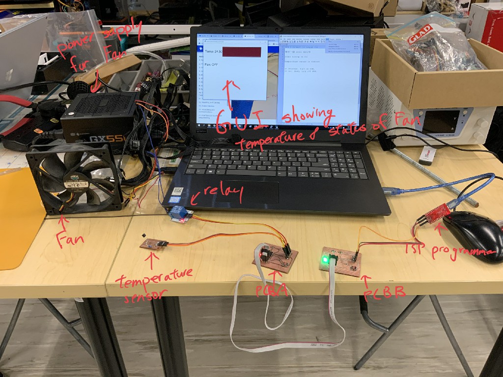
Here is every parts of my project.
Here is my final poster
This is the video of my final project
Here is my final project files
Please click here to download the ino file
Please click here to download the ino file
Please click here to download the python file
Please click here to download the schematic file
Please click here to download the broad file