7. Electronics design
This week task as below:
- Individual assignments
Redraw the echo hello-world board. Add (at least) a button and LED (with current-limiting resistor), check the design rules, make it, and test it. Extra credit: simulate its operation.
Eagle
Eagle , the full name is : Easily Applicable Graphical Layout Editor, it is used to draw an expandable EDA schematic , PCB layout, also, auto route.
This is my first time to use Eagle.
Step 1: Download Eagle from the following link. - Eagle
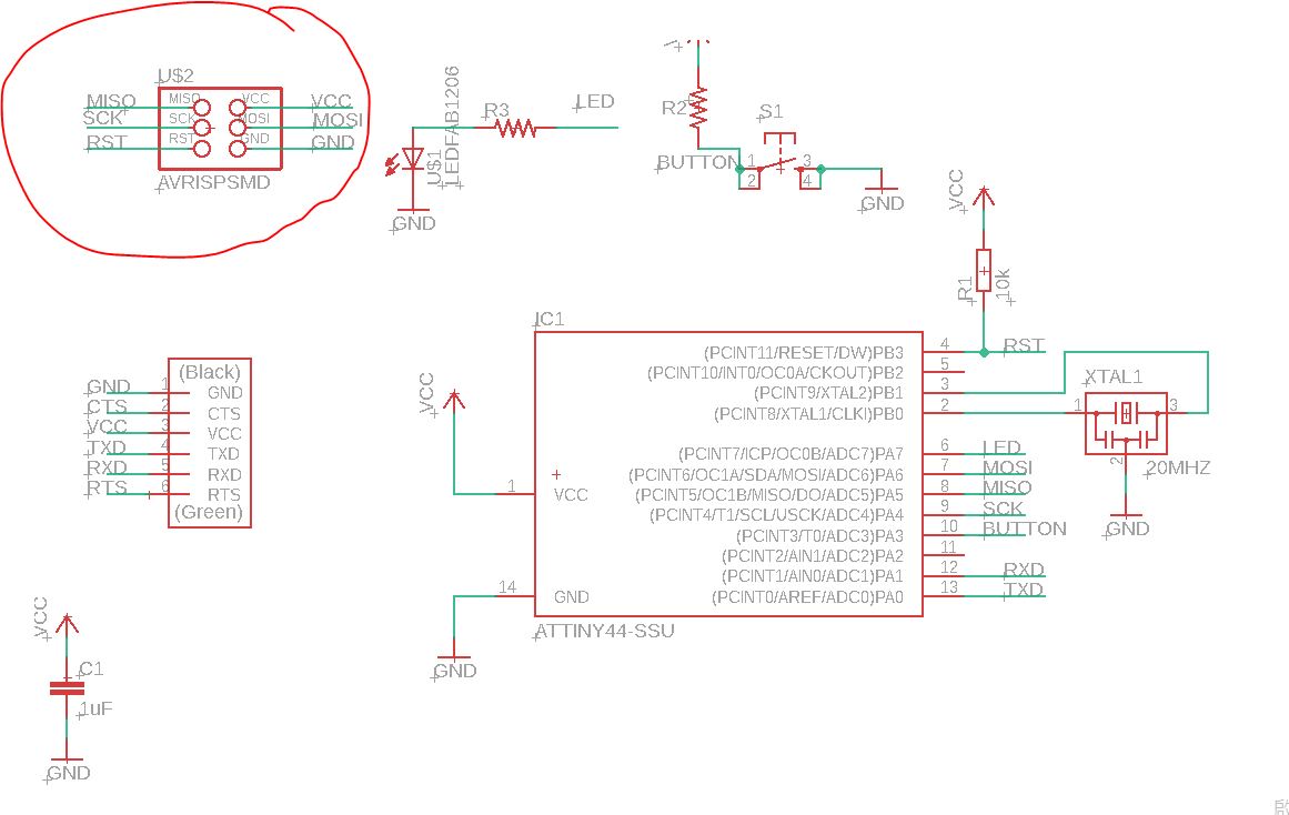
Step 2: After installing the Eagle and open the hello.fdti.44 schematic from Fab Academy.

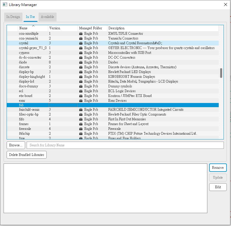
Step 3: Also, I have downloaded the Fab.lib from Fab Academy. It can enrich the components that I will use them in Eagle.
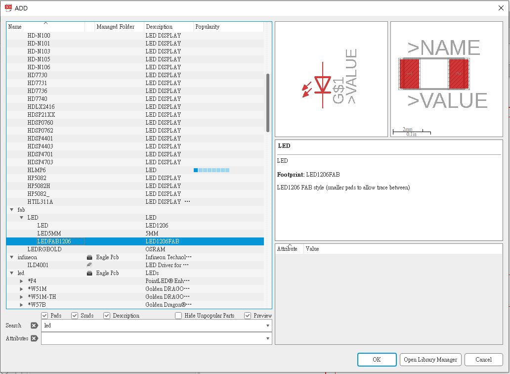
Step 4: Now I am going to add a LED FAB 1206 component
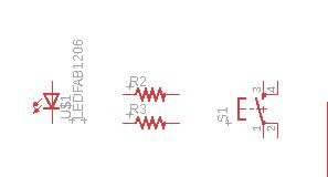
Step 5: By using Fab Library, I have also added two resistors and one button as below.
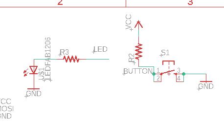
Step 6: In Eagle, I need to to use net, name feature in order to assembly the LED and switch component in the schematic.
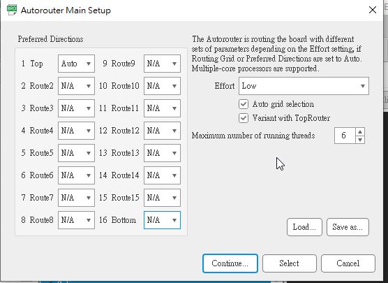
Step 7: After changing to board view, I want to use auto router to route my diagram.
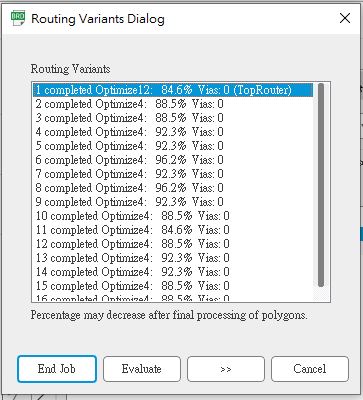
Step 8: This is the auto router result. You may read that the top router is 84.6%. It can not achieve 100%.
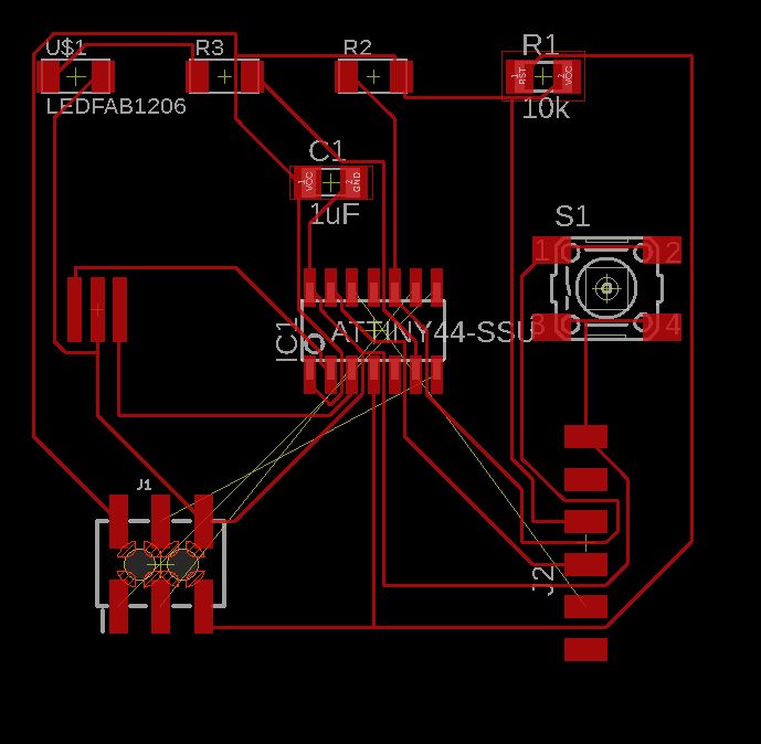
Step 9: This is the board view. but I find that there are some problem “yellow lines” mean that those connection are not connected.
Step 10: Therefore I have adjust the schematics diagram. I have changed this component.
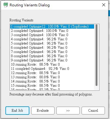
Step 11: After I have tried several times auto router. I have gotten a 100 % routing result as below.
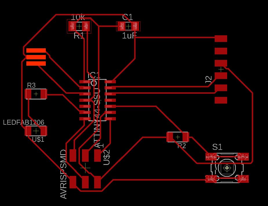
Step 12: This is the final board view. It look pretty nice right now
Please click here to download the schematic file
Please click here to download the board file
Step 13: I have to use eagle DRC to check if there is no error.
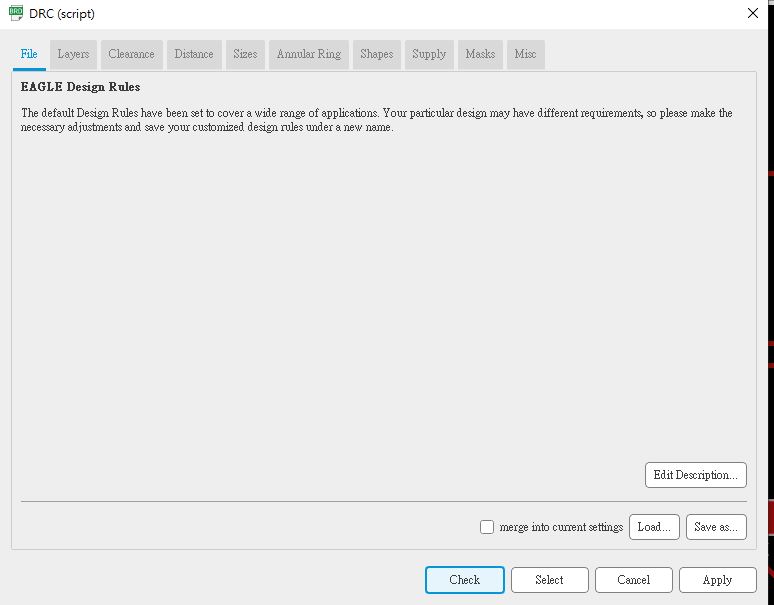
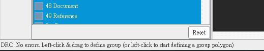
Step 14: After uploading the DRC script from Fab lab tutorial. Fortunately, there is no errors found.
Step 15: I only choose the top layer as the export file. Also, I choose export\iamge\png in order to export png file.
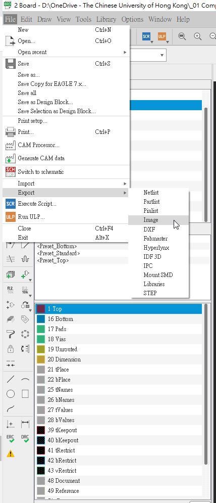
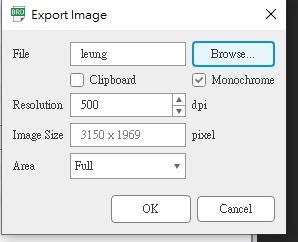
Step 17: This is the export iamge setting as below
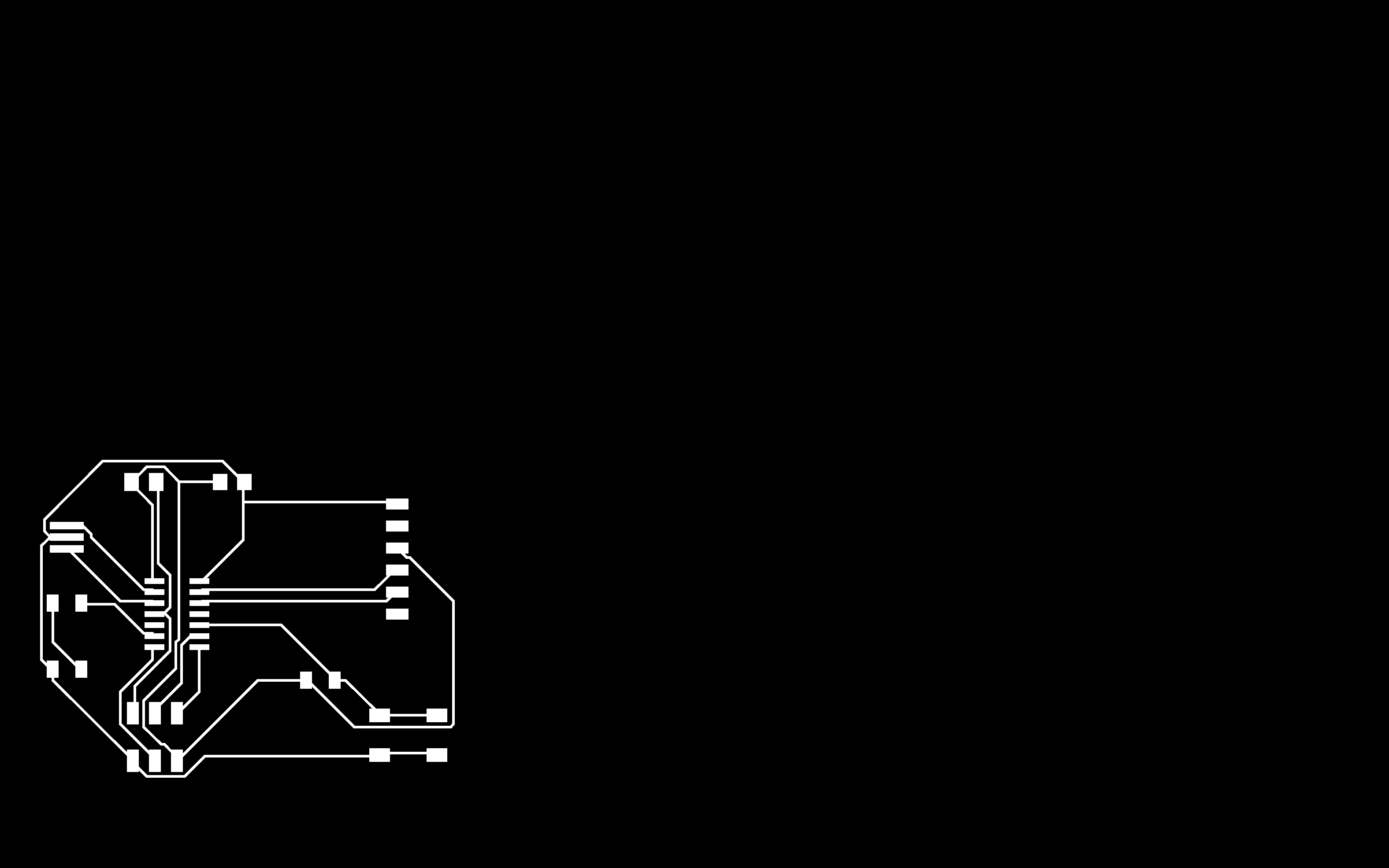
Step 18: This is the png file
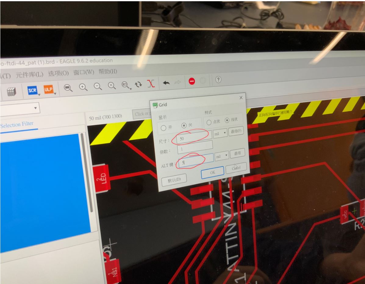
Step 19: By adjusting grid distance to adjust the location of wires.
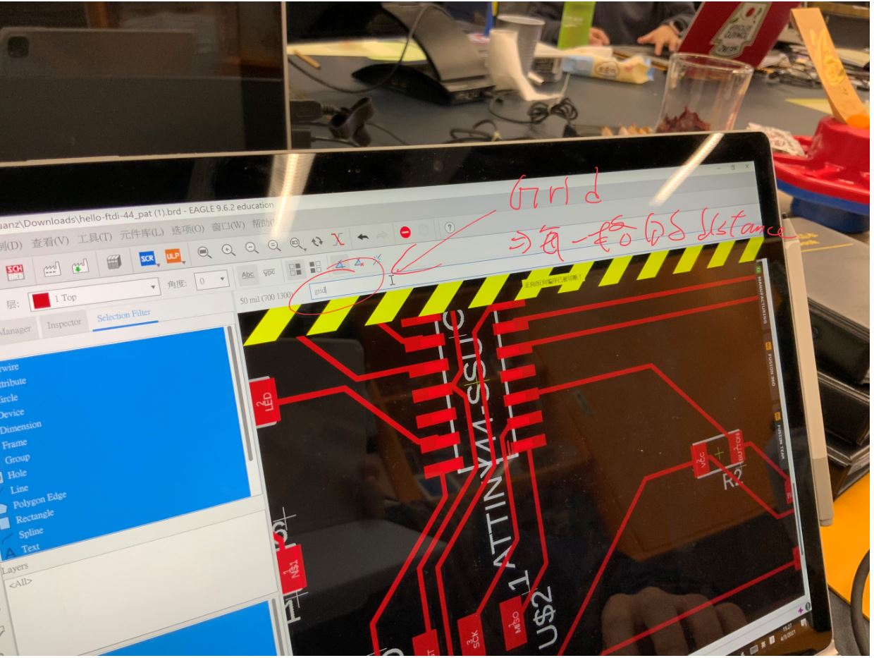
Step 20: Setting ALT button for 5 mil.
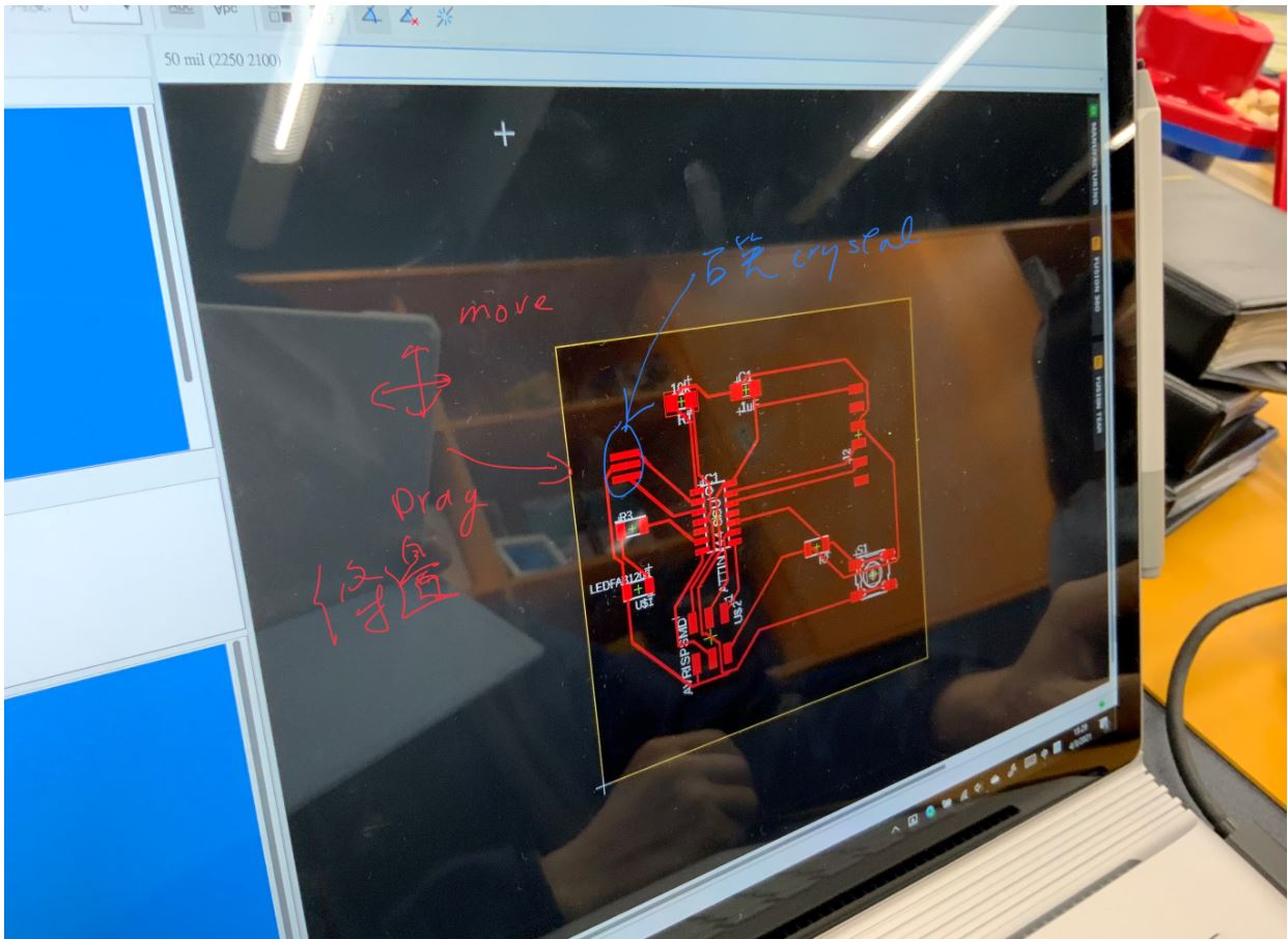
Step 21: Remove the unwanted edge.
Since our lab do not have crystal. The new crystal are still in transportation. Therefore we cant put a crystal on the board right now.
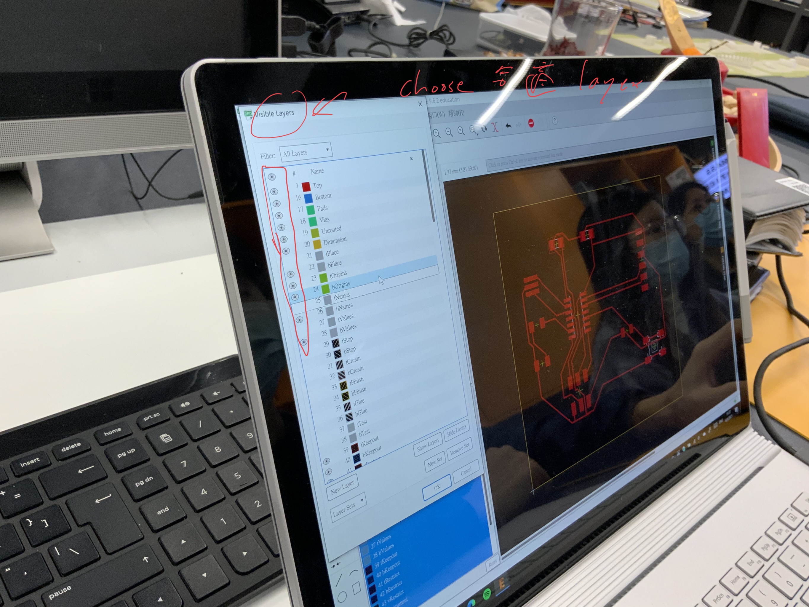
Step 22:
Using a suitable layers.
Step 23:
Also, setting boundary on the board for milling later.

This is the final product.
Please click here to download the schematic file
Please click here to download the board file
Milling
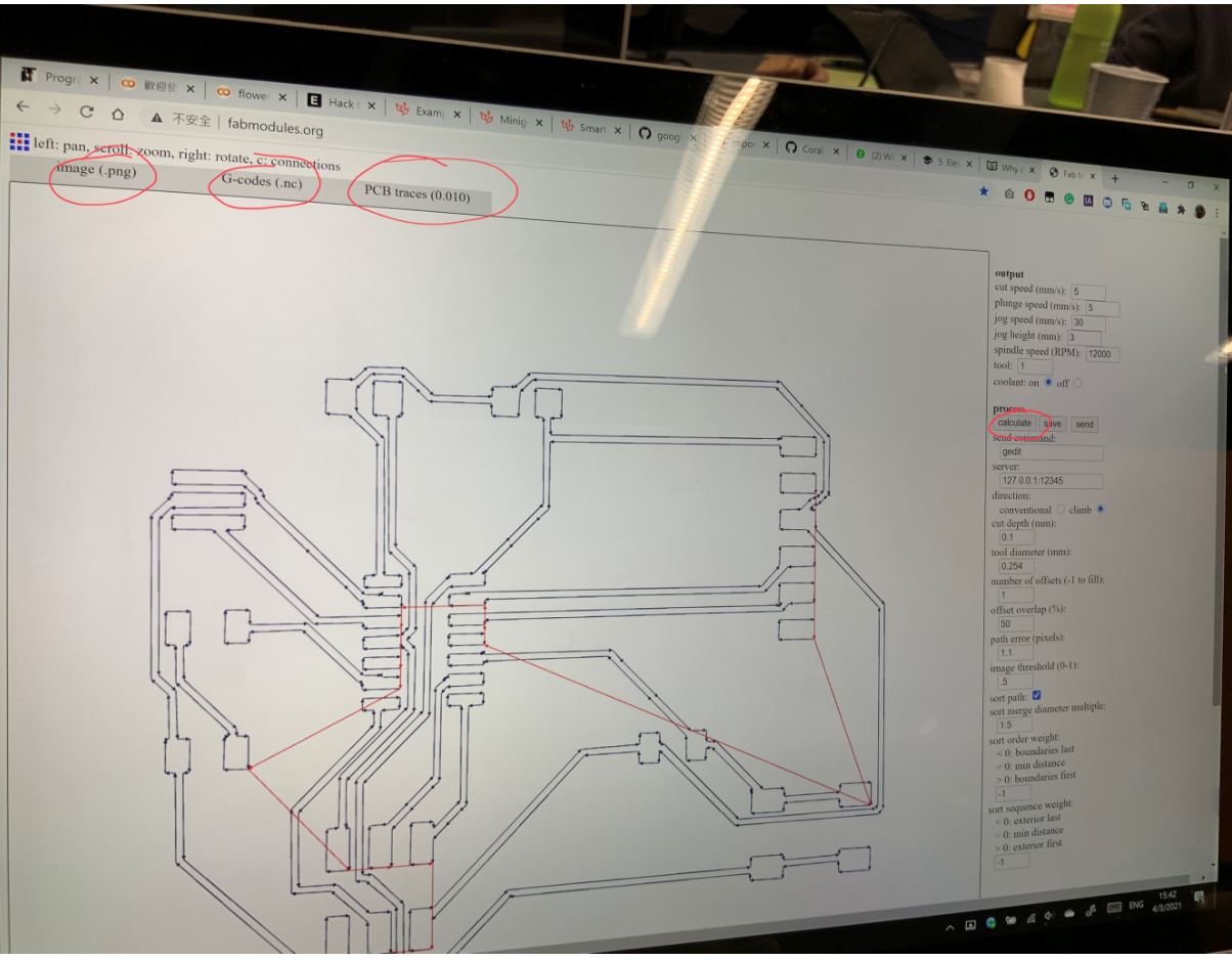
Step 1:
By using fabmodules.org, setting the configuration below for G code calculation.
Step 2:
By using Edytor NC, transfer the G code to CNC.
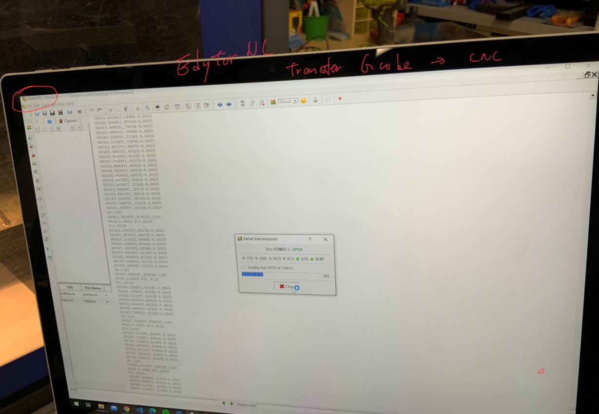
Step 3:
By using Edytor NC, transfer the G code to CNC.
Step 4:
The below video show that milling is operating.
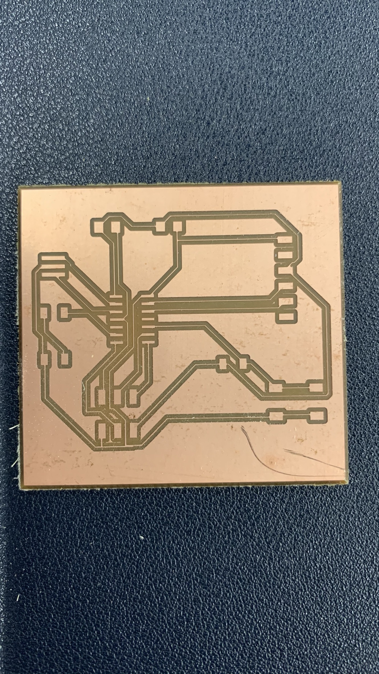
Step 5:
After it is finished, the result as below.
Produce the In-Circuit by stuffing the PCB
Step 1:
The milling process is complete.
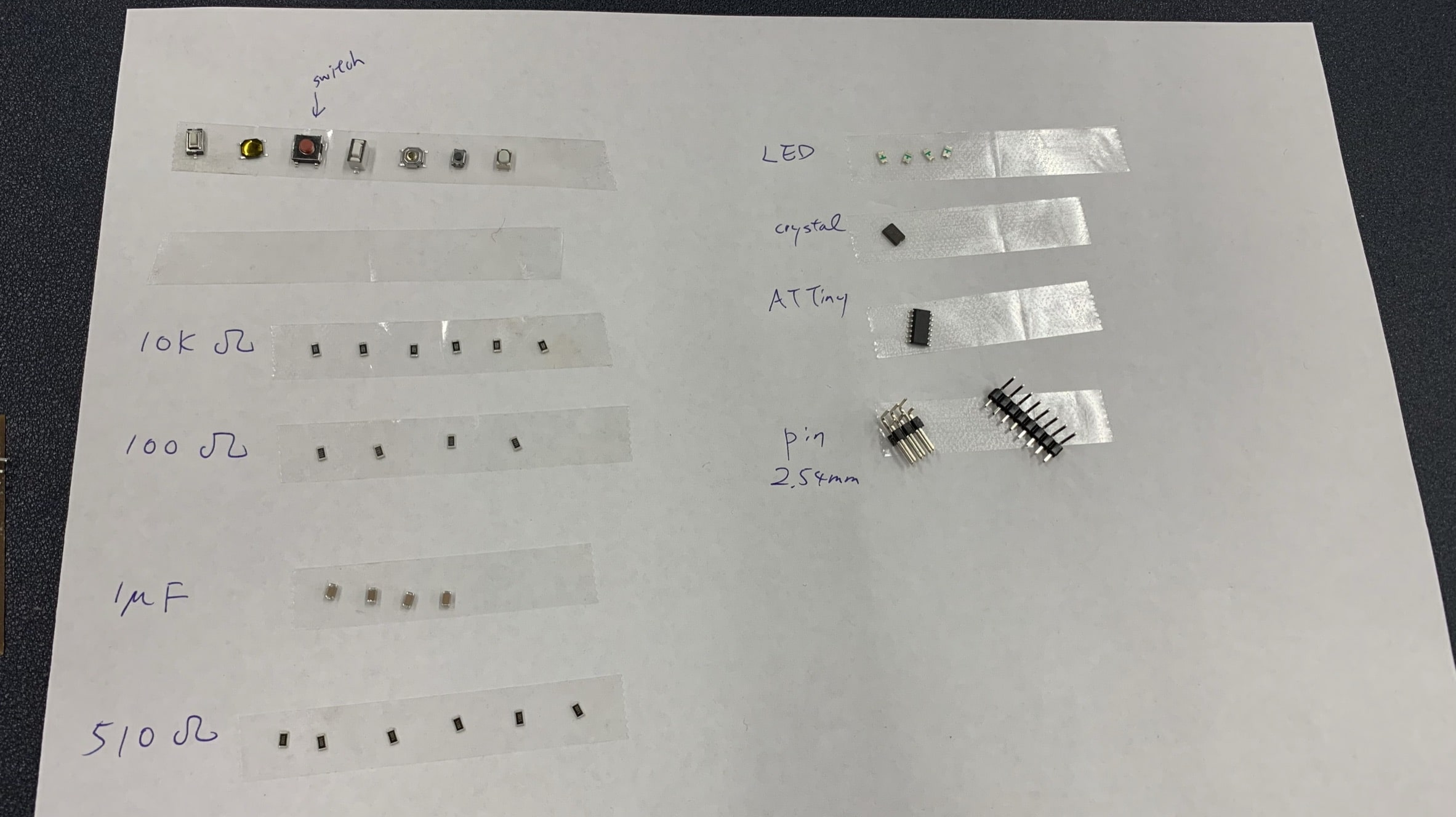
Here is the components are needed for stuffing the PCB.
Step 2:
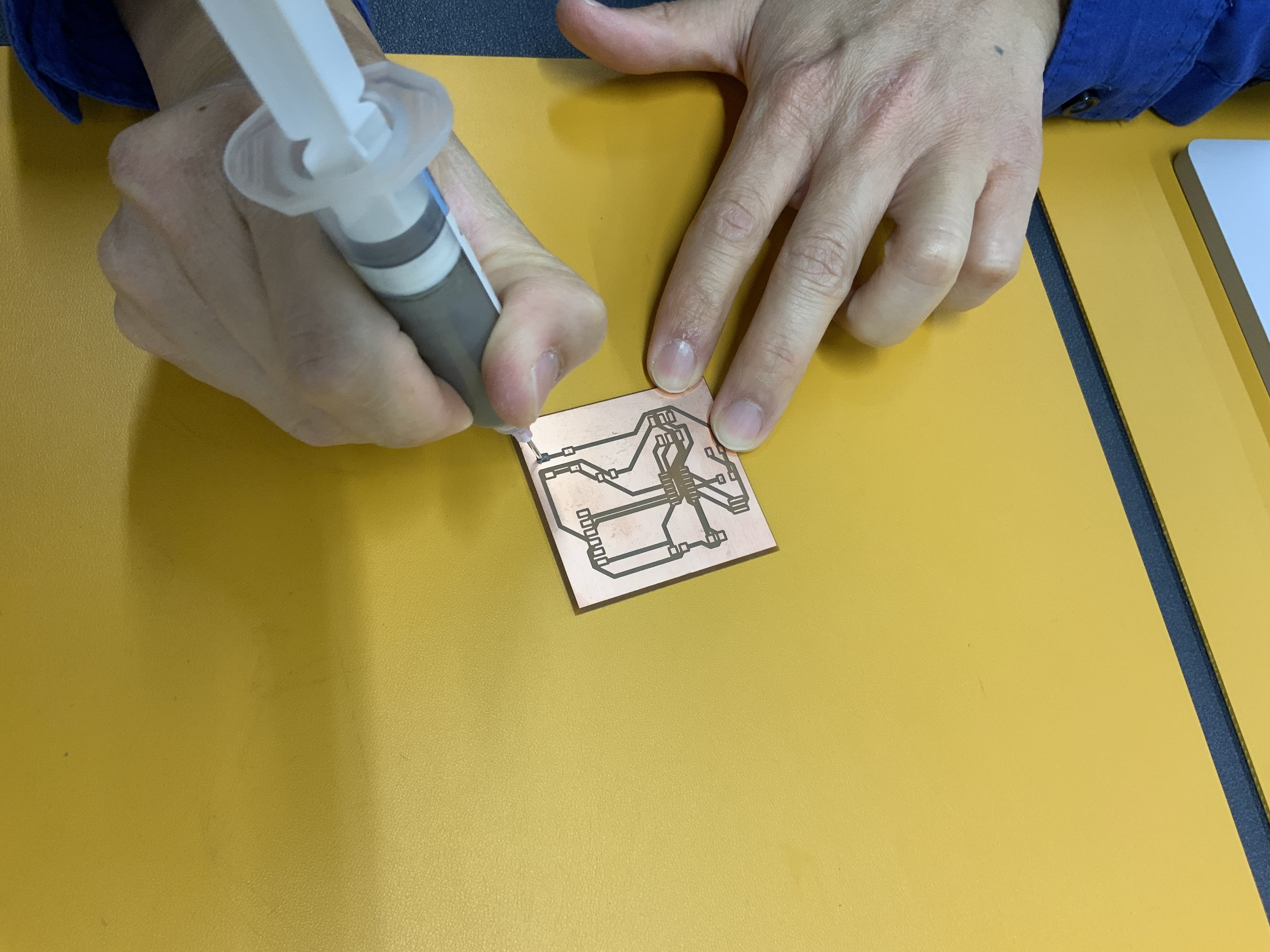
To use lead free solder paste.
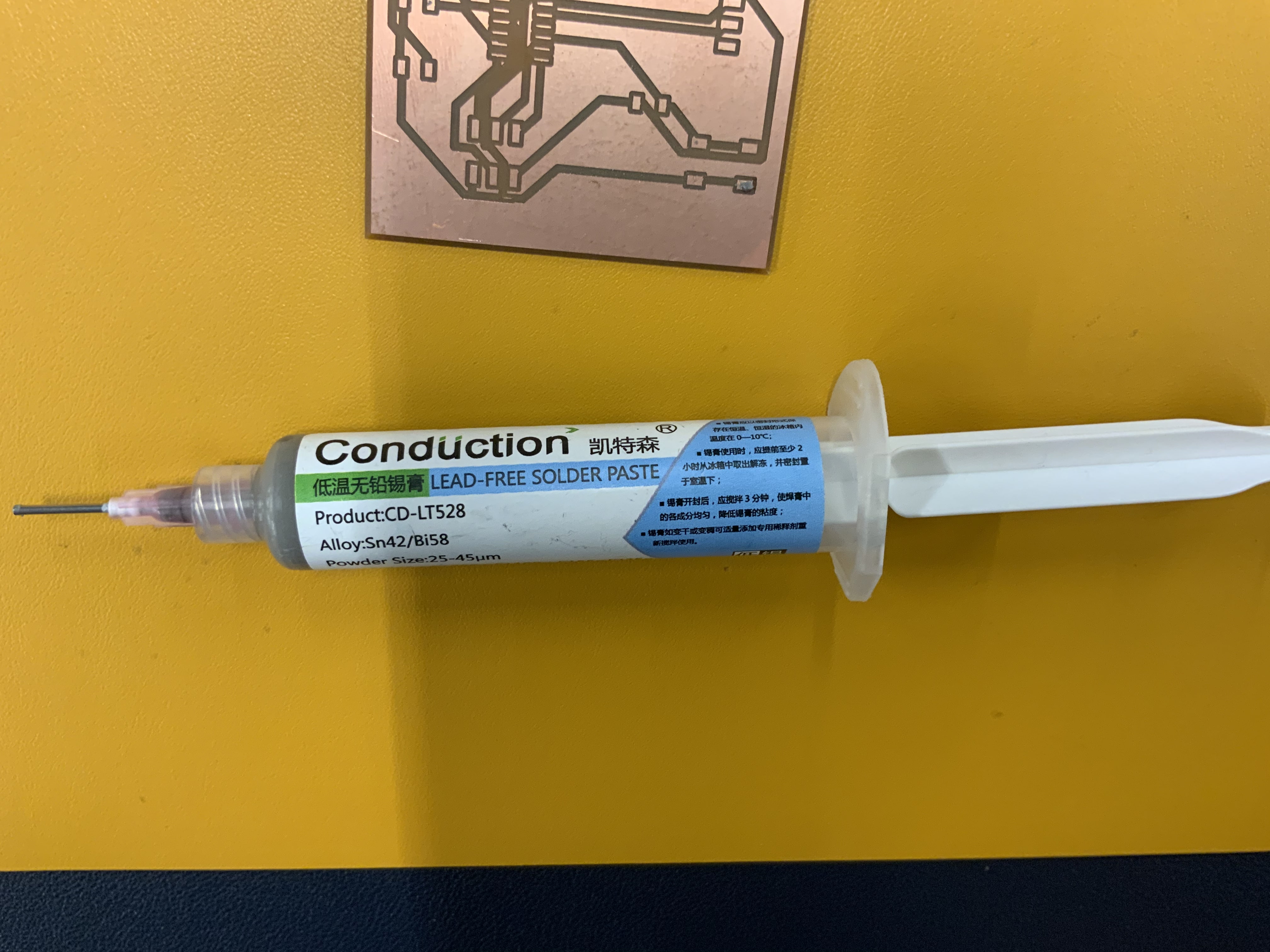
Step 3:
Paste a small amount of “lead free solder paste” into each location.
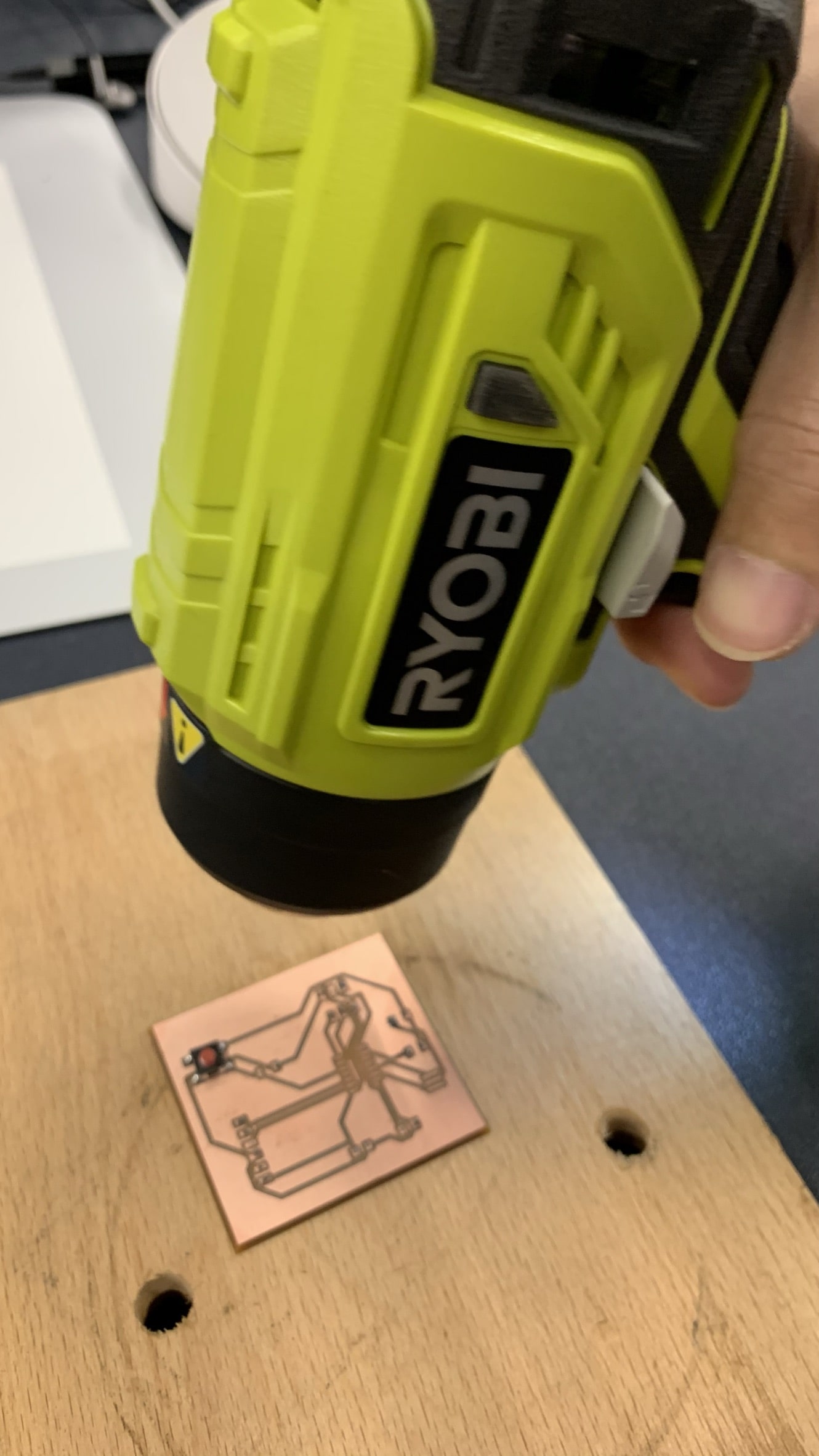
Step 4:
To use a heat gun to warm up the lead free solder paste. Then those paste will be changed to solid states.
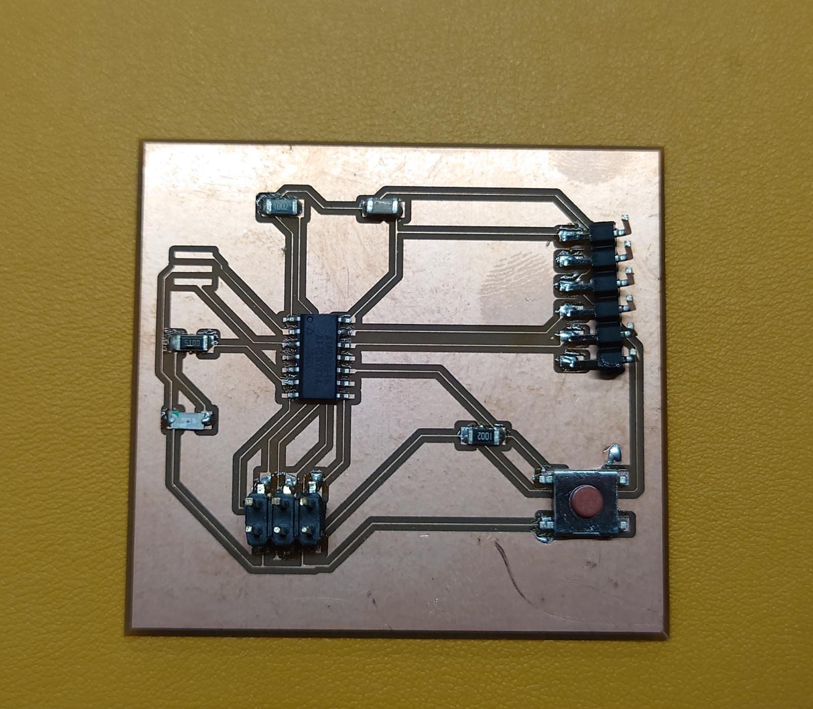
Step 5:
By repeating above steps, the final PCB with components are created.
However, there is no crystal in our labatory. Therefore, we need to wait for the crystal arrived.
Testing
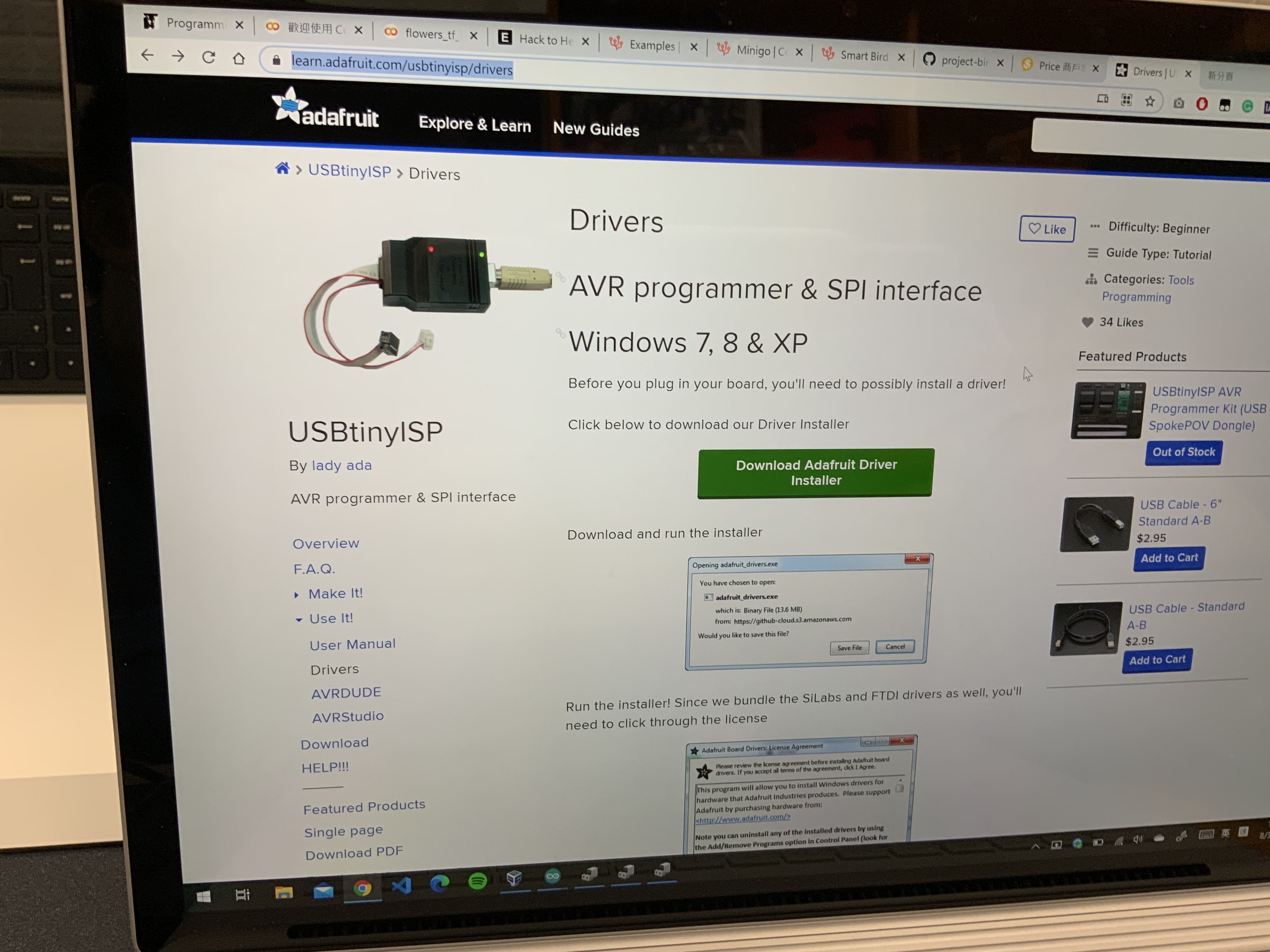
Step 1:
Installing a suitable driver for the AVR programmer & SPI interface.
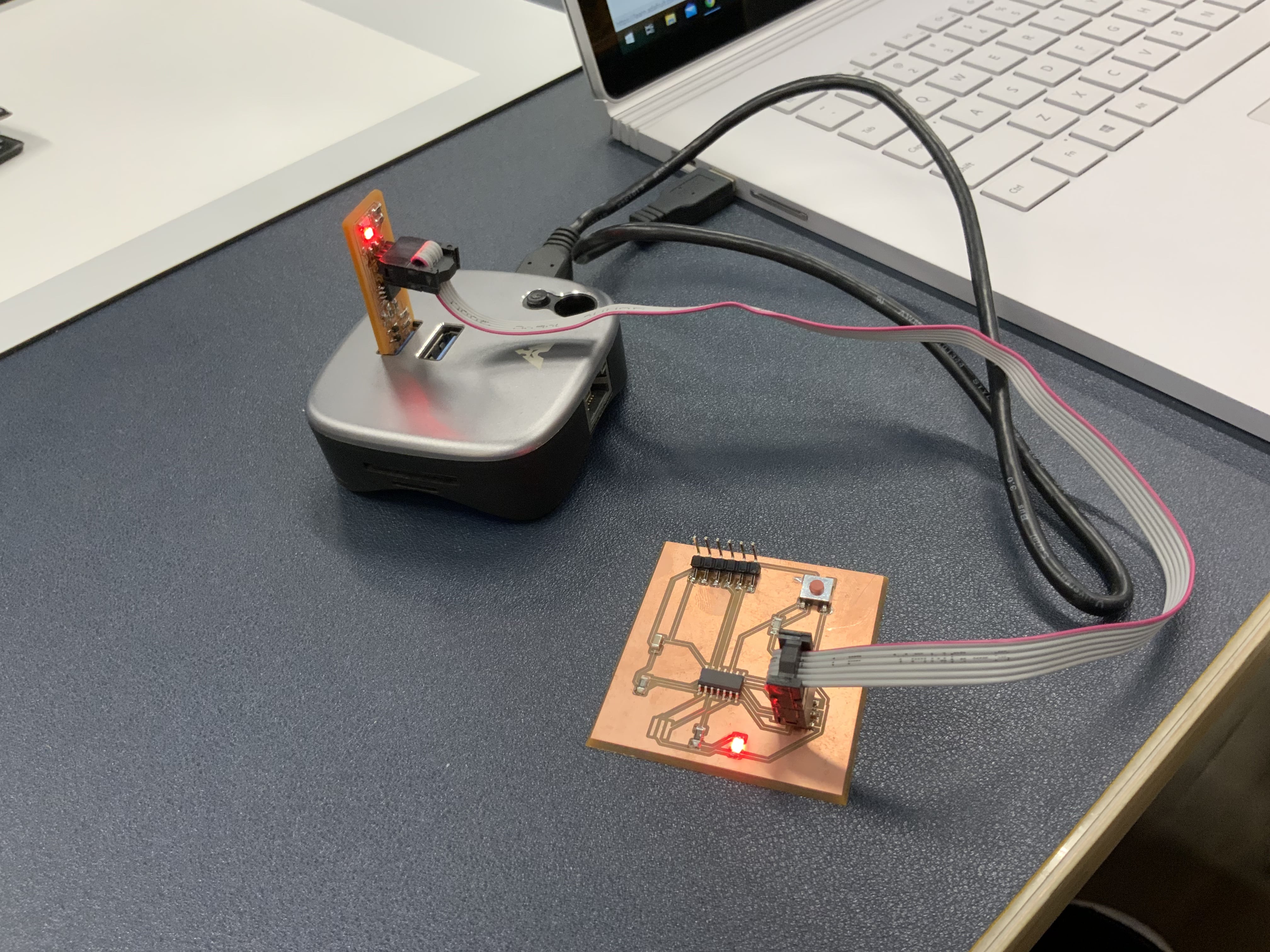
Step 2:
Connecting the PCB together with the ISP and computer.
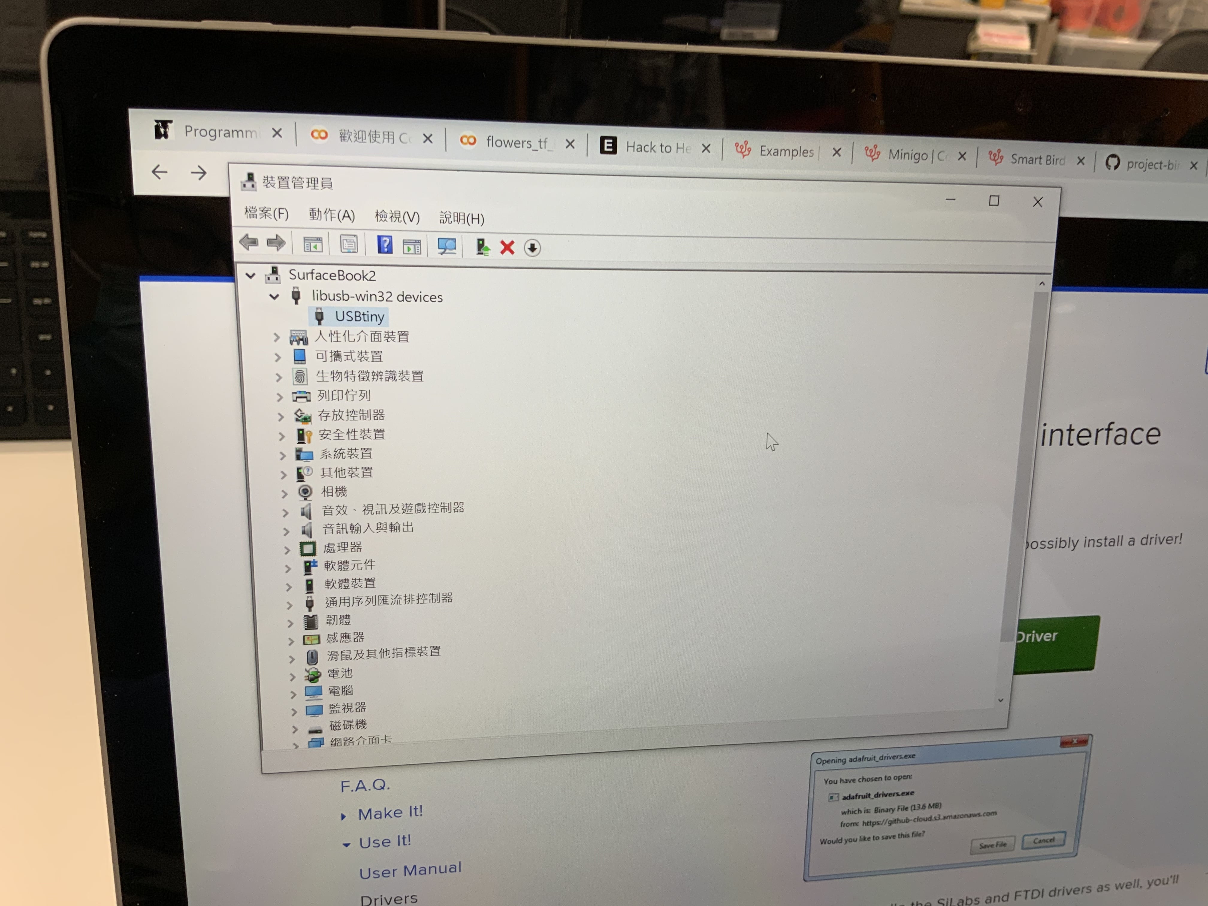
Step 3:
In Windows device management, you found that the USBtiny is connected.
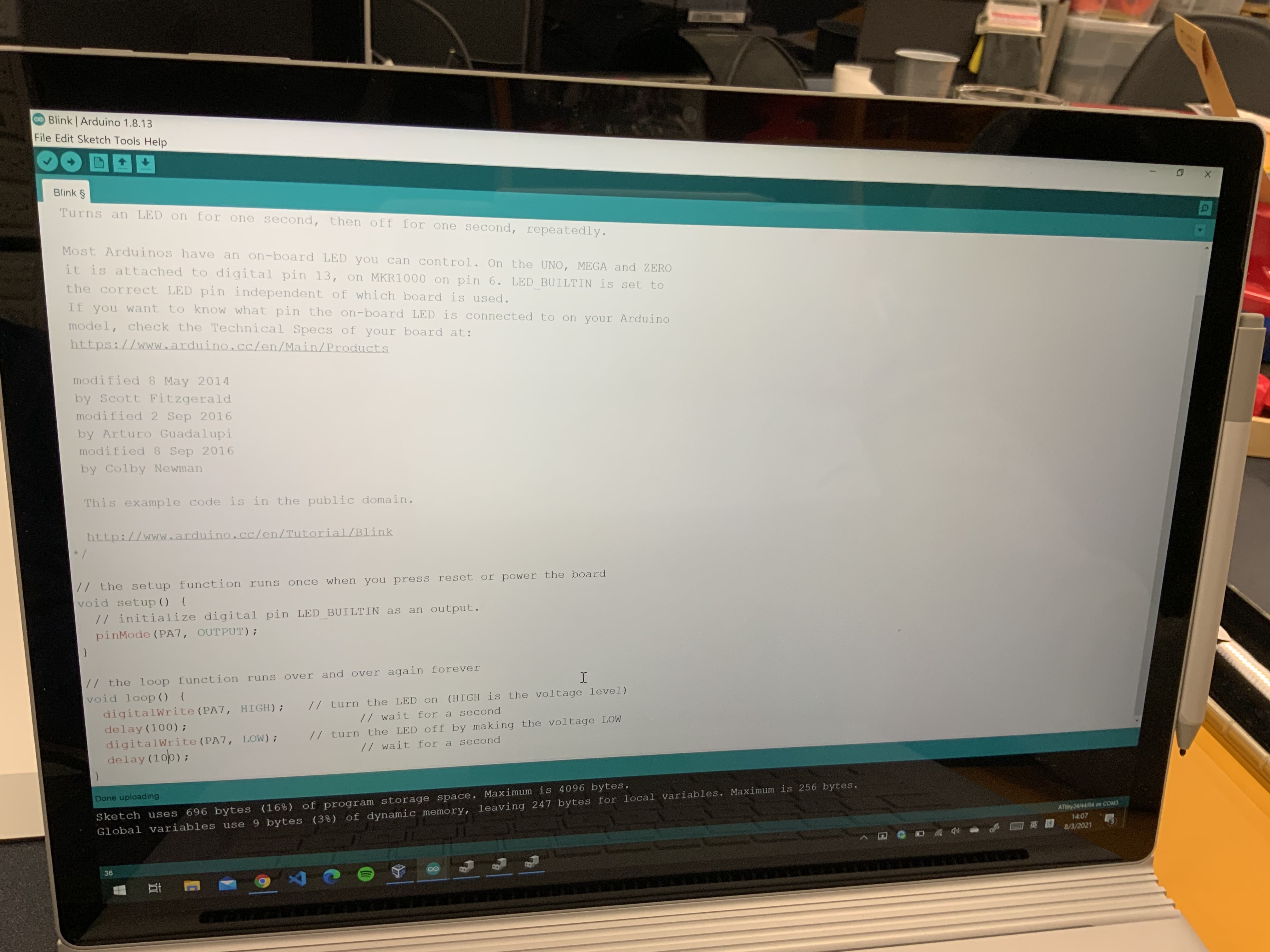
Step 4:
Here is the program for testing.
It is only used to make the LED on and off.
// the setup function runs once when you press reset or power the board
void setup() {
// initialize digital pin LED_BUILTIN as an output.
pinMode(PA7, OUTPUT);
}
// the loop function runs over and over again forever
void loop() {
digitalWrite(PA7, HIGH); // turn the LED on (HIGH is the voltage level)
delay(100); // wait for a second
digitalWrite(PA7, LOW); // turn the LED off by making the voltage LOW
delay(100); // wait for a second
}
Step 5:
The below video show the testing of the PCB.
You find that the LED is keep flashing.
Group assignments
Use the test equipment in your lab to observe the operation of a microcontroller circuit board (in minimum, check operating voltage on the board with multimeter or voltmeter and use oscilloscope to check noise of operating voltage and interpret a data signal) Document your work (in a group or individually)
Here is the link of the group assignment .