11. Input devices
This week task as below:
- Individual project
Measure something: add a sensor to a microcontroller board that you have designed and read it.
I am going to use temperature sensor DS18B20 to measure the room temperature.
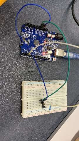
Prototype testing by using beard board
Firstly, I am going to use a bread board for testing the electronic connection for the DS18B20, resistor and the chip. I used a arduino UNO for testing the prototype.
Step 1:
In arduino IDE, I have to use a library manager to include a DS18B20 library.
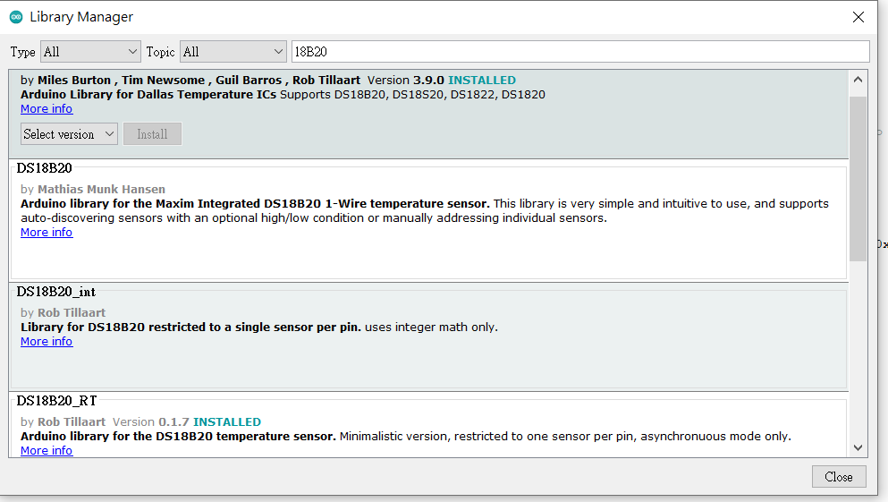
Step 2:
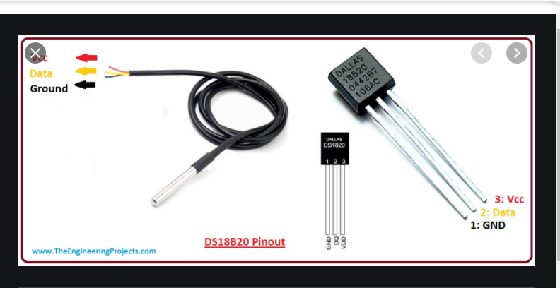
Here is the DS18B20 pinout.
pin 1 is GND, pin 2 is data, pin 3 is Vcc.
Step 3:
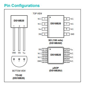
Here is the detailed pin configuration for the DS18B20. The one I used is called TO-92.
Step 4:
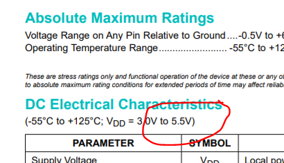
I checked that the VDD for the DS18B20 is from 3.0V to 5.5V.
Therefore I can use 5V for testing.
Step 5:
Here is the prototype testing for the temperature sensor (DS18B20), resistor and the arduino UNO.
Step 6:
Here is the code in the arduino IDE.
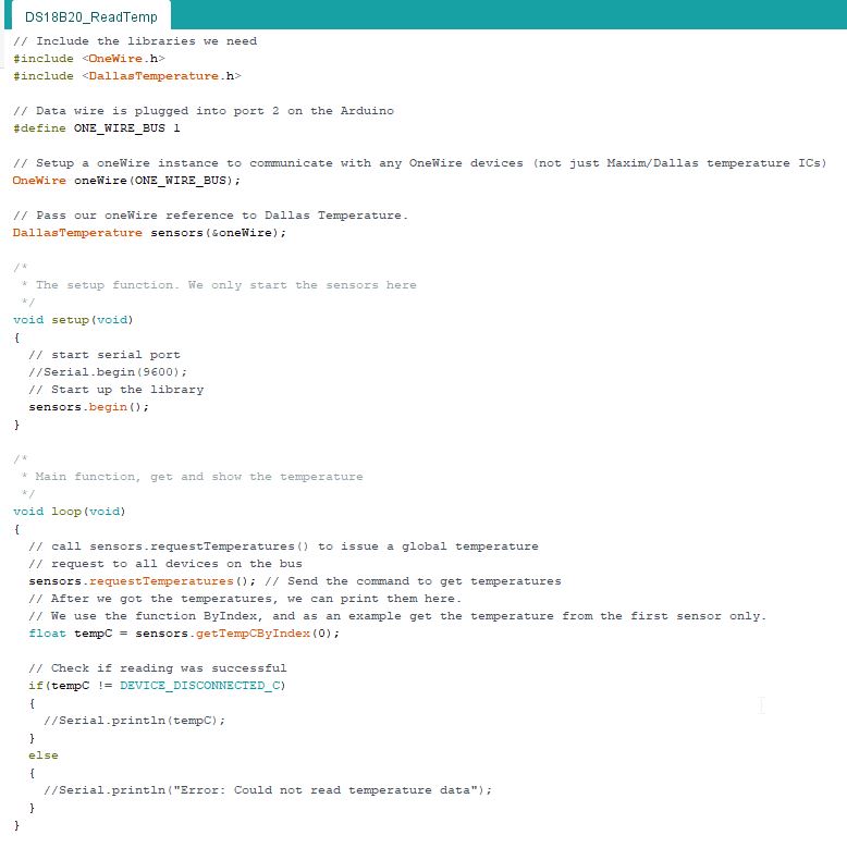
You may also download the program here.
Please click here to download the ino file
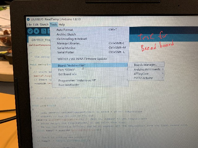
Step 7:
Choosing a suitable board in arduino IDE.
Step 8:
In the following video, you would view the testing. In arduino IDE keep displaying a temperature measured.
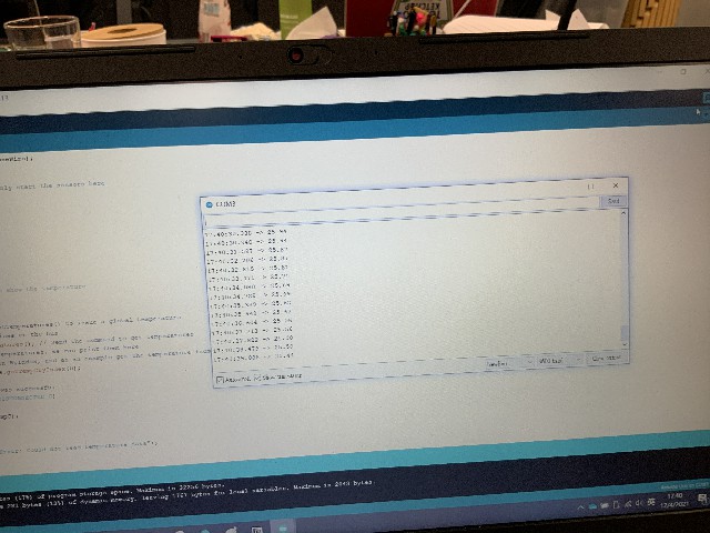
Step 9
This is the testing result. Temperature keep displaying around 25C.
Schematic diagram and board diagram
Step 1:
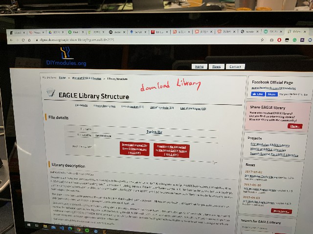
In Eagle, I need to download a suitable library 1wire.lbr
Step 2:
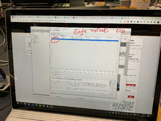
Installing a 1wire library is needed in Library manager.
Step 3:
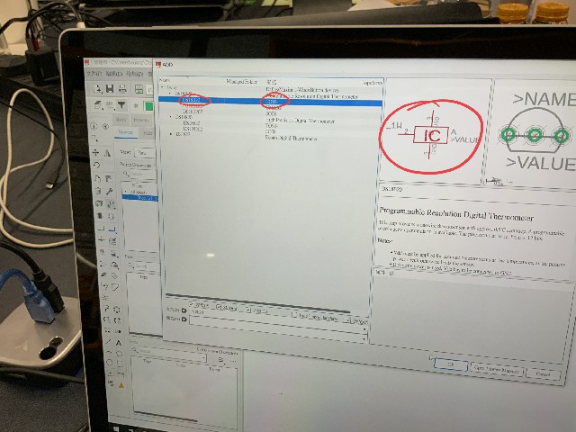
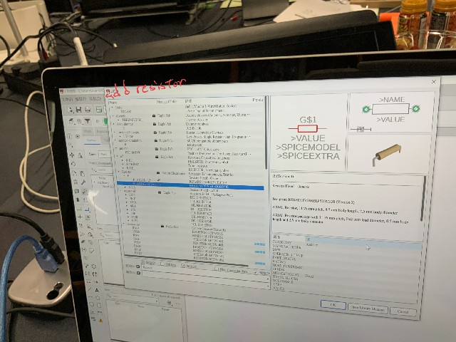
I need to add a temperature sensor - DS18B20 TO92 as shown below.
Step 4:
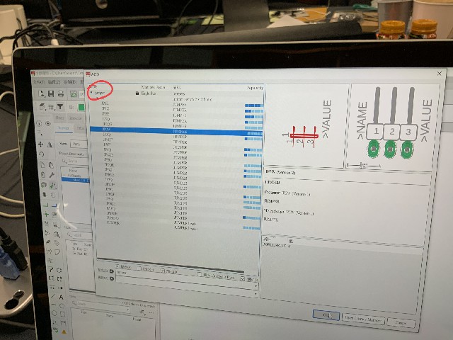
3 pins jumper is needed aslo.
Step 5:
A resistor is also needed.
Step 6:
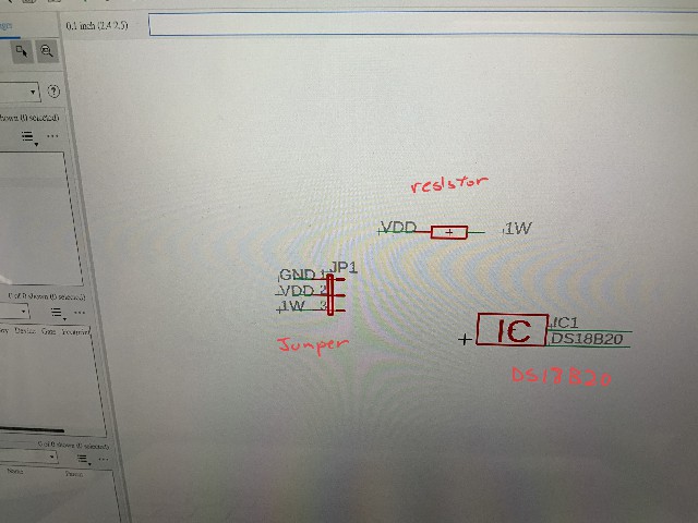
Here is the schematic diagram.
three components are here - DS18B20, resistor and jumper.
Step 7:
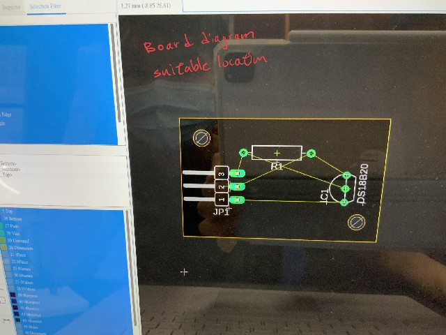
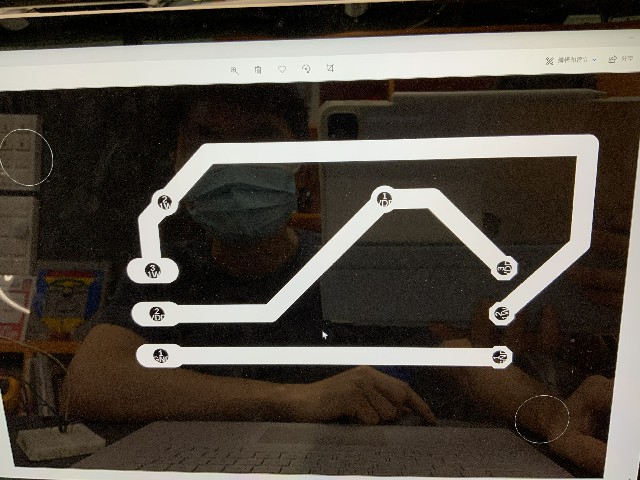
After that I need to draw a board diagram.
Putting the components in a suitable locations.
Step 8:
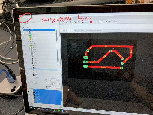
After drawing the electrical wires. Choosing a suitable layers.
Step 9:
Here is the schematic of my board.
It is ready for the next steps.
You may also download the schematic file here.
Please click here to download the sch file
You may also download the board file here.
Please click here to download the brd file
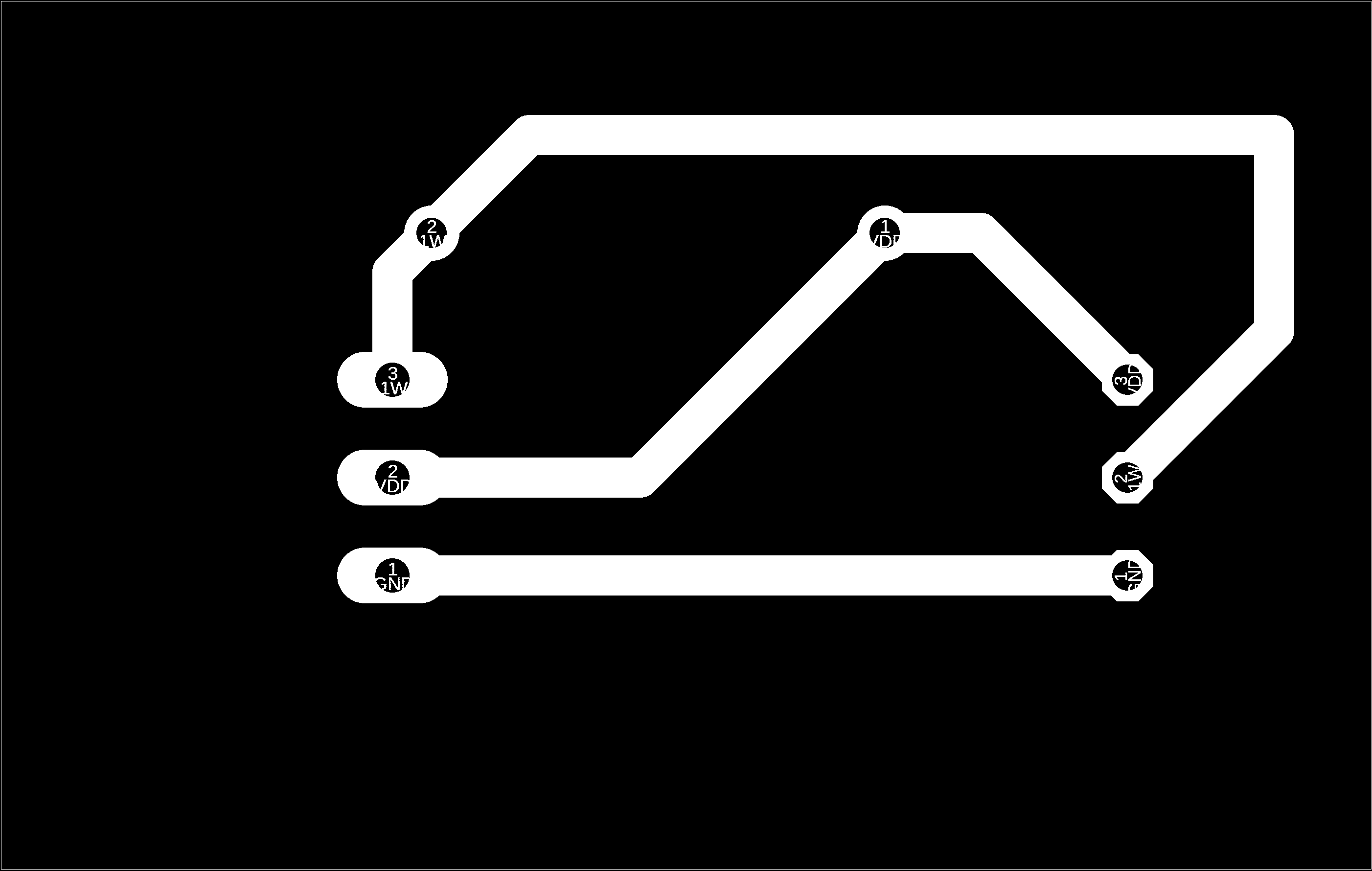
You may also download the trace png file here.
Please click here to download the trace png file
You may also download the outline png file here.
Please click here to download the outline png file
CNC for milling a PCB board
Step 1:
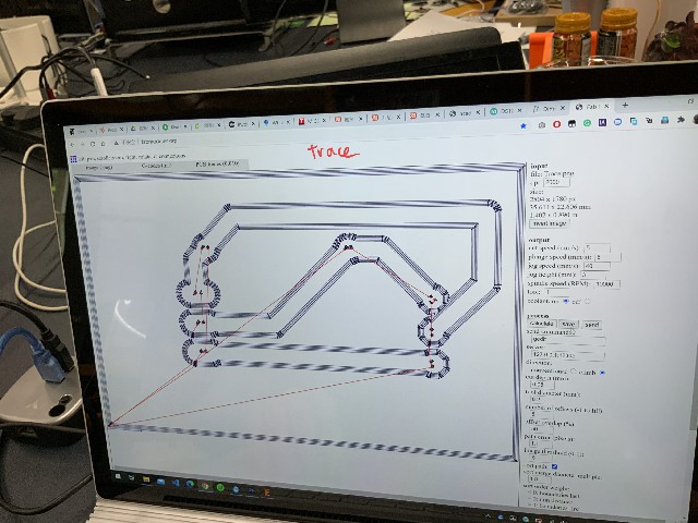
I have to use fabmodules.org to converting the png file into G code
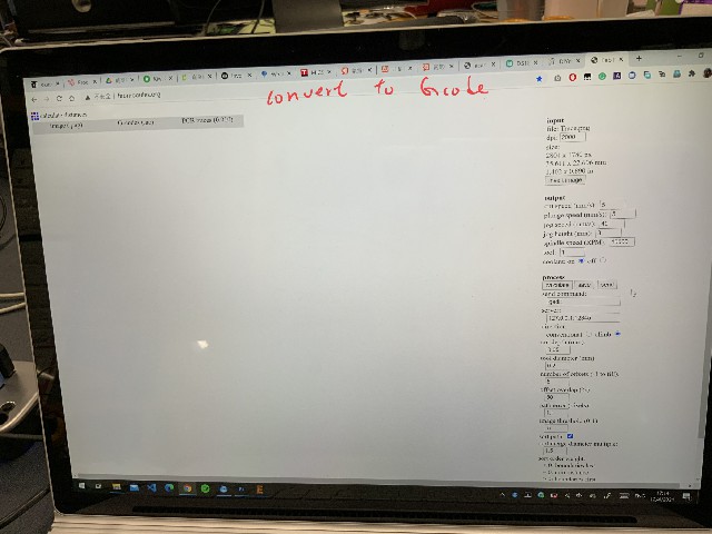
Step 2:
Here is the trace for the CNC knife.
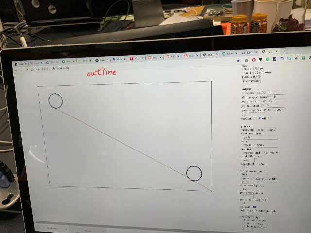
Step 3:
Outline of the PCB board is here.
G code is ready.
You may also download the trace png file here.
Please click here to download the trace nc file
You may also download the outline png file here.
Please click here to download the outline nc file
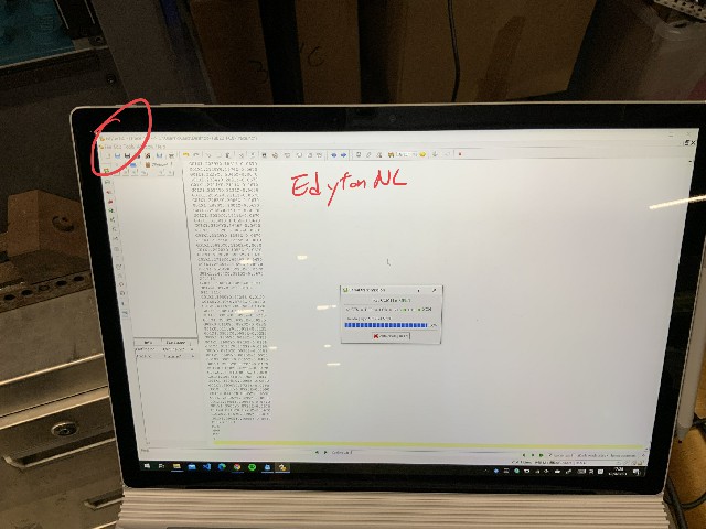
Step 4:
Putting the GCode in Edyton NC for kick start the CNC.
Step 5:
In the following video, you would view the CNC to maufacture the PCB board.
Step 6:
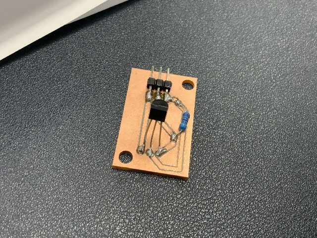
The PCB is completed.
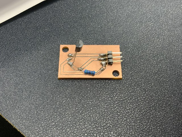
Step 7:
The PCB is completed.
Step 8:
**I forgot to bring my own board from my home to my labatory. Therefore, I need to borrow the board from Lydia Kuo for testing only.
I have borrowed Lydia Kuo PCB for testing my PCB (temperature sensor).
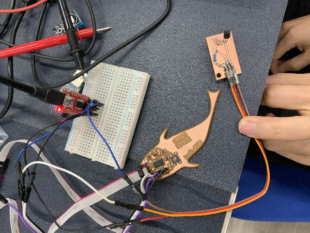
Step 9:
In the following video, you would view the testing result for temperature sensor.
When temperature is lower than 25C, LED will keep flashing.
When temperature is higher than 25C, LED will burn off.
You may also download the program here.
Please click here to download the ino file
Group assignments
Compare the performance and development workflows for different microcontroller families
Document your work (in a group or individually)
Here is the link of the group assignment .