12. Output devices
in this week I work for the final project to make the screen as output form my device
Group Assignment
output circuit
servo motor
Servo motors have been around for a long time and are utilized in many applications. They are small in size but pack a big punch and are very energy-efficient. These features allow them to be used to operate remote-controlled or radio-controlled toy cars, robots and airplanes.
Types of Servo Motors
There are two types of servo motors - AC and DC. AC servo can handle higher current surges and tend to be used in industrial machinery. DC servos are not designed for high current surges and are usually better suited for smaller applications. Generally speaking, DC motors are less expensive than their AC counterparts. These are also servo motors that have been built specifically for continuous rotation, making it an easy way to get your robot moving. They feature two ball bearings on the output shaft for reduced friction and easy access to the rest-point adjustment potentiometer.
Servo Motor Applications
Servos are used in radio-controlled airplanes to position control surfaces like elevators, rudders, walking a robot, or operating grippers. Servo motors are small, have built-in control circuitry and have good power for their size.
you can find more about servo motor here
design
for more information in how to make circuit you can find it in the how to start electronics design here , for this time I used different program but it is smaller to EAGLE and it easy to get used to it, it called EasyEDA here
components:
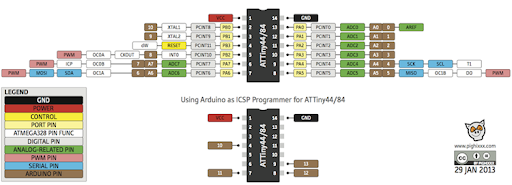
ATtiny84
led X2
resistor X3
capacitor
pin headers
jumper

these are the other component for the circuit

then I start making connection between


next I added thing together


then I starting making the board


milling


soldering

Coding
/*
  Fade

  This example shows how to fade an LED on pin 9 using the analogWrite()
  function.

  The analogWrite() function uses PWM, so if you want to change the pin you're
  using, be sure to use another PWM capable pin. On most Arduino, the PWM pins
  are identified with a "~" sign, like ~3, ~5, ~6, ~9, ~10 and ~11.

  This example code is in the public domain.

  http://www.arduino.cc/en/Tutorial/Fade
*/

int led = PA5;           // the PWM pin the LED is attached to
int brightness = 0;    // how bright the LED is
int fadeAmount = 5;    // how many points to fade the LED by

// the setup routine runs once when you press reset:
void setup() {
  // declare pin 9 to be an output:
  pinMode(led, OUTPUT);
}

// the loop routine runs over and over again forever:
void loop() {
  // set the brightness of pin 9:
  analogWrite(led, brightness);

  // change the brightness for next time through the loop:
  brightness = brightness + fadeAmount;

  // reverse the direction of the fading at the ends of the fade:
  if (brightness <= 0 || brightness >= 255) {
    fadeAmount = -fadeAmount;
  }
  // wait for 30 milliseconds to see the dimming effect
  delay(30);
}
Files
final project circuit
as you see in the video the screen work, this is what I used for the final project.

I used three PCB as one circuit and I call it the sandwich circuit because it three PCB that are contacted to each other
screen
I used a screen as an output “OLED 0.96”
since the OLED display uses I2C communication protocol, wiring is very simple.

I2C communication

it is one of the most communication ways used , I2C, is a half-duplex hardware protocol that uses two conductors, one clock (SCL) and one data (SDA) line, to connect two or more devices. One device, designated the master, uses the clock signal to synchronize data transfer to one, or multiple, slave devices at speeds up to 400 Kbps.
circuit
the problem that I faced was I need to put a lot of thing in small pace so what I did is making three circuit in top of each other, this solution help me a lot.
Components:
ATtiny84
Resistor:
10k rest
1k “for the Bluetooth”
2k “for the Bluetooth”
capacitor:
1uf
Pin out 4X1–2 3X2 3X1 6X1
Wire jumper X3
Bluetooth ht05
Connection
base circuit


Bluetooth circuit**


Code
What it will do ?
first it will get data from the other device by the Bluetooth and the screen will show dingers sign on the right or lift deplaned on the date that it received .
How it will do it ?
there is three are number that this devise will received “0” and it mean nothing happen and reset the screen , “1” the lift sensor detect something close to you from the lift side. and “2” the right sensor detect something close to you from the right side.
void loop() {
  int x = 0 ;
 if(mySerial.available() > 0){
    x = mySerial.read();
 }

 if (x == '1')
 {
  oled.begin();
  oled.clear();
  oled.bitmap(0,0, 128,4, lift1);
  oled.on();
  delay(250);

  oled.begin();
  oled.clear();
  oled.bitmap(0,0, 128,4, lift2);
  oled.on();
  delay(250);

  oled.begin();
  oled.clear();
  oled.bitmap(0,0, 128,4, lift3);
  oled.on();
  delay(250);
 }

  if (x == '2')
  {
  oled.begin();
  oled.clear();
  oled.bitmap(0,0, 128,4, right1);
  oled.on();
  delay(250);


  oled.begin();
  oled.clear();
  oled.bitmap(0,0, 128,4, right2);
  oled.on();
  delay(250);

  oled.begin();
  oled.clear();
  oled.bitmap(0,0, 128,4, right3);
  oled.on();
  delay(250);
  }
  else {
  oled.begin();
  oled.clear();

  }
  }
and the idea of the three images in loop is to make an arrow to move.
main code
// the setup function runs once when you press reset or power the board
void setup() {
  // initialize digital pin LED_BUILTIN as an output.
  pinMode(LED_BUILTIN, OUTPUT);
}

// the loop function runs over and over again forever
void loop() {
  digitalWrite(LED_BUILTIN, HIGH);   // turn the LED on (HIGH is the voltage level)
  delay(1000);                       // wait for a second
  digitalWrite(LED_BUILTIN, LOW);    // turn the LED off by making the voltage LOW
  delay(1000);                       // wait for a second
}#include <Tiny4kOLED.h>
#include "SolomonSystech.h"
#include <SoftwareSerial.h>
SoftwareSerial mySerial(1,6); // RX1, TX6
// ============================================================================

void setup() {


  oled.begin();
  oled.clear();
  oled.bitmap(0,0, 128,4, logo);
  oled.on();
  delay(1000);
  oled.clear();

 mySerial.begin(9600);
}

void loop() {
  int x = 0 ;
 if(mySerial.available() > 0){
    x = mySerial.read();
 }

 if (x == '1')
 {
  oled.begin();
  oled.clear();
  oled.bitmap(0,0, 128,4, lift1);
  oled.on();
  delay(250);

  oled.begin();
  oled.clear();
  oled.bitmap(0,0, 128,4, lift2);
  oled.on();
  delay(250);

  oled.begin();
  oled.clear();
  oled.bitmap(0,0, 128,4, lift3);
  oled.on();
  delay(250);
 }

  if (x == '2')
  {
  oled.begin();
  oled.clear();
  oled.bitmap(0,0, 128,4, right1);
  oled.on();
  delay(250);


  oled.begin();
  oled.clear();
  oled.bitmap(0,0, 128,4, right2);
  oled.on();
  delay(250);

  oled.begin();
  oled.clear();
  oled.bitmap(0,0, 128,4, right3);
  oled.on();
  delay(250);
  }
  else {
  oled.begin();
  oled.clear();

  }
  }
photo convector
this web convert the image to code then the so the read the code and convert it to image into the screen.
const uint8_t logo [] PROGMEM = {
  0x00, 0x00, 0x00, 0x00, 0x00, 0x00, 0x00, 0x00, 0x00, 0x00, 0x00, 0x00, 0x00, 0x00, 0x00, 0x00,
  0x00, 0x00, 0x00, 0x00, 0x00, 0x00, 0x00, 0x00, 0x00, 0x00, 0x00, 0x00, 0x00, 0x00, 0x00, 0x00,
  0x00, 0x00, 0x00, 0x00, 0x00, 0x38, 0x00, 0x00, 0x20, 0x18, 0x18, 0x10, 0x00, 0x38, 0x00, 0x08,
  0x18, 0x10, 0x20, 0x00, 0x00, 0x30, 0x18, 0x18, 0x30, 0x00, 0x38, 0x00, 0x38, 0x00, 0x00, 0x00,
  0x38, 0x00, 0x00, 0x38, 0x00, 0x10, 0x18, 0x18, 0x20, 0x38, 0x00, 0x00, 0x18, 0x00, 0x38, 0x10,
  0x10, 0x28, 0x20, 0x18, 0x18, 0x18, 0x20, 0x00, 0x38, 0x00, 0x38, 0x08, 0x10, 0x38, 0x00, 0x00,
  0x00, 0x00, 0x00, 0x00, 0x00, 0x00, 0x00, 0x00, 0x00, 0x00, 0x00, 0x00, 0x00, 0x00, 0x00, 0x00,
  0x00, 0x00, 0x00, 0x00, 0x00, 0x00, 0x00, 0x00, 0x00, 0x00, 0x00, 0x00, 0x00, 0x00, 0x00, 0x00,
  0x00, 0x00, 0x00, 0x00, 0x00, 0x00, 0x00, 0x00, 0x00, 0x00, 0x00, 0x00, 0x00, 0x00, 0x00, 0x00,
  0x00, 0x00, 0x00, 0x00, 0x00, 0x00, 0x00, 0x00, 0x00, 0x00, 0x00, 0x00, 0x00, 0x00, 0x00, 0x00,
  0x00, 0x00, 0x00, 0x00, 0x00, 0x00, 0x00, 0x00, 0x00, 0x00, 0x00, 0x00, 0x00, 0x00, 0x00, 0x00,
  0x00, 0x00, 0x00, 0x00, 0x00, 0x00, 0x00, 0x00, 0x00, 0x00, 0x00, 0x00, 0x00, 0x00, 0x00, 0x00,
  0x00, 0x00, 0x00, 0x00, 0x00, 0x00, 0x00, 0x00, 0x00, 0x00, 0x00, 0x00, 0x00, 0x00, 0x00, 0x00,
  0x00, 0x00, 0x00, 0x00, 0x00, 0x00, 0x00, 0x00, 0x00, 0x00, 0x00, 0x00, 0x00, 0x00, 0x00, 0x00,
  0x00, 0x00, 0x00, 0x00, 0x00, 0x00, 0x00, 0x00, 0x00, 0x00, 0x00, 0x00, 0x00, 0x00, 0x00, 0x00,
  0x00, 0x00, 0x00, 0x00, 0x00, 0x00, 0x00, 0x00, 0x00, 0x00, 0x00, 0x00, 0x00, 0x00, 0x00, 0x00,
  0x00, 0x00, 0x00, 0x00, 0x00, 0x00, 0x00, 0x00, 0x00, 0x00, 0x00, 0x00, 0x00, 0xfe, 0xfe, 0xc0,
  0xe0, 0xf0, 0xb0, 0x18, 0x0c, 0x06, 0x02, 0x00, 0x00, 0xf8, 0xfc, 0x0c, 0x06, 0x06, 0x02, 0x02,
  0x06, 0x06, 0x0c, 0xfc, 0xf0, 0x00, 0x00, 0xe0, 0xf8, 0x1c, 0x04, 0x06, 0x02, 0x02, 0x02, 0x06,
  0x06, 0x1c, 0xf8, 0xf0, 0x00, 0x00, 0x00, 0xfe, 0xfc, 0x40, 0x40, 0x40, 0x40, 0x40, 0x40, 0xfe,
  0xfe, 0x00, 0x00, 0x00, 0x00, 0xfe, 0xfe, 0x46, 0x46, 0x46, 0x46, 0x46, 0x46, 0x42, 0x00, 0x00,
  0x00, 0x06, 0x06, 0x06, 0xfe, 0xfc, 0x00, 0x00, 0x02, 0x06, 0xfe, 0xfe, 0x06, 0x02, 0x00, 0x00,
  0x78, 0xfc, 0xc6, 0x86, 0x82, 0x82, 0x86, 0xdc, 0xf8, 0x60, 0x00, 0x10, 0x7c, 0xfc, 0x86, 0x82,
  0x82, 0x86, 0x86, 0xfc, 0xf8, 0x00, 0x00, 0x00, 0x00, 0x00, 0x00, 0x00, 0x00, 0x00, 0x00, 0x00,
  0x00, 0x00, 0x00, 0x00, 0x00, 0x00, 0x00, 0x00, 0x00, 0x00, 0x00, 0x00, 0x00, 0x1f, 0x0f, 0x00,
  0x00, 0x01, 0x03, 0x07, 0x0e, 0x0c, 0x18, 0x00, 0x00, 0x03, 0x07, 0x0c, 0x08, 0x18, 0x18, 0x18,
  0x18, 0x08, 0x0c, 0x07, 0x03, 0x00, 0x00, 0x01, 0x07, 0x0f, 0x0c, 0x18, 0x18, 0x18, 0x18, 0x18,
  0x0c, 0x0e, 0x07, 0x01, 0x00, 0x00, 0x00, 0x1f, 0x0f, 0x00, 0x00, 0x00, 0x00, 0x00, 0x00, 0x0f,
  0x1f, 0x00, 0x00, 0x00, 0x00, 0x1f, 0x1f, 0x18, 0x18, 0x18, 0x18, 0x18, 0x18, 0x08, 0x00, 0x18,
  0x18, 0x18, 0x18, 0x0c, 0x0f, 0x03, 0x00, 0x00, 0x08, 0x18, 0x1f, 0x1f, 0x18, 0x08, 0x00, 0x00,
  0x00, 0x18, 0x18, 0x18, 0x19, 0x08, 0x0c, 0x07, 0x03, 0x00, 0x00, 0x00, 0x00, 0x18, 0x18, 0x19,
  0x19, 0x08, 0x0c, 0x07, 0x03, 0x00, 0x00, 0x00, 0x00, 0x00, 0x00, 0x00, 0x00, 0x00, 0x00, 0x00
};
Files
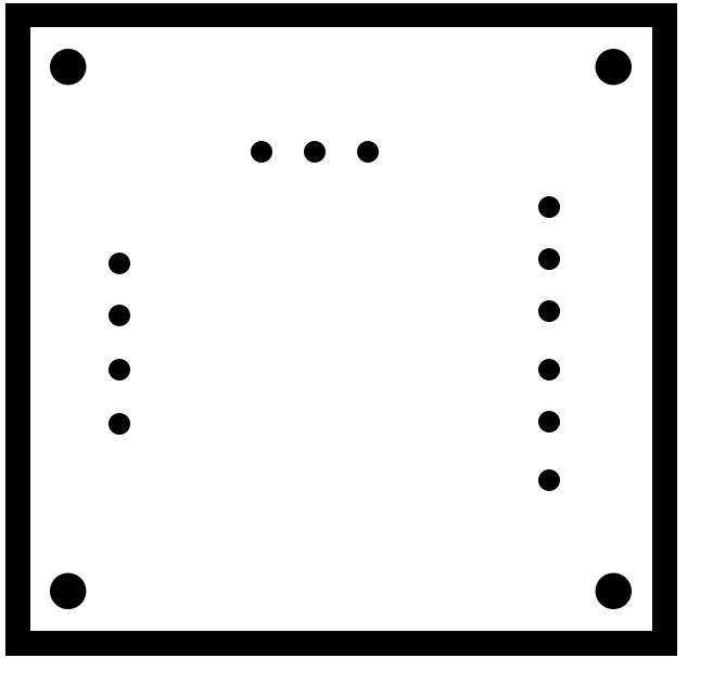
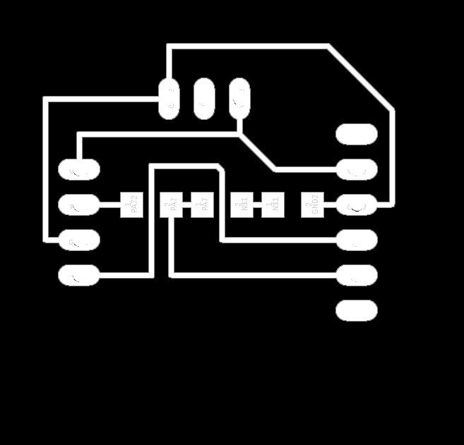
PCB1
traces :
outline :
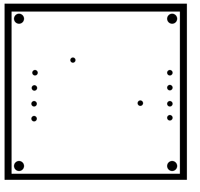
PCB2
outline :