9. Embedded programming
Group Assignment
programming using Arduino UNO
I did this during the lockdown and I didn’t finish my programmer so I used Arduino
I learned how to programmer my circuit from the Arduino as programmer from this here
and from my understanding I did these steps
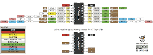
first you should download the Arduino IDE and the ATtiny library
to start programming my board I must make the Arduino UNO as programmer to do this there are few steps :
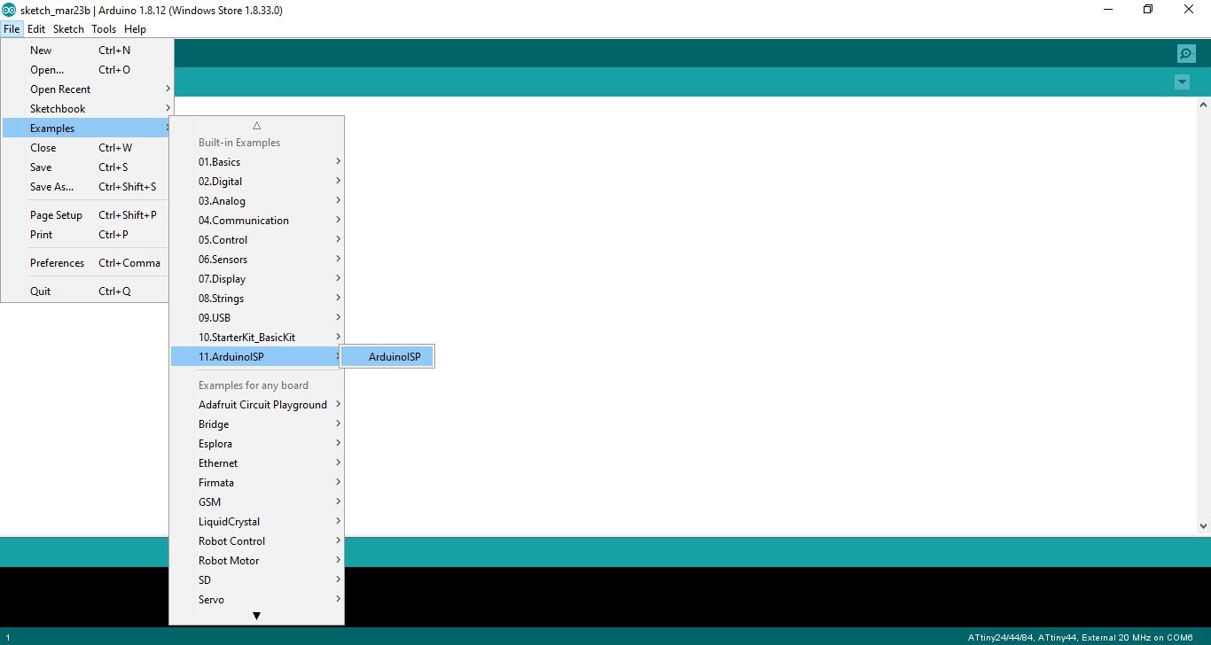
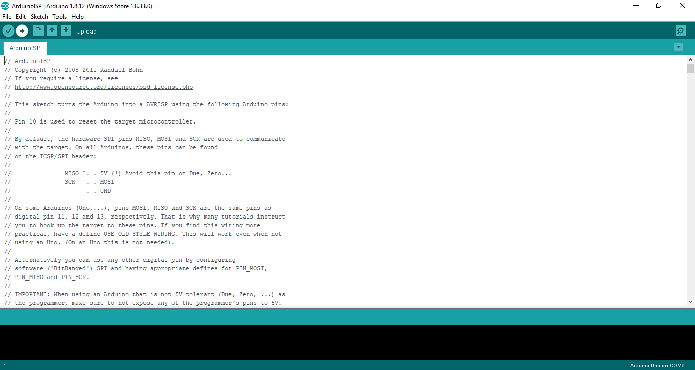
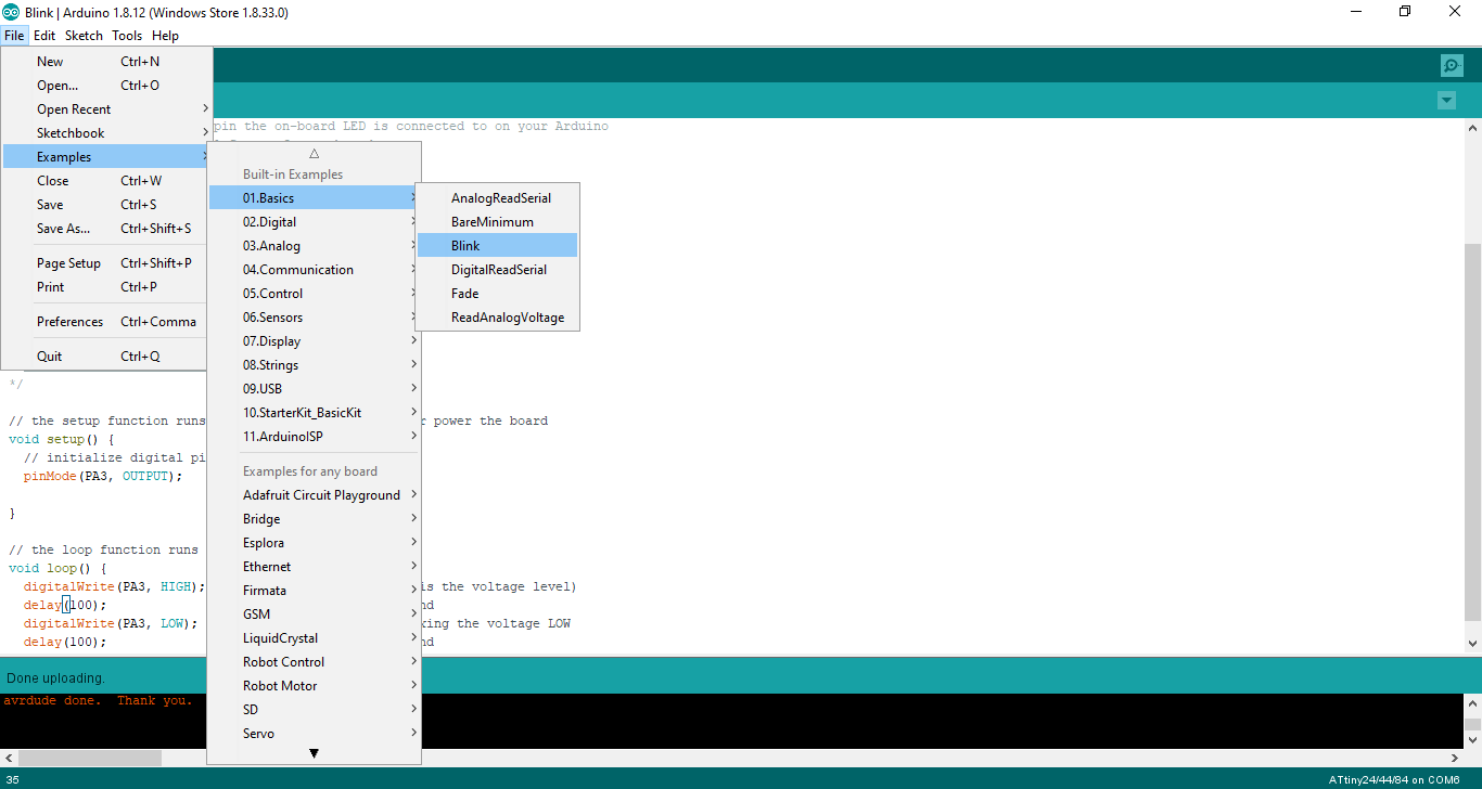
first step is to open the ArduinoISP
File >>Examples >>11.ArduinoISP >>ArduinoISP
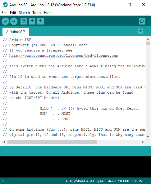
then the ArduinoISP will open
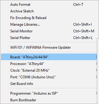
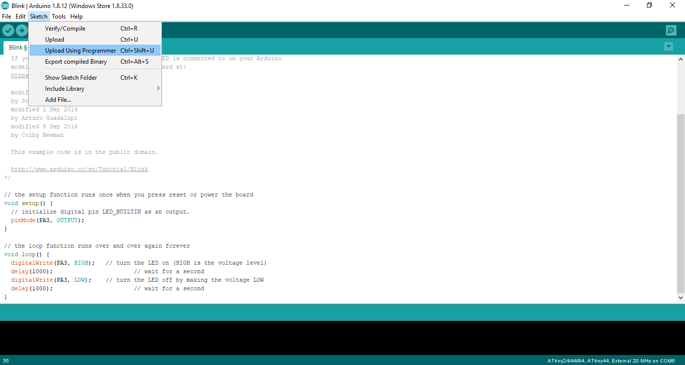
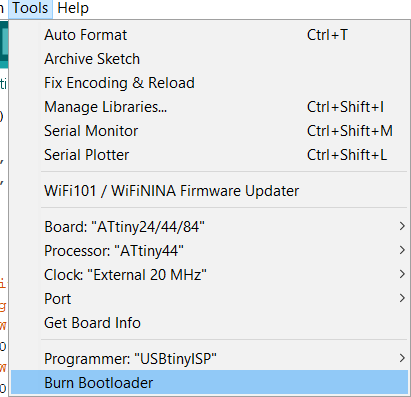
after this you should change the tools
Tools >> board >> Arduino UON chose the board that you have
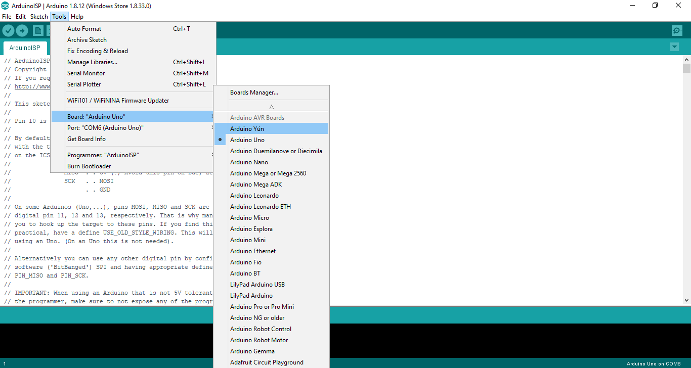
change the programmer to ArduinoISP
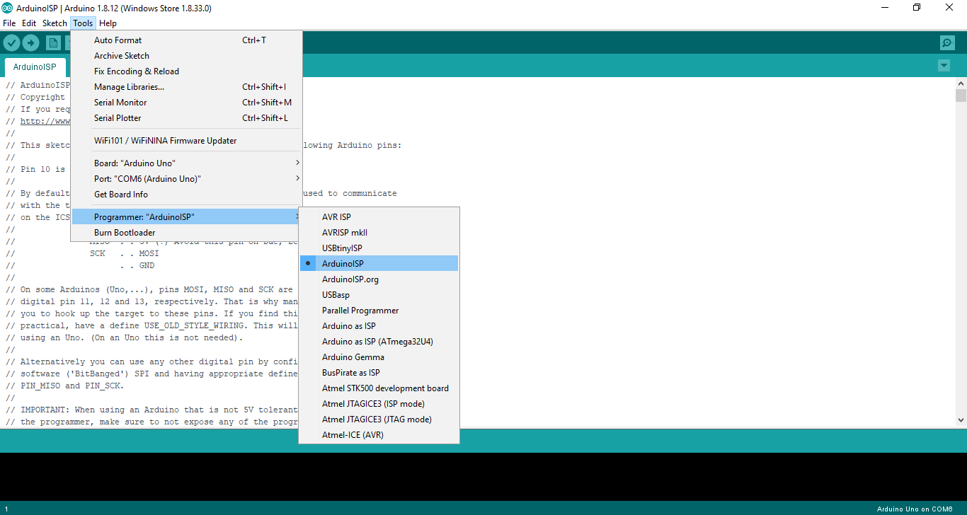
then click on the upload

done
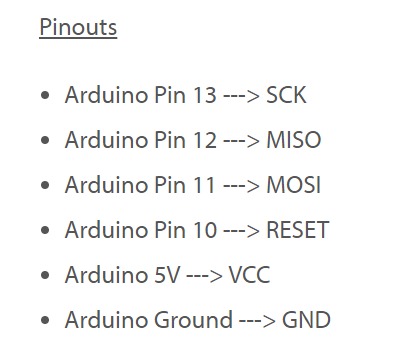
Connection
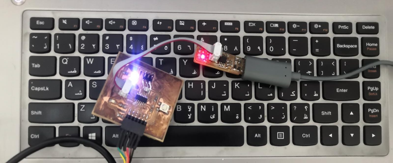
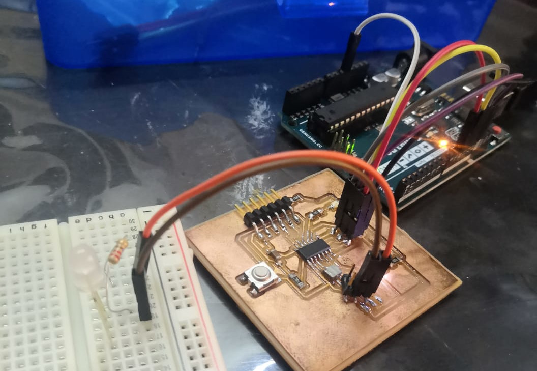
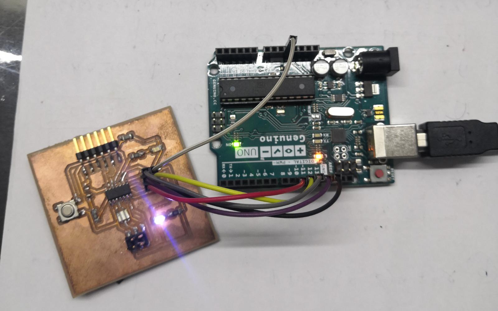
connect the programmer to my Circuit
After making the Arduino programmer I connected to my board as this pic
Program
then to chick if the programmer work I tested with blink code :
code
/*
  Blink

  Turns an LED on for one second, then off for one second, repeatedly.

  Most Arduinos have an on-board LED you can control. On the UNO, MEGA and ZERO
  it is attached to digital pin 13, on MKR1000 on pin 6. LED_BUILTIN is set to
  the correct LED pin independent of which board is used.
  If you want to know what pin the on-board LED is connected to on your Arduino
  model, check the Technical Specs of your board at:
  https://www.arduino.cc/en/Main/Products

  modified 8 May 2014
  by Scott Fitzgerald
  modified 2 Sep 2016
  by Arturo Guadalupi
  modified 8 Sep 2016
  by Colby Newman

  This example code is in the public domain.

  http://www.arduino.cc/en/Tutorial/Blink
*/

// the setup function runs once when you press reset or power the board
void setup() {
  // initialize digital pin LED_BUILTIN as an output.
  pinMode(PA3, OUTPUT);
}

// the loop function runs over and over again forever
void loop() {
  digitalWrite(PA3, HIGH);   // turn the LED on (HIGH is the voltage level)
  delay(1000);                       // wait for a second
  digitalWrite(PA3, LOW);    // turn the LED off by making the voltage LOW
  delay(1000);                       // wait for a second
}
Tinkercad
TinkerCAD is a free online service for creating basic 3D shapes and developing digital prototypes of electronic components. These prototypes include basic circuits with LED lights, buzzers, switches, and even light sensors. These prototypes can include a microprocessor as part of the design.
Tinkercad code blocks are visual blocks you can drag-and-drop to create Arduino programs. Using the Tinkercad Circuits simulator, you can test any code you create directly in the browser, before you build and program your devices with real physical components.
my code in the Tinkercad.
after I loge in website

I go to home then I press in the circuit
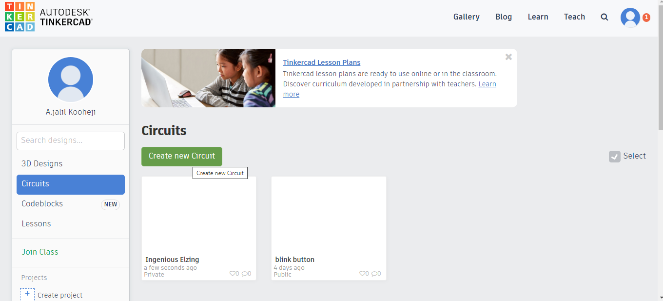
then create new circuit
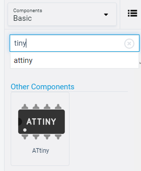
first I find the microcontroller that in by circuit.
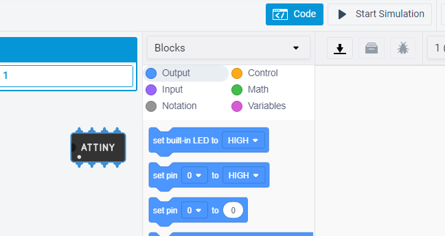
Block Code
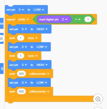
first is bleu block is set the light off then the orange block is a loop code and it mean when I press the button it enter the loop, the loop will make the light blink as you see as long I press the button the loop will continue.
then I press the download icon and I get the block code as normal code
Code
void setup()
{
  pinMode(3, OUTPUT);
  pinMode(2, INPUT);
}

void loop()
{
  digitalWrite(3, LOW);
  while (digitalRead(2) == 1) {
    digitalWrite(3, HIGH);
    delay(1000); // Wait for 1000 millisecond(s)
    digitalWrite(3, LOW);
    delay(1000); // Wait for 1000 millisecond(s)
    digitalWrite(3, HIGH);
    delay(500); // Wait for 500 millisecond(s)
    digitalWrite(3, LOW);
    delay(500); // Wait for 500 millisecond(s)
  }
}
here I just used the fabisp to program the PCB. as I upload it before but using febisp.