20. Project development
Assignment
Complete your final project, tracking your progress:
- what tasks have been completed, and what tasks remain?
- what has worked? what hasn’t?
- what questions need to be resolved?
- what will happen when?
- what have you learned?
Step-by-step progress
Task-list
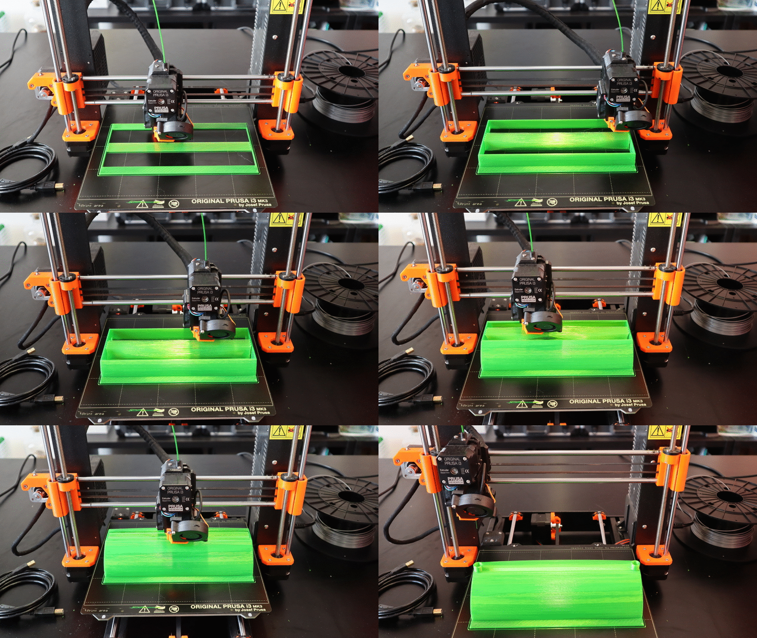
- 3D print planters to fill the pallet
- Make a PCB to connect the relay module, the power input and the level sensor
- Retrieve an AC-DC converter from a cellphone charger
- Make a PCB to connect the AC lines together
- LASER cut a bottle so the electronics can fit inside
- 3D print or LASER cut two bottle caps
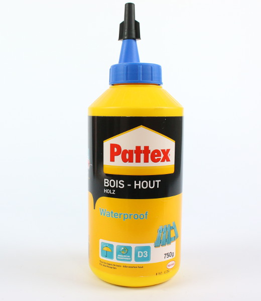
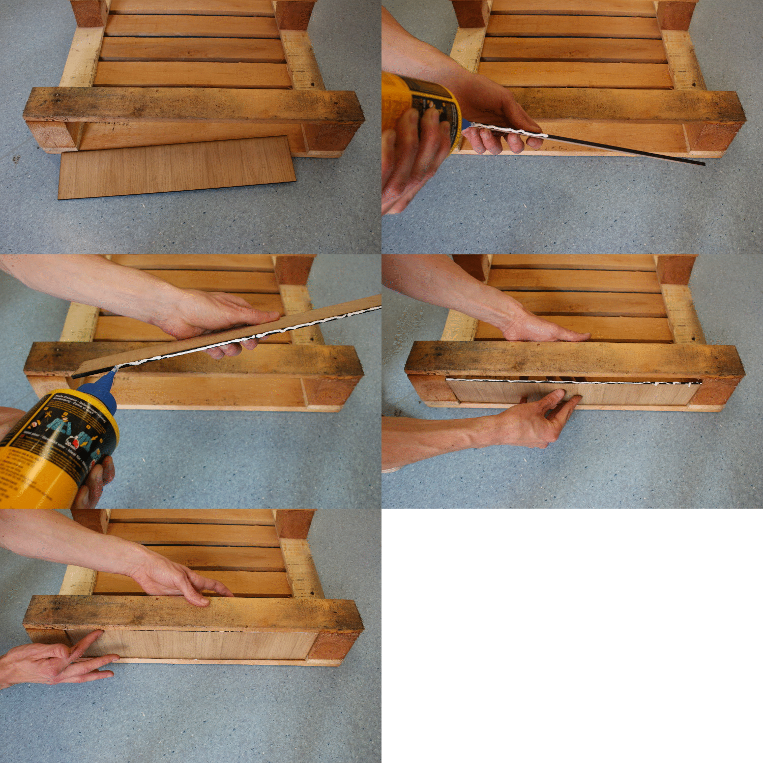
- Glue a wood panel at the bottom of the pallet
- Assembly
Gantt diagram
I dispatched the main tasks on two weeks (of 5 days) :

Some tasks may seem a bit over-sized in their duration but it is intentional. For example, I don’t want to do electrical wiring in a rush because I know I can burn the electronics if a make a small mistake. So I prefer to take my time to do it properly and avoid any potential extra-work.
3D printing planters
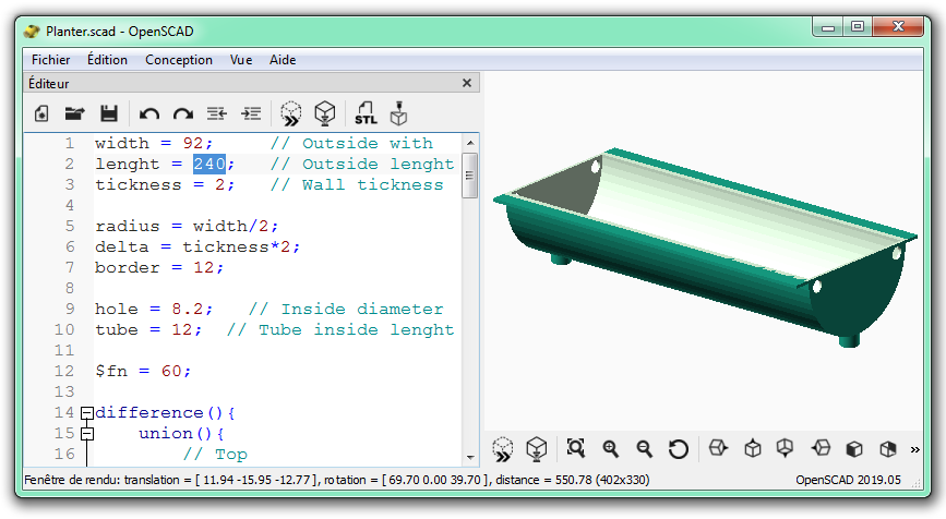
In Openscad, dimensions of the planter can be adjusted :
Making the electronics
AC-DC converter
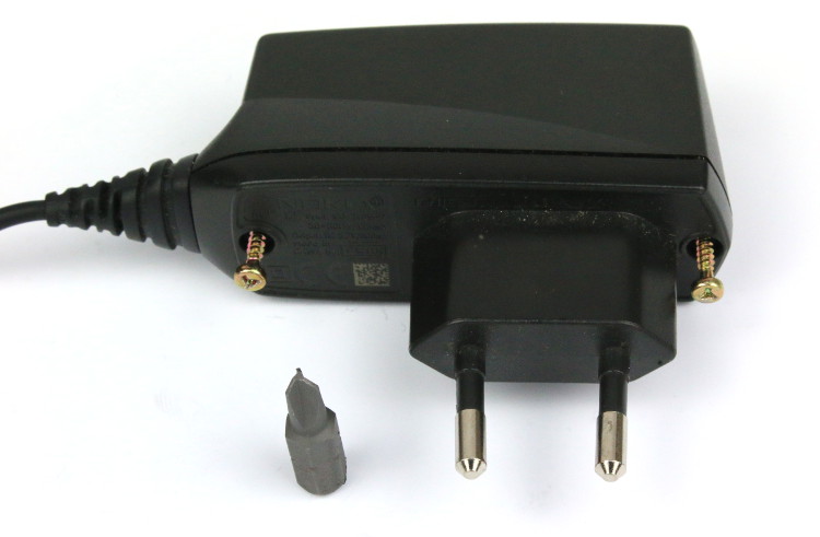
First I had to open the case. It can be an issue if you don’t have the good screwdriver. Here I used a TW1 (twisted wave) screwdriver head :
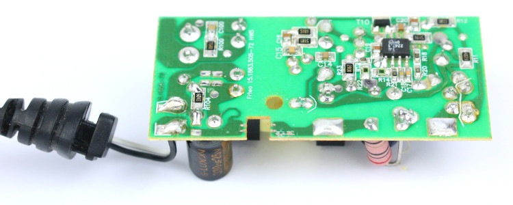
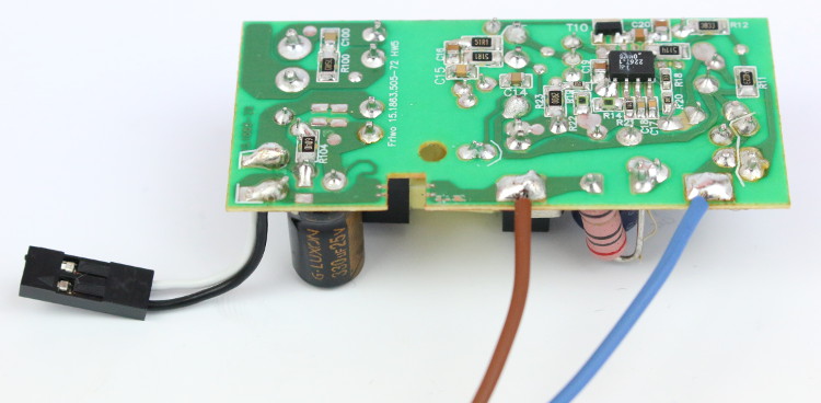
Then I removed the circuit from the case and identified where to connect the AC power.
I cut the output wire and stripped it :
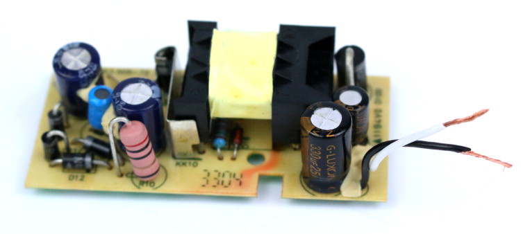
Then crimped it to make a connector :
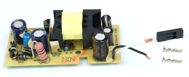
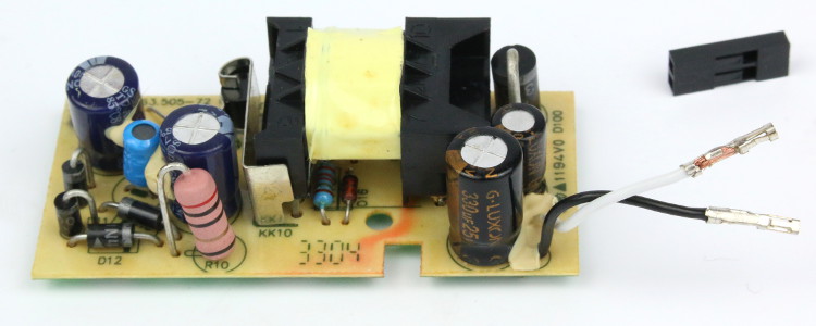
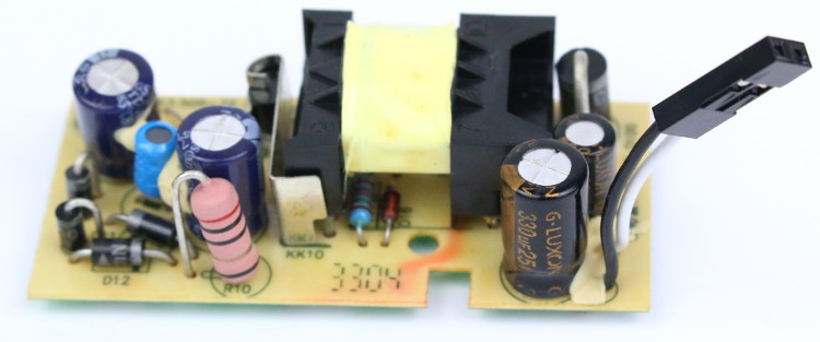
Finally, I soldered wires to the AC power input :

Adapter board
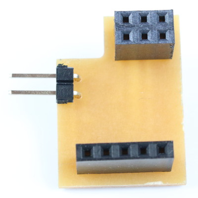
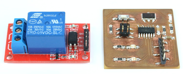
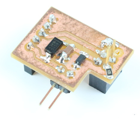
The voltage coming out of the cellphone charger is rated at 5v7, so I hat to lower it down. For this, I used a diode to drop the voltage of 0.7v and a zener diode (rated 5v1) to cut-off any potential over-voltage. I also added a 0.47µF capacitor, to increase stability.


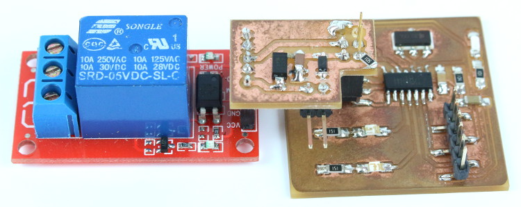
There are 3 connectors on this board :
- A 6-pins SPI socket, to be plugged on my HelloBoard (or another Arduino board).
- A 2-pins header, for the 5v supply from the AC-DC converter.
- A 5-pins socket, according to the relay module I had.
And the 2 pins from the SPI socket that rise on the other side like a header connector, these are for the water level sensor.
High-voltage patch board
This board has two roles :
- Split the power lines to the AC-DC converter and the pump.
- Rectify a line with a diode, to protect the pump

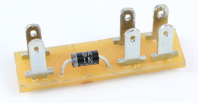
I used 2.8mm spade terminals. This connector is handy because the female plug comes with an insulating sleeve, and it won’t detach by accident.
Wiring
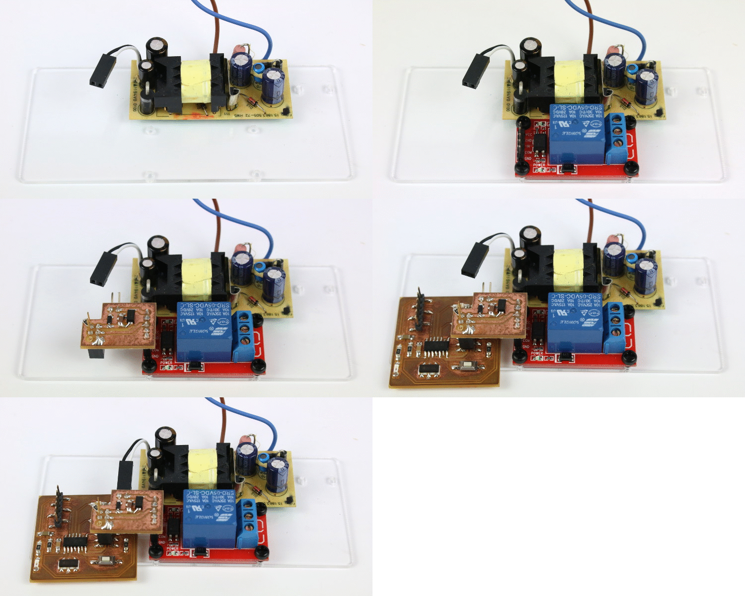
I attached the modules to the plastic panel and plugged the adapter board. Then I attached the high-voltage patch board with a cable tie :
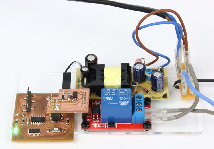
Here is the result, with the water pump connected through the relay :

Preparing the bottles
LASER-cut bottle
I cut some kind of door on this bottle’s side, so I can push the water pump and the electronics inside.
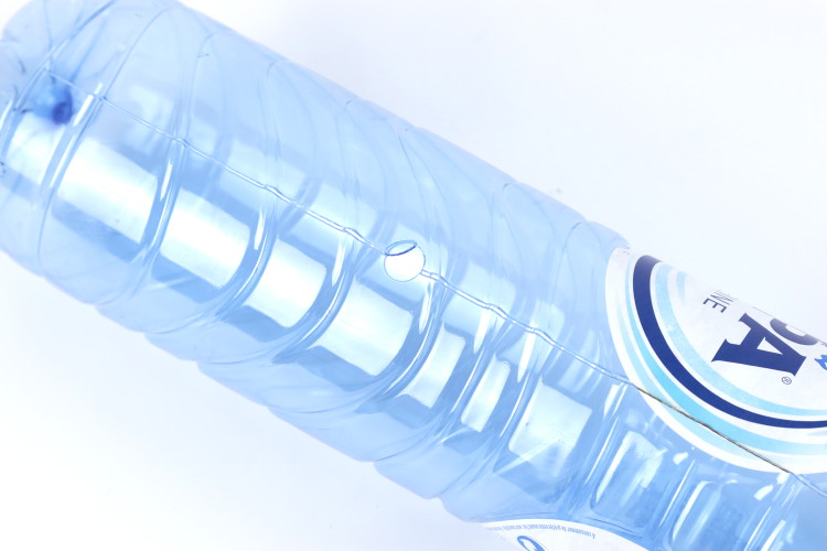
It also has two holes, one for the water outlet tubing and another for the power supply.
Bottle caps
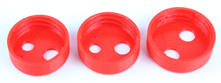
I tried to 3D print a cap with holes for water inlet/outlet tubings and level sensor. It was not easy to find the diameter that fits perfectly on the bottle, without leak. It took me 3 prototypes before getting a working print.
Then I found out it would be easier to LASER-cut the original cap :

Finally, I used those two caps in my project :
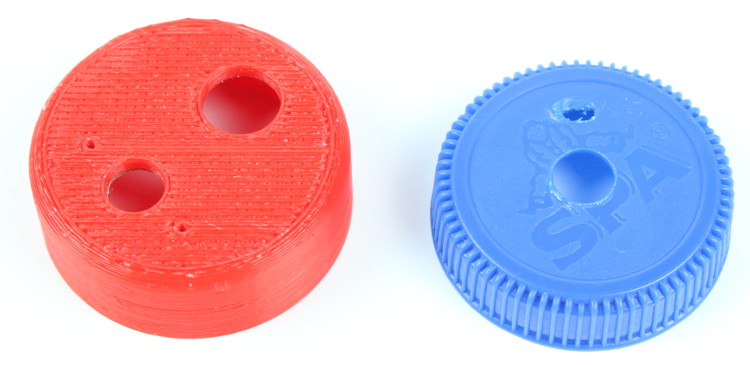
The 3D printed one is for the water tank, the LASER-cut one is for the bottle that contains the pump and other electronics.
Water level sensor
The level sensor is made of two PTFE insulated wires that are attached to the outlet tubing with a heat-shrink sleeve :

At first, I wanted to make a capacitive sensor using the step response example code. But the wires going from the tank to the controller board were too long for a clean capacitive sensing, so I decided to make a resistive sensor out of it.
For resistive sensing, I added a pull-down resistor to the ADC input signal :
Preparing the pallet
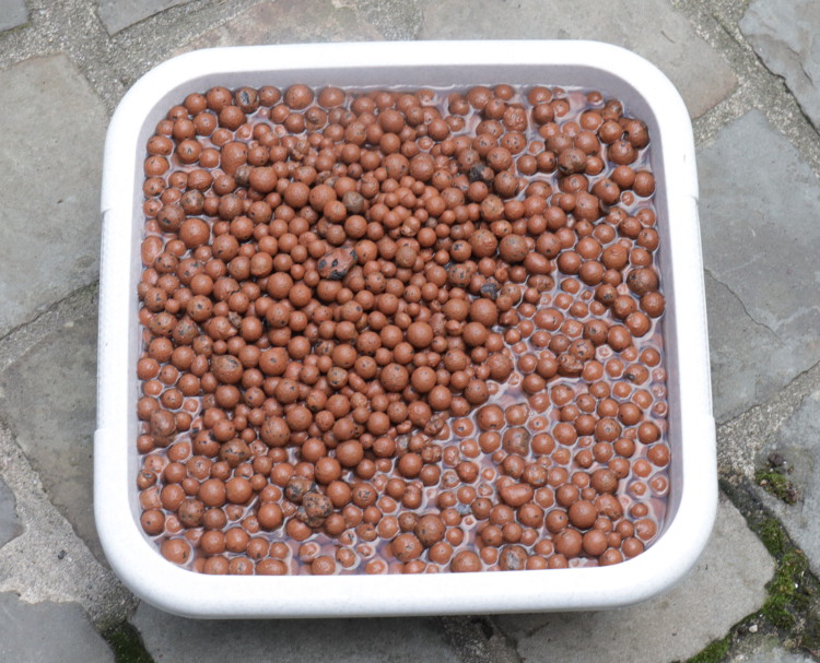
Preparing clay balls
If you intend to use clay balls as hydroponic media, you should leave it in water for at least 6 hours. It is necessary for the well-being of your plants, the clay balls must have the same pH as the water :
Then you should clean off clay powder and dust. For this, I punched holes at the bottom of the bag and I filled it with tap water :
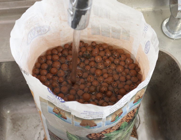
I let the water drain and fill the bag again (and again) until the water that leaves the bag is clean, without any clay powder.
Future improvements
The most necessary improvement is to add a second water level sensor. For now, the micro-controller can tell when the level is low. But if the level rise above the low-level sensor, pumping will start again. It would be better to have a high-level sensor, so pumping starts only when most of the water is already drained.
Next, I will find a proper way to seal the electronics inside the bottle. Then I will power it through a waterproof connector so the setup will be suitable for outdoor use.
Evaluation
What tasks remain ?
Everything in my task-list is completed, but I figured out I will have to check some new tasks :
- Seal tubings and fittings
- Seal the bottle that contains the electronics
- Add a second water sensor
What has worked ? Or not ?
These things worked as expected :
- 3D printed planters are well-dimensioned, it fits in the pallet and the tubing fits in the holes.
- The electronic circuit is acting as it is programmed to.
- The resistive water sensor is accurate.
- The water pump starts and stops, according to the water level.
These didn’t worked :
- 3D printed cap is not really water-tight.
- Capacitive measurement of the water level.
- 3D printed fittings are not water-tight.
What questions need to be resolved ?
- Will my setup be safe for outdoor use if I seal the electronics ?
- What if the water sensor get disconnected ?
- How can I prevent water overflow ?
- Is the 3D print (PLA/PET-G) suitable as planter, when continuously exposed to water ?
- Is this setup sufficient for hydroponic gardening ?
What will happen when ?
I can’t tell exactly when, but this is the plan and I will start it as soon as possible :
- The first thing I will do is re-print the fittings with a SLA printer, so it will be leak-proof.
- Then I will make a new adapter board that can read two water level sensors.
- Finally, I will attempt to grow aromatic plants indoor.
- If everything is working fine, I will update design files online.
What have you learned ?
- Never under-estimate the time needed to complete a project.
- Expect documentation to be even more time consuming.