9. Embedded programming
Assignment
- Read a microcontroller data sheet
- Program your board to do something,
- with as many different programming languages
- and programming environments as possible
Reading the datasheet
I read the ATtiny24/44/84 datasheet because I used an ATtiny84 to make my HelloBoard.
The most interesting documentation I found in this datasheet is about the clock system (chap. 6) :
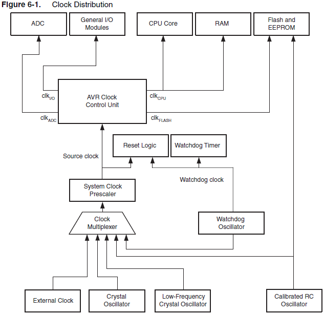
In the clock distribution diagram, you can see that there is only one clk I/O to be used for timers, interrupts or PWM.
As I often need to use timers for triggering interrupts, I want to know more about it…
In chapter 11 and 12, I found the diagrams of the timers/counters. Here is the 8-bit one :
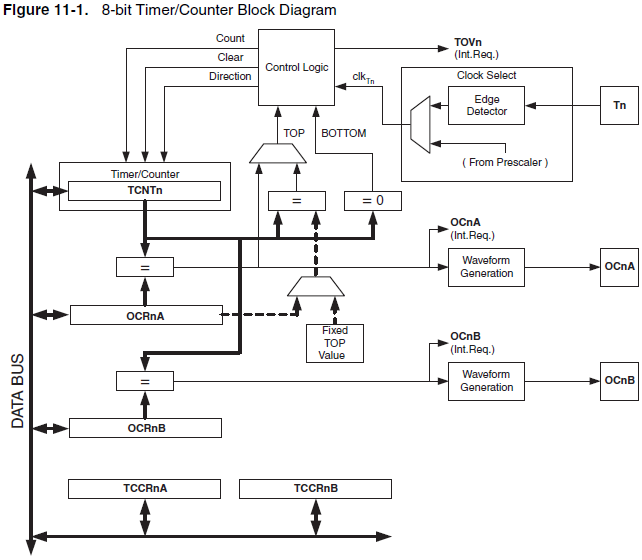
To make it easier to read, I looked for the register’s names :
- TCNT means Timer/Counter (the register that increments with time)
- OCR means Output Compare Register
- TCCR means Timer/Counter Control Register
- OC means Output Compare (it can be a signal for interrupt request, or a physical output pin)
- TOV means Timer/Counter Overflow flag
And here is the 16-bit one :
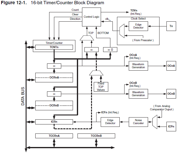
The only difference in these diagrams is that Timer/Counter1 has a ICRn (Input Capture Unit), and I don’t know what it’s meant for.
I also found the diagram explaining the Output Compare Unit :
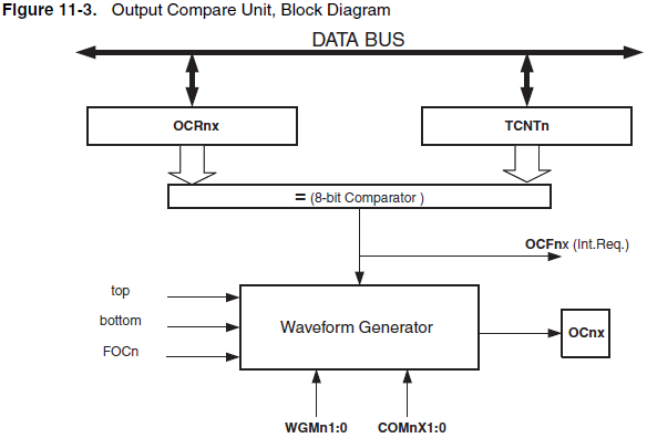
(16-bit version’s diagram is so complicated that I don’t want to display it here.)
In this diagram :
- FOC means Force Output Compare
- OCF means Output Compare Flag
- WGM means Waveform Generator Match
- COM means Compare Output Mode
In subscripts, n is for the number of the Timer/Counter (0 or 1) and x is for an identification letter (A or B).
In chapter 13, a diagram shows how a prescaler divides the I/O clock frequency for each Timer/Counter, according how you set the Clock Select register :
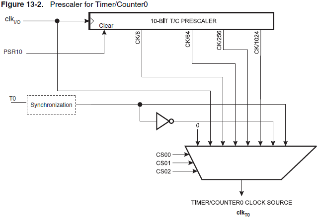
Now, I won’t go into further details because I am mostly interested in controlling interrupts. In chapter 9, I found the Interrupt Vectors table :
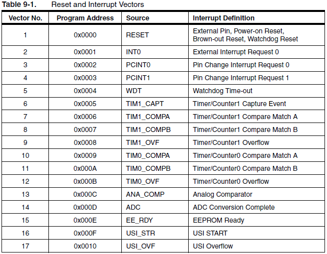
It shows the 7 interrupt vectors from Timer/Counter0 (TIM0_…) and Timer/Counter1 (TIM1_…).
The names and definitions are explicit enough for me to understand what each vector is related to, but it doesn’t tell the link between the Timer/Counter registers and the interrupt vectors.
And I could not find a clear explanation in the datasheet.
What I don’t understand
- What’s the use of an Input Capture Unit ?
- what’s the use of a Compare Match Output Unit ?
- Why is timing setup so complicated ? It would need some kind of flow-chart to guide you into the process.
What I learned
- Each timer/counter can have different prescaler settings.
- Each timer/counter has two independent output compare units.
- The timer/counter1 allows 16-bit PWM (it can be useful for controlling a servo with better precision).
Programming with Arduino IDE
I did it to test my HelloBoard in the week7 assignment.
Programming with WinAVR
Makefile
I first edited the .make files to make it work with the ATtiny84. I had to rename it Makefile so it can work with WinAVR.
This is how it looks like for the hello.ftdi.44.echo.c example :
PROJECT=hello.ftdi.44.echo
SOURCES=$(PROJECT).c
MMCU=attiny84
F_CPU = 20000000

CFLAGS=-mmcu=$(MMCU) -Wall -Os -DF_CPU=$(F_CPU)

$(PROJECT).hex: $(PROJECT).out
    avr-objcopy -O ihex $(PROJECT).out $(PROJECT).c.hex;\
    avr-size --mcu=$(MMCU) --format=avr $(PROJECT).out

$(PROJECT).out: $(SOURCES)
    avr-gcc $(CFLAGS) -I./ -o $(PROJECT).out $(SOURCES)

flash: $(PROJECT).hex
    avrdude -p t84 -P usb -c usbtiny -U flash:w:$(PROJECT).c.hex

fuses: $(PROJECT).hex
    avrdude -p t84 -P usb -c usbtiny -U lfuse:w:0x5E:m
I removed the commands that are not related to the USBtinyISP programmer. I renamed program-usbtiny and program-usbtiny-fuses to make it shorter.
After editing the C code, I have to open the command prompt, use cd to go into the firmware directory, and type these commands :
- make to build the .hex and .out files
- flash to send it to the programmer
- fuses to set the µcontroller fuses
C program
I tried to edit the hello.ftdi.44 C codes to make it :
- Light a different LED when receiving a character 0 or 1 on serial port
- Print the status of the push-button input on serial port
- Use the INT0 interupt to switch from one LED to another
- Use the INT0 interupt to print on serial port when the button is pushed
The last step is tricky because the serial port input also uses interupts. In fact, the push-button interupt function only shows up when the other interupt is set by receiving data on the serial port input.
I think it’s because of the get_char function that blocks everything when doing while(pin_test(*pins,pin)).
With the while removed, the function still receives data from the ftdi but before that, it shows up an empty character.
So I had to filter it by adding a condition in the ISR(PCINT0_vect) function. The condition is that the received byte must be greater than 32 (first of readables characters).
Assembler programming
In order to try compiling an assembler code, I am reading this micro beginner course.
But I don’t want to use AtmelStudio so I had to download gavrasm as a compiler.
Unzip gavrasm
I downloaded the executable Windows-64-Bit version 4.1 and extracted the files in C:\gavrasm (there are 3 files but only gavrasm.exe is necessary).
Makefile
Now I have to tell where is my assembler compiler in the Makefile.
Here is the Makefile for the hello.ftdi.44.echo.asm example :
PROJECT=hello.ftdi.44.echo
SOURCES=$(PROJECT).asm
MMCU=attiny84
F_CPU = 20000000

CFLAGS=-mmcu=$(MMCU) -Wall -Os -DF_CPU=$(F_CPU)

$(PROJECT).hex: $(SOURCES)
    C:\gavrasm\gavrasm.exe $(SOURCES)

flash: $(PROJECT).hex
    avrdude -p t84 -P usb -c usbtiny -U flash:w:$(PROJECT).hex

fuses: $(PROJECT).hex
    avrdude -p t84 -P usb -c usbtiny -U lfuse:w:0x5E:m
Files
The C file I made (it’s just an improvement of hello.ftdi.44.c) is archived into hello.ftdi.interrupt.zip