3. Computer Aided design
Assignment
- Model a possible final project
- Post it on your class page
Ambition
I started the assignment using Solidworks because I expected to do it quickly and have some spare time to do it again in Openscad. This is what I planned to do with Solidworks :
- Model separated parts
- Make an assembly of a project with parts
- Render an animation of the assembly
Then try do make the same design in Openscad, to have a parametric way of generating plans :
- 2D plans to laser-cut panels, according to the lenght of rails
- 3D model of the connection cubes, according to the thickness of panels
Using Solidworks
CAD files
The files for this design are archived in FumeHood.zip. I can only guarantee compatibility with Solidworks 2016.
Modeling parts
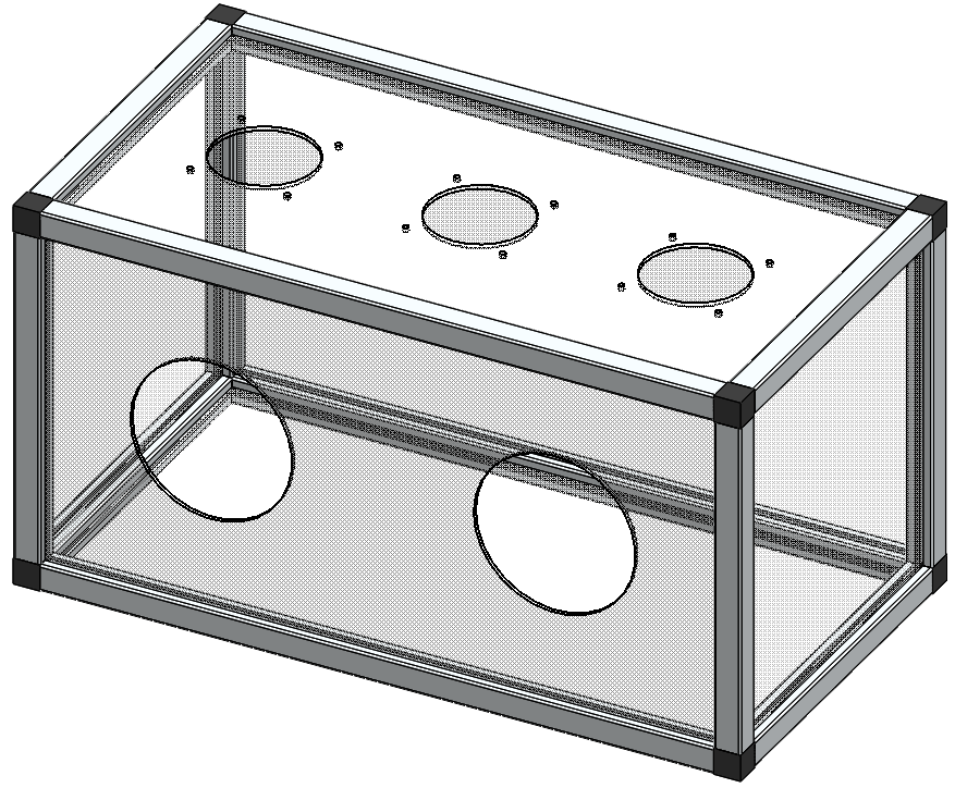
I used 7 differents parts in order to assemble it into a glove-box with fan outlets at the top :
- Short rail (used 8 times)
- Long rail (used 4 times)
- Connection cube (used 8 times)
- Front panel (used once)
- Small side panel (used twice)
- Wide side panel (used twice)
- Top panel (used once)

I downloaded connection cube and rails from Thorlabs website.
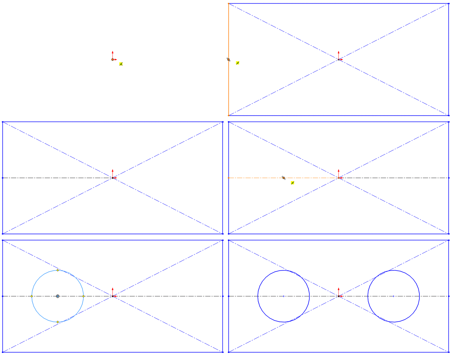
And I designed the panels, starting from 2D sketches :
Assembly and animation
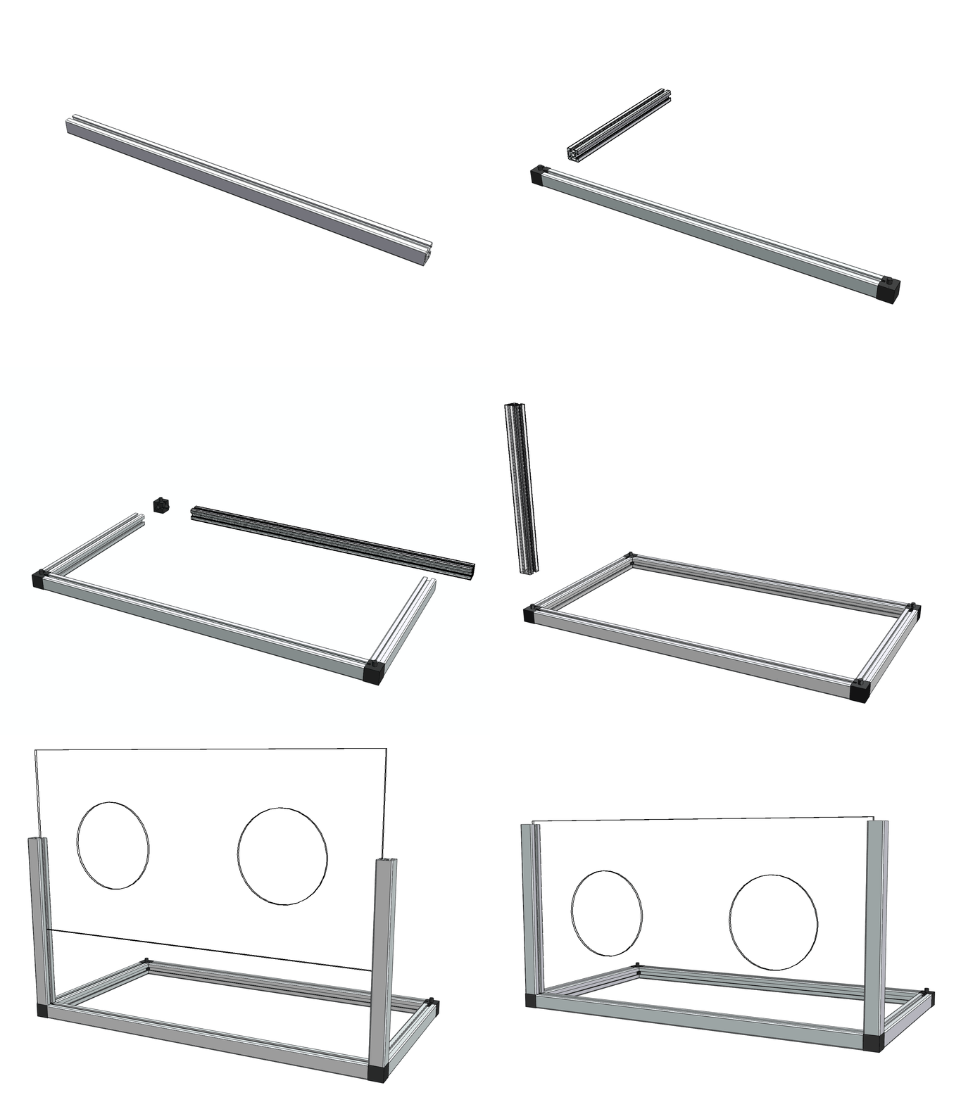
Then I assembled the parts into a box :
I tried to render an animation of the assembly everytime I added a component, but it was a little bit tricky.
I had to restart from the beginning 3 times before I understood how to animate the distance between parts without creating conflicts.
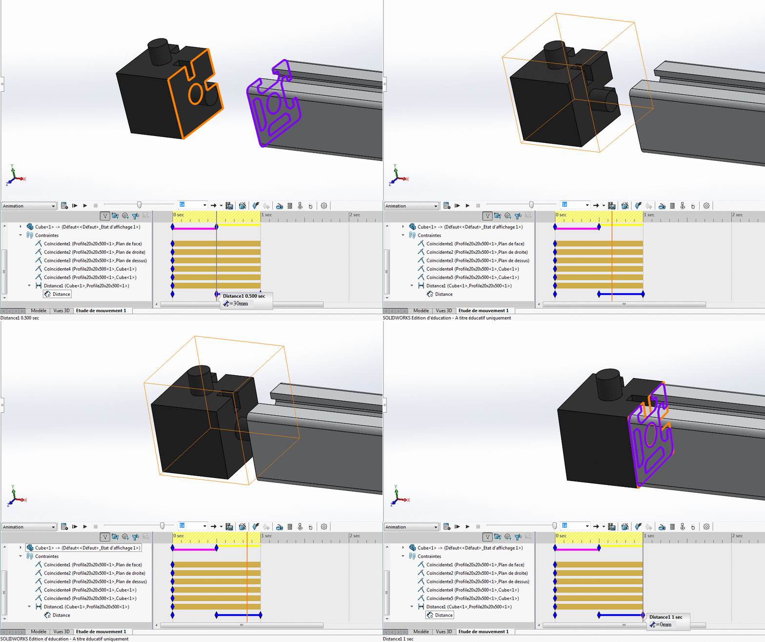
In the “Motion study” frame, you can add a “key” where you want to change the distance. The gray/orange vertical line indicates your position in the time-line.
If you change some parameter, a key will be created at this position.
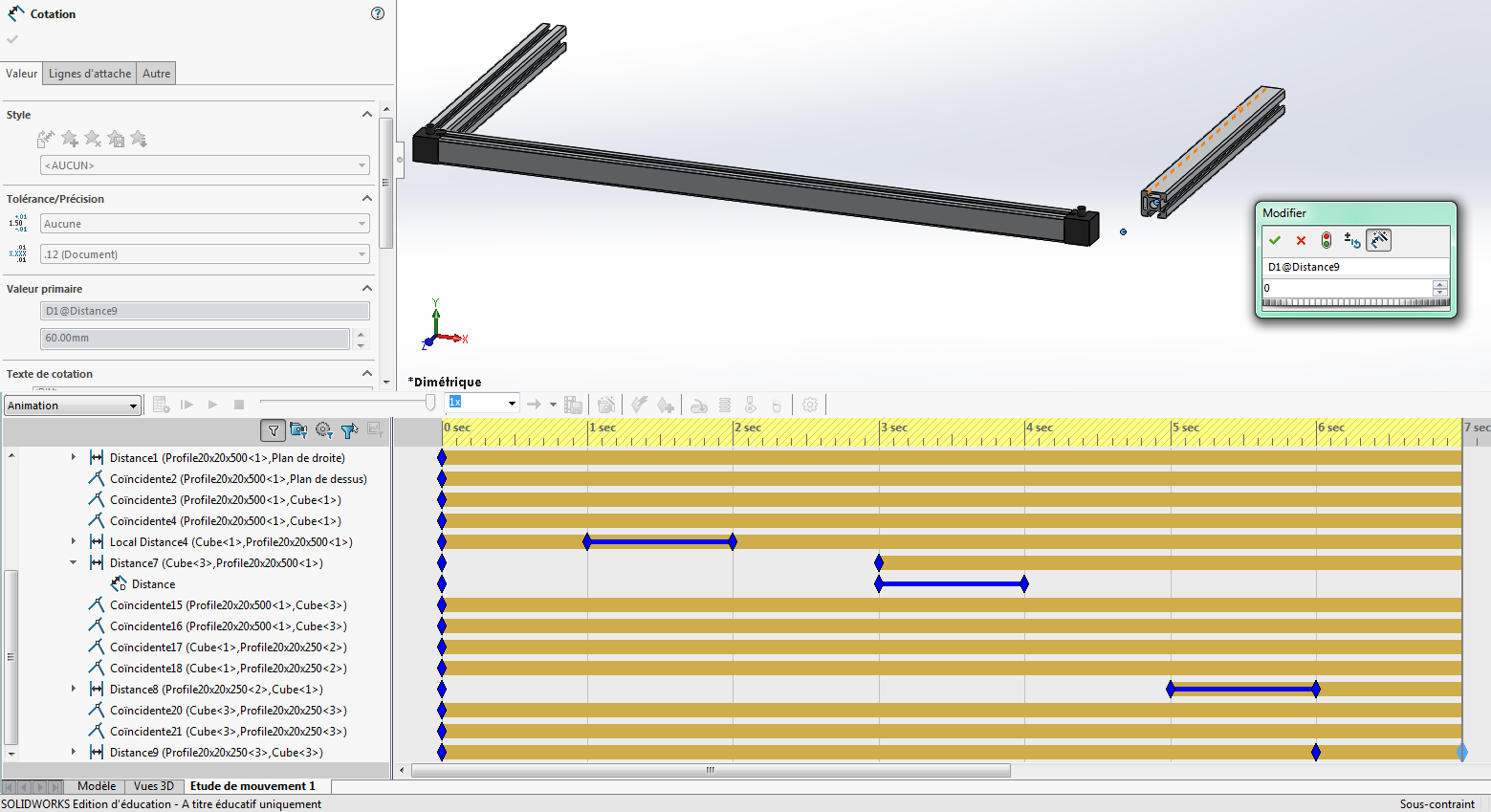 Double-clicking on a key is the shortest way to change the associated parameter.
Note that you may have some strange effects when you change the distance. If you see the object in its old position and don’t understand why, you may have to click the Calculate button.

Then every path will be updated correctly.
Another problem that I faced was the orientation of the “camera”. The assembly got out of screen when I tried to export the movie. To get a good orientation, you should add some keys to the camera line. Double-clicking on the camera icon will open a frame that shows the virtual camera position and a preview of the output.
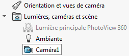
It also allows you to change the picture ratio (I choosed 4:3).
Once completed, the animation can be exported in AVI movie, or as image stack. For the website, I wanted to make an animated GIF so I exported an AVI and converted it into a GIF using OpenAviToGif.
Here is the result :
Parametric design
Thanks to Christophe, I discovered that a design can be made parametric in Solidworks, using Tools -> Equations. Then I tried to make the slots in my connection cube fit any given panel thickness. But I found out that variables can only be used in 2D drawings, not for the depth of an extrusion (to be confirmed…).
Using Openscad
Still had no time to design the box in Openscad but I hope to do so. I know it can be used for 2D projection, as explained in the OpenSCAD User Manual.
I did a 2D parametric design for Week 4 assignment.
Using CorelDraw
For my final project, I had many parts to LASER-cut. We use CorelDraw as an interface to the LASER-cutter because it has the same color-space as the Epilog Mini so it can do color mapping. Also, CorelDraw is very handy to manipulate vector drawings.
In this example, I will only use these tools for drawing :

To draw a straight line, from a point to another.

To draw an ellipse. To make a circle out of it, I just type it’s dimensions here :

If the padlock is closed, height and width will be scaled proportionally to the original ratio. To change dimensions freely, click on the padlock to open it.
For LASER-cutting, we don’t want to plot unnecessary lines. So, I joined all the shapes in a single on with the Join tool :

For my final project, I had to draw an opening for a plastic bottle. This is how it looked like :

And here is the result :
