17. Machine design
This week I worked on defining my final project idea and started to getting used to the documentation process.
Assignment
- Actuate and automate your machine
- Document the group project and your individual contribution
Group project
Group assignment is documented on it’s dedicated page and on the mechanical design group page.
Extruder implementation
This is the main part of our machine design, we want to add a syringe pump to the 4xiDraw and use it as an extruder (like in a 3D printer).
Problem
At first, I wanted to use the Grbl shield to control the extruder motor. It was complicated because the Grbl firmware expect to receive a distance to move on the specified axis. In this case, I just want to extrude as long as the Z-axis is down (in writing position).
I could have generated the g-code in a way that computes the distance to move the extruder according to the lenght of the path, for every segment that will be plotted. But it looked too complicated.
Solution
We decided to use a separated microcontroller that will move the extruder when the Z-axis is in plotting position.
To do so, I had two options :
- Read the voltage that is applied to the servo.
- Use an additional g-code command to turn on/off an output on the Grbl shield.
I decided to connect the microcontroller to the CoolEn (coolant enable) output of the Grbl shield. So it will enable/disable the extruder as it would do for a coolant control.
Now we have to generate the g-code this way :
- When drawing, send M3 S0 to move down the Z-axis, then M8 to start extrusion.
- When jogging, send M9 to stop extrusion, then M3 S100 to move up the Z-axis.
It was done with some modifications of the Path to G-code module in mods.
Hardware
Extrusion signal
The extrusion signal is wired from the CoolEn (coolant enable) output of the Grbl shield to Arduino’s pin 2 (INT0) with a pull-down resistor.
Limit switch
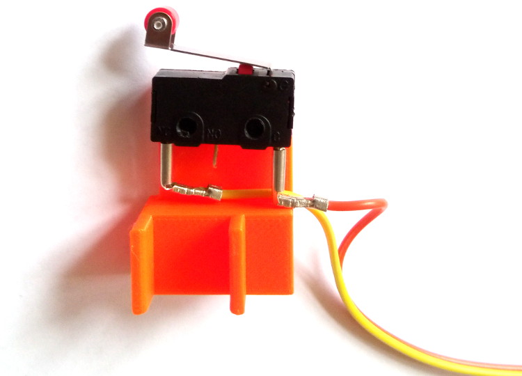
I added a limit switch to the syringe pump :

It is wired as normally-closed and connected to Arduino’s pin 3 (INT1).
Solidworks part, STL and g-code files are archived in SyringeStop.zip
User interface
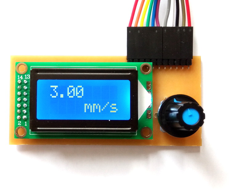
In order to allow tuning of the extrusion speed, I made an user interface board :

EAGLE schematic and board are archived in UserInterface.zip.
- The LCD is wired to Arduino’s pins 8 → 13.
- The rotary encoder is wired to Arduino’s pins 4 → 6.
Motor driver
I used an EasyDriver v4.4 module to control the stepper motor.
I left MS1 and MS2 unconnected, so the microstepping is set to ⅛.
DIR and STEP inputs are wired to Arduino’s pins A0 and A1.
Microcontroller
Everything is connected to a compact Arduino clone.
I choosed it because it has the advantage of providing power pins for each I/O pin, so it makes wiring a lot easier.
Software
Here is the actual Arduino code :
#include <LiquidCrystal.h>
#include <ClickEncoder.h>
#include <TimerOne.h>

#define stp A1  // Step input of the EasyDriver module
#define dir A0  // Direction input of the EasyDriver module

ClickEncoder *encoder;
void timerIsr() {
  encoder->service();
}

//                RS  E  D4  D5  D6  D7
LiquidCrystal lcd(13, 12, 8, 9, 10, 11);

int feedrate = 30, last = 0, ms;
float printRate = 3.0;
volatile boolean flag = false, stopped = false;

void setup()
{
  pinMode(stp, OUTPUT);
  pinMode(dir, OUTPUT);
  digitalWrite(stp, LOW);
  digitalWrite(dir, HIGH);

  encoder = new ClickEncoder(5, 4, 6, 1);
  Timer1.initialize(1000);
  Timer1.attachInterrupt(timerIsr);

  lcd.begin(8, 2);
  lcd.setCursor(4, 1);
  lcd.print("mm/s");

  pinMode(2, INPUT);
  pinMode(3, INPUT_PULLUP);
  attachInterrupt(digitalPinToInterrupt(2), rocker, CHANGE);
  attachInterrupt(digitalPinToInterrupt(3), limit, CHANGE);
}

void loop()
{
  if (flag and not stopped) {
    digitalWrite(stp, HIGH);
    delayMicroseconds(ms);
    digitalWrite(stp, LOW);
    delayMicroseconds(ms);
  }
  else {
    feedrate += encoder->getValue();
    if (feedrate != last) {
      if (feedrate < 1) {
        feedrate = 1;
      }
      if (feedrate > 50) {
        feedrate = 50;
      }

      printRate = feedrate / 10.0;
      lcd.setCursor(0, 0);
      lcd.print(printRate);

      ms = 5000 / feedrate;

      last = feedrate;
    }
    if (!digitalRead(6)) {
      digitalWrite(dir, LOW);
      digitalWrite(stp, HIGH);
      delayMicroseconds(ms);
      digitalWrite(stp, LOW);
      delayMicroseconds(ms);
    }
  }
}

void rocker() {
  flag = digitalRead(2);
  digitalWrite(dir, HIGH);
}

void limit() {
  stopped = digitalRead(3);
}