6. 3D Scanning and printing
Assignment
- Design and 3D print an object that could not be made subtractively
- 3D scan an object
- and optionally print it
Group assignment is documented on it’s dedicated page.
Machines in the lab
3D printers :
3D scanners :
3D print
Design :
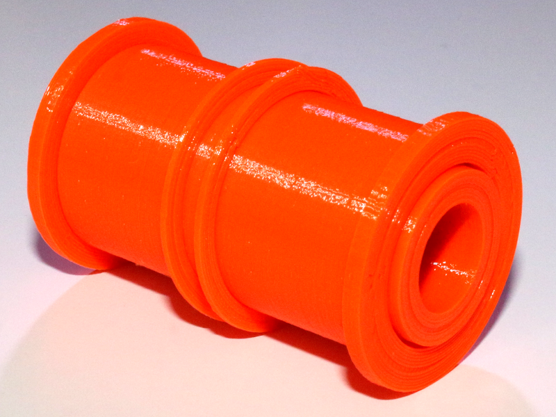
I made these two parts that are meant to be screwed together. The second part could not be made subtractively because it’s inside body is free-wheeling.

Print result :
I printed the parts with a Prusa i3 MK3, with 0.15mm resolution.
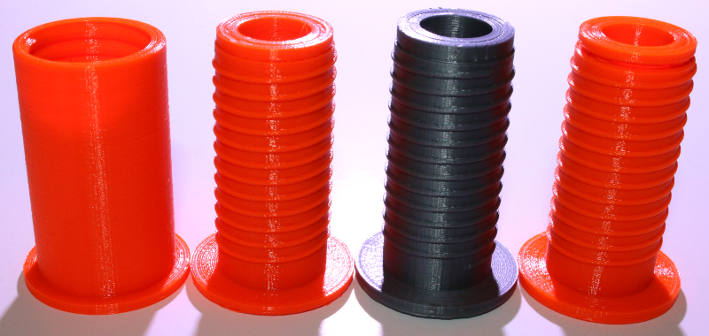
Orange prints are made of PETG and the grey print is made of PLA.
I first used a clearance of 0.2mm for the moving parts but welding happened and i could not move it. I tought it was because of PETG so I tried to print the same part in PLA but it also got weld. Finally, I had to use a 0.4mm clearance to have a free-wheeling device.
3D scan
I tried to scan the printed part with the outside thread because I wanted to see if I could print it from the scan and screw it as the original one.
NextEngine
I got these results form NextEngine Scan Studio :
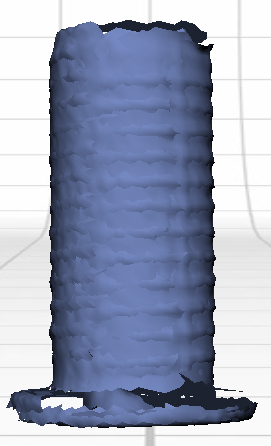
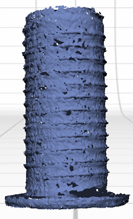
The low-definition scan looks too smooth and the high-definition one looks too sharp.
I would like to find a better resolution setting for the 3D scan…
But something is wrong with the NextEngine scanner or Scan Studio software. Most of the time, captures are misaligned and there is no way to align it :
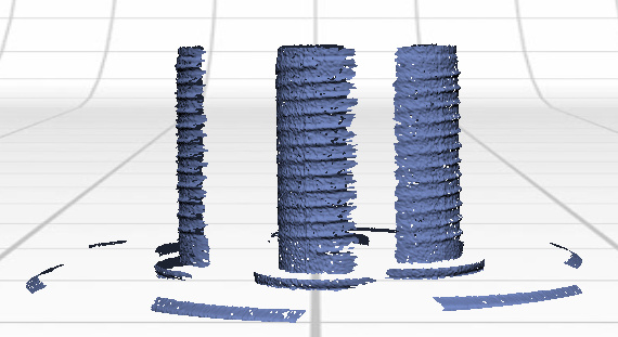
That’s very disappointing for such an expensive 3D scanner. I would like to fix it but I don’t know what to do. The bug probably comes from the (proprietary) software and there is no update for it.
3D Systems Sense 2
I tried to scan the printed part with the 3D Systems Sense 2 but it was loosing track of the target object every time and I could not get half of the volume :
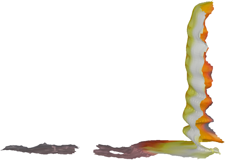
I looked for the technical specifications of the scanner and I found out there are scan volume limitations :
And the minimum is larger than my 3D printed part.
So I asked a colleague to make a scan of my head, and it was a lot easier to catch :
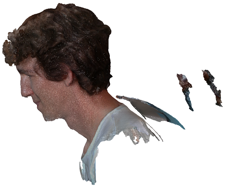
But there are some misaligned surfaces that need to be removed.
To do so, I orient the model in a way that isolate these separated surfaces, then I click on the Erase icon :

And I draw on the surface that I want to erase :
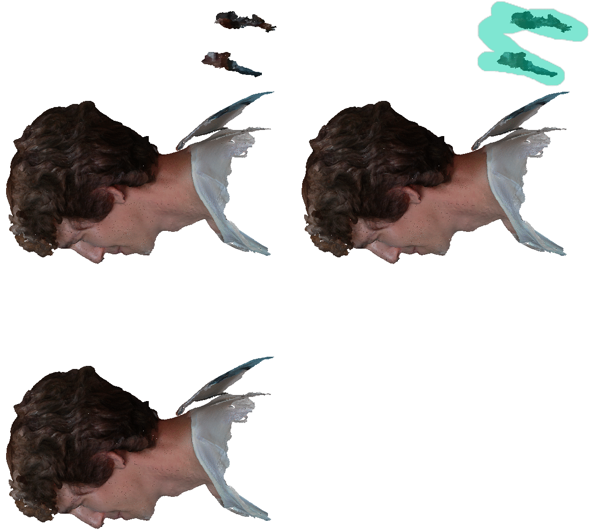
Then I click on the Apply icon :

Changes would be discarded if I did not clicked on Apply.
After removing all the unwanted surfaces, I used the Cut tool to make a straight cut at the bottom of the model :

Then I clicked the Repair icon :

And used the Make solid tool to fill the holes :
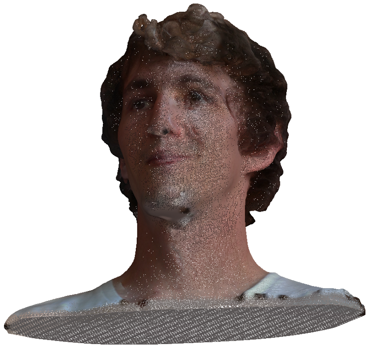
Now it’s solid, it can be exported to a STL file for 3D printing.
