12. Output devices
Assignment
Individual assignment :
- add an output device to a microcontroller board you’ve designed,
- and program it to do something
Group assignment :
- measure the power consumption of an output device
Device type
I want to use a 10 LEDs bargraph display because I think it is the most explicit way to show if you are getting out of range :
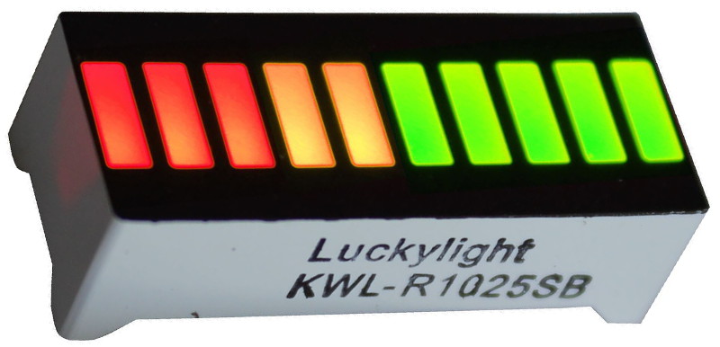
I bought it on eBay for less than 1€/pcs. If you want to do it yourself, you just need 10 LEDs.
To control it, I will make a board with a LM3914 driver (but it can be replaced with LM3915 or LM3916).
First PCB
First design
I designed two boards in EAGLE :

The small one is for connecting the bargraph module with a single-row header. The second is for the LM3914 driver.
These board are meant to be connected at a right-angle, so I can place many displays on a front panel without having to care about the width of the PCB.
Here is the schematic :

First fail
There are a lot of open contacts and the display is not acting as expected :
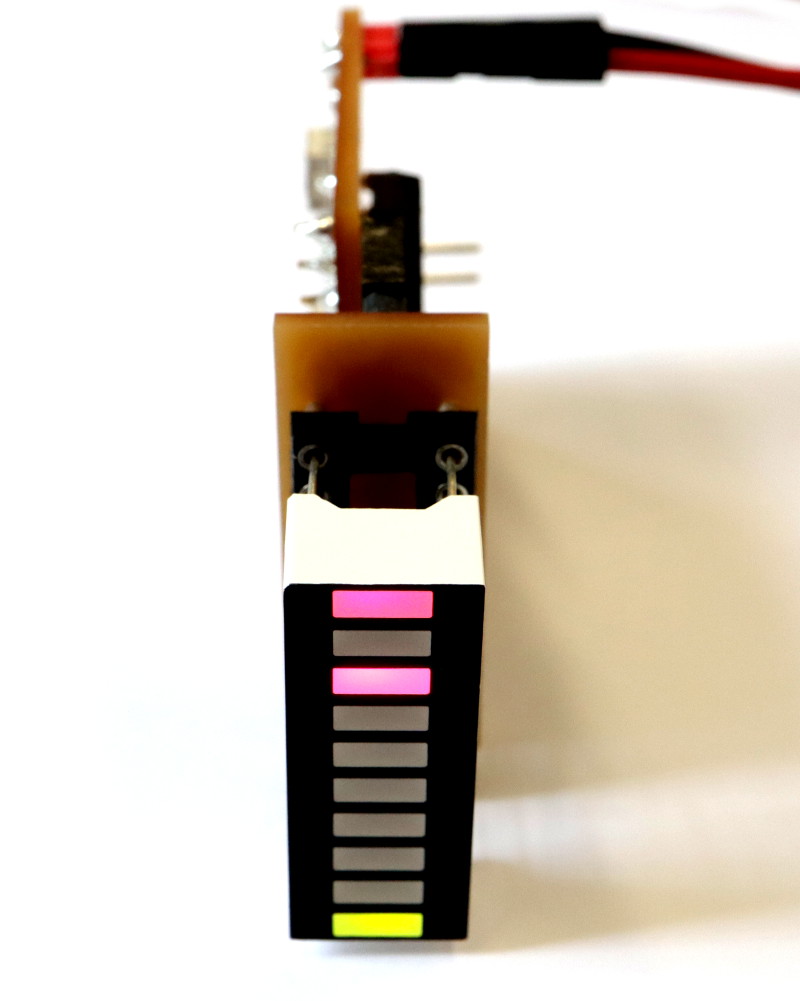
And the schematic, that was inspired from the LM3914 datasheet, is not suitable for the settings that I want to do. So I started a second circuit…
Second PCB
Second design
This circuit is inspired from this website (in French, this is where I learned electronics).
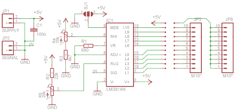
It has the advantage that you can set the upper and lower limits where the LEDs should light up.
Here is the second PCB :
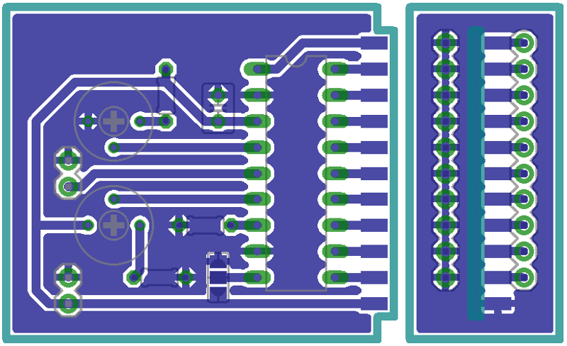
And how it will look like, once milled and assembled :

Second fail
I exported g-code from EAGLE using the pcb-gcode plugin, but when I selected the Generate bottom outlines, I also selected Mirror (an old habit from UV mask etching). So the circuit was milled mirrored :
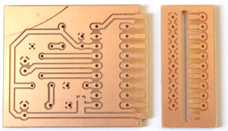
Third PCB
Third design
I kept the same schematic but I added little improvements to the PCB :
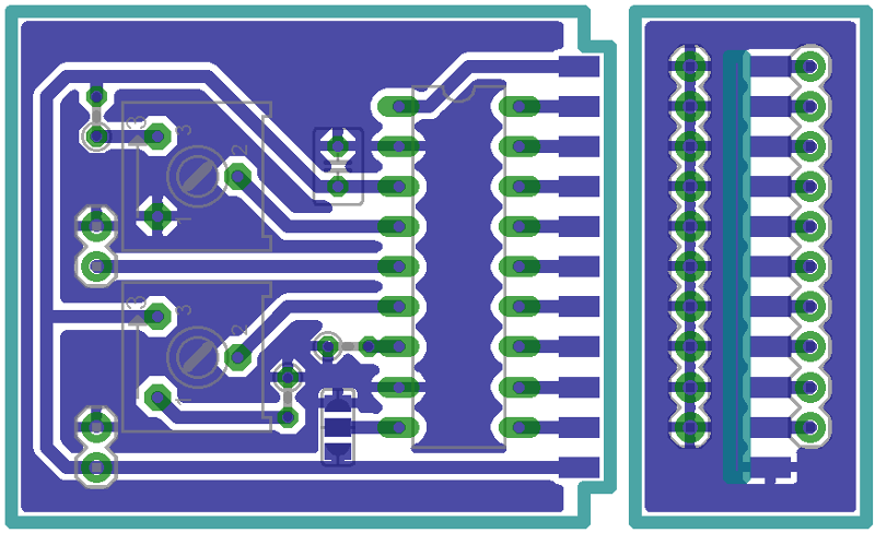
And I milled it without any trouble, except for the holes that were not deep enough :
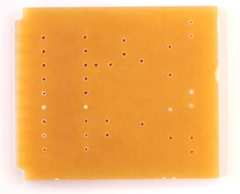
But it’s ok, I just cleaned it using a scalpel.
Success
Here is the module, soldered and connected to my HelloBoard :
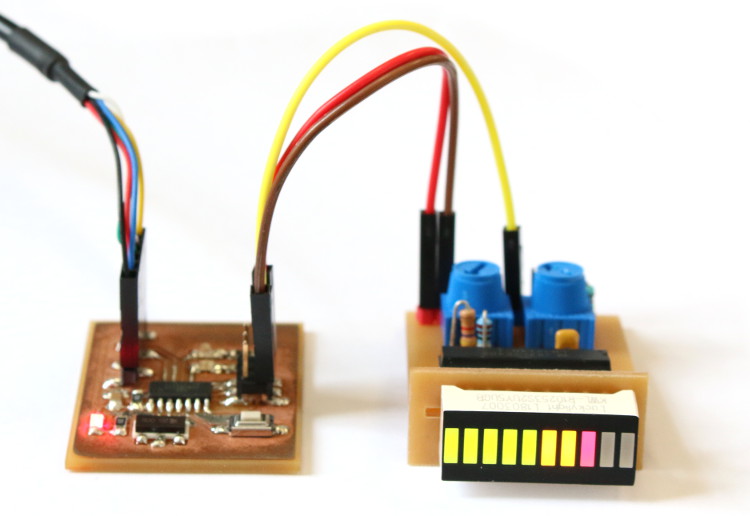
The HelloBoard is controlled from a computer, with a FTDI adapter.
Microcontroller interface
To control the bargraph module with my HelloBoard, I wrote a code to make the ATtiny84 read a byte from the serial port input and use it’s value to set the duty cycle of a PWM output.
The default PWM frequency is quite low and I had to use an analog filter to make it readable for the LM3914. So I tried to increase the PWM frequency to remove the need of an additional filter.
This is the code that I used for week 16 assignment an it’s archived in hello.ftdi.pwm.zip.
CAD files
Bargraph module EAGLE schematic and board