Idea & Development
Final Project
Here you can find a description of my final project, from the idea to the prototype and how I built everything. Have fun reading!
Searching for an idea
Weeks before the Fab Academy started, I was already thinking intensively about my final project. I had many conversations about it and looked through the Internet in search of an exciting topic and project with major potential.
I had several requirements for my final project. On the one hand I had a strong focus on 3D printing in combination with 3D scanning, which can result in individualized products with added value. I really wanted to choose a project, which can be individual manufactured, but I didn’t want to develop shoes or glasses, so I continued to look for opportunities for customised products in the area of application for 3D printing. On the other hand the project should also include electronic components. I wanted to work on a project, which offers a potential for the integration of artificial intelligence, but also has an influence on me, ideally on my health.
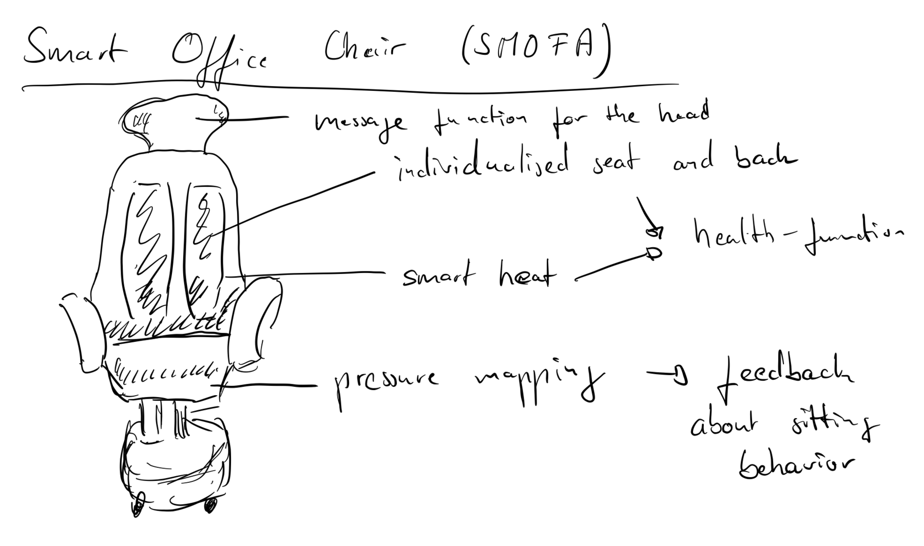
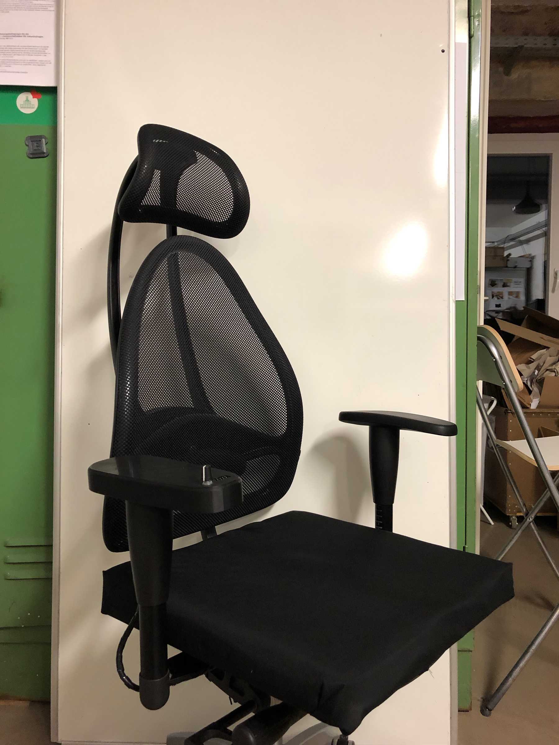
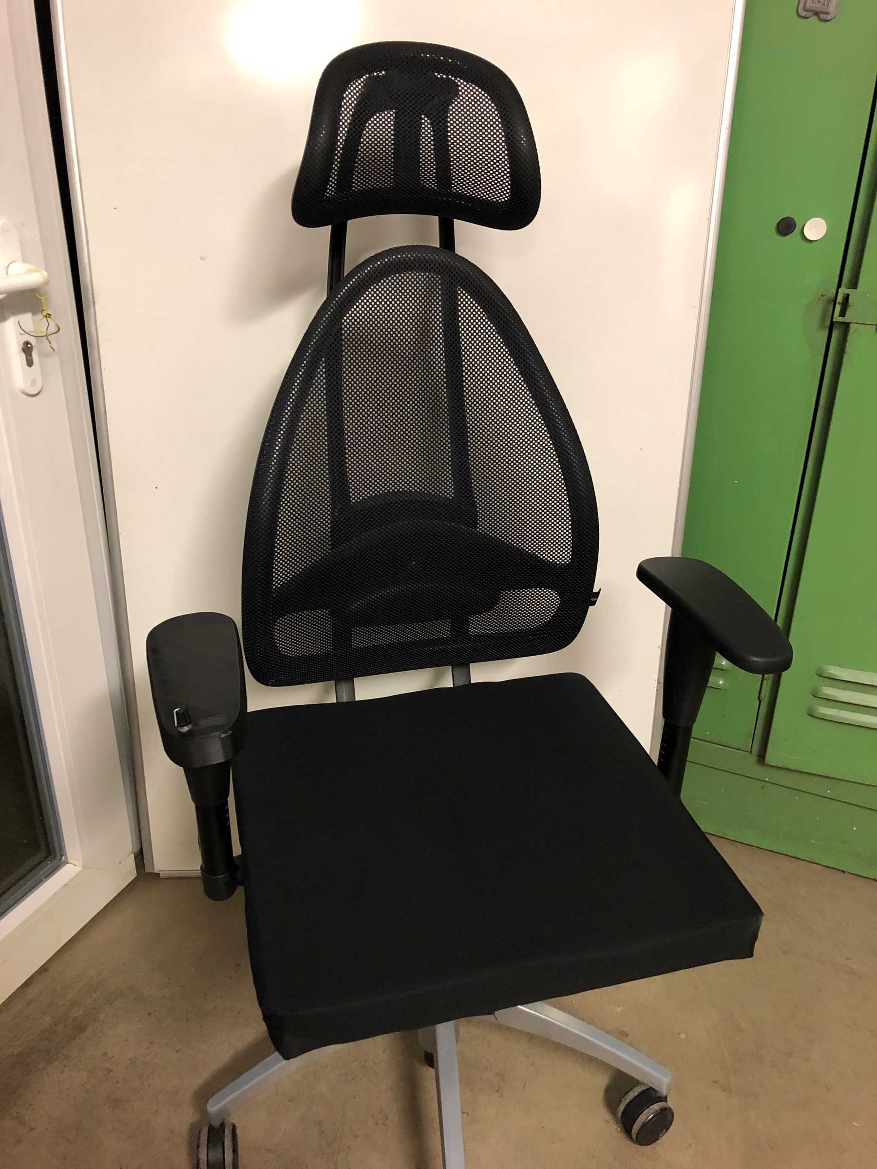
One week before the Fab Academy the idea came finally up: The smart and individualized office chair
My first drawing
Specify the idea
What will it do?
I want to optimize my daily work and this also includes the topic of sitting. Some days I sit on an office chair for more than 12 hours, a lot of time on a not so comfortable chair. If you extrapolate that, we spend 230 working days a year on one chair in a 5-day week after subtracting vacation and holidays. If we have a job that requires it. That’s the equivalent of 1840 hours, which is quite a lot. In this context, the office chair is an important everyday object which is used intensively and which, despite the digital age, is still analogue and thus harbours an undeveloped potential. So my goal is to build a smart and individualized chair as my final project.
I would like to address two key aspects here: On the one hand, new digital manufacturing technologies such as 3D printing and 3D scanning make it possible to create individually adapted seats and products. This makes it possible to distribute pressure forces in a balanced way and to avoid pressure points.
If you think about the whole topic around 3D scanning and 3D printing, you are quickly faced with the thought experiment of changes regarding new value chains through local and low-emission production. Social added value through the combination of local production and direct end customer feedback on the product through individualisation promise to create a positive synergy effect that underlines the sustainability and relevance of the issue.
On the other hand, the world is becoming more digital and networked. The so-called Internet of Things must be seen as an opportunity that can support our perception, information reception and processing. It can support us in our everyday lives and make recommendations for action, thus in the form of Extended Intelligence. Pressure sensors should record the sitting behaviour and generate measured values which are later converted into patterns. I would also like to integrate the pomodoro technique directly into my chair and give feedback via vibration motors. An OLED display should show the counter.
Who’s done what beforehand?
In the Fab Academy there have already been many projects with different ideas. After I had my idea and a few weeks passed, I could still find similar projects. Two people have already got to work on the chair. Nevertheless, I did not find anyone who addressed the topic of individualization and pressure mapping as I intended.
What will you design?
I don’t want to redesign the whole chair. I would rather focus on the seat and the other additional functions. These include the fitted seat, the housing of electronics, the implementation of the pressure sensors and the integration of the display into the armrest.
What materials and components will be used?
As materials I will probably use PLA or ABS as well as conductive filament based on PLA. Additionally acrylic or poplar wood is needed. Fabric for the seat as well as foam for a light upholstery.
Where will come from?
Most components, materials, etc. are already on site. Everything else is either ordered via Mouser (delivery within two days) or purchased locally from the dealer. The fabric as well as the foam are bought locally at the specialized trade.
How much will they cost?
| Name | Price |
|---|---|
| PLA Filament | 3 x 19,99 € |
| Conductive Filament | 68,90 € |
| Acrylic glass & Poplar wood | 12,00 € |
| Electronics like ESP32 Wroom, sd-card reader, OLED-display, resistors and so on | 15,00 € |
| Textiles | 4,00 € |
| Total | 159,87 € |
What parts and systems will be made?
Both the seat and the electronics themselves are designed. I also design the implementation of the pressure mapping system, the integration of the pomodoro technique and the control itself.
What processes will be used?
2D and 3D design, additive and subtractive manufacturing processes, electronics design and production, embedded microcontrollers, interface and programming, system integration and packaging are used. That’s very probably the technology used:
- 3D-Scanner
- 3D-Printer
- Laser cutter
- Vinyl cutter
- PCB-milling machine
- embroidery machine
- CAD-Software
- Programming
What questions need to be answered?
- How can I implement pressure mapping and determine whether a person is sitting or not?
- How do I ideally integrate the pomodoro technique?
- How do I implement the haptic feedback system?
- How can I create a seat from the scan?
Further questions that came to my mind and which I would like to clarify for myself after the project:
- Does an individualised office chair really bring added value?
- Are the functions accepted by the user?
- Is an integrated massage function really good?
- Is the pomodoro technqiue integration in a chair more effective than the use of an app?
- Which information can actually be read via Pressure Mapping? According to studies, data ranging from emotional state to emotions can be detected. Can I really do that?
- Have I achieved reflected behaviour with this office chair and actually optimised my everyday life?
Intellectual Property
The topic of individualization, especially in combination with the new digital manufacturing technologies, is still in its early stages. There are only a few end customer products. Disruptive innovations are rare. Value chains only change slowly because many product requirements have not yet been fulfilled. At the Fab Academy I also learned a lot about how important it is to find the right workflow at all stages. The use of 3D scans and the subsequent editing, ideally parameterized, is not as trivial as you might imagine. That’s why I see potential for further research and development here.
I would like to continue to use the chair as an example for my research. The sitting behaviour is completely different from that of an unadapted chair - at least after my first observation. I’m particularly interested in how you can continue working with the scan data later. How do others do it? It’s not like an orthosis, where you extrude a body on the scan. Rhino would be a possibility that I would like to pursue in the next few months. Especially the use with Grasshoper sounds promising. Further a mathematical adjustment, the evaluation of a heat map or something similar would be possible.
After a certain amount of preliminary work, I would like to start a research project on the subject. How can individualised products be produced locally in the city? What do future and possible value chains look like? There are several chair companies that are not yet active in this direction. Cooperation would be possible here, which I would welcome.
In addition to the relevant topic of individualization, the topic of pressure mapping and the associated data analysis is very exciting for me. I see a lot of potential here for the application of machine learning and would like to deepen this. For me, this would be an excellent example of an application that I would very much like to work on.
In a way, I see many research topics in the entire final project that I would like to investigate with partners. Later, after many iterations, a product would also be conceivable.
In the context of the Fab Academy I make all my developed contents available with the following license model:

This work is licensed under a Creative Commons Attribution-NonCommercial-ShareAlike 4.0 International License.
That means that you’re free with regard to
- Share — copy and redistribute the material in any medium or format
- Adapt — remix, transform, and build upon the material
But under the following terms:
- Attribution — You must give appropriate credit, provide a link to the license, and indicate if changes were made. You may do so in any reasonable manner, but not in any way that suggests the licensor endorses you or your use.
- NonCommercial — You may not use the material for commercial purposes.
-
ShareAlike — If you remix, transform, or build upon the material, you must distribute your contributions under the same license as the original.
- No additional restrictions — You may not apply legal terms or technological measures that legally restrict others from doing anything the license permits.
Final project plan
In the last week I finally had time to work only for my final project. A week of intensive vacation. Since I was still missing some things for my final project, I worked out a final plan and also clarified some questions for myself.
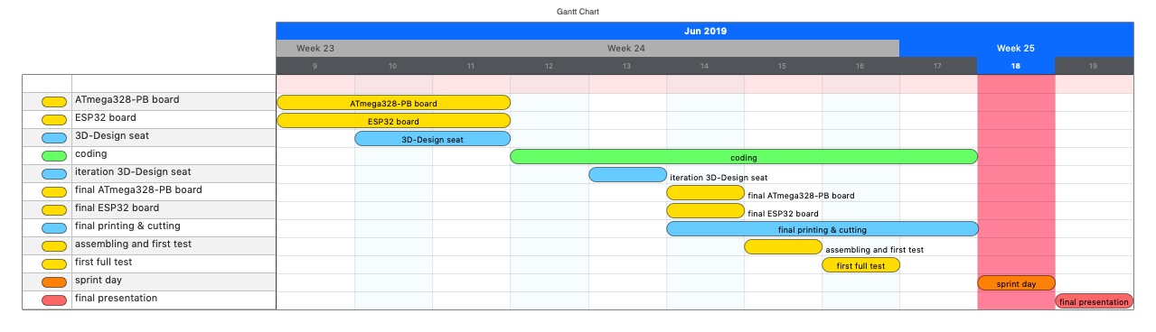
Intermediate conclusion: The whole thing had to be well coordinated because it will be a really tight challenge. Because of the amount of time I had and the few days I had left, I made a priority list. I deleted some features and concentrated on the basic functions. For an overview I always need a Gantt chart, which looked like the following for me:
3D-Design of the seat
Get the shape
A big challenge was the development of the workflow for the seat. How do I make a seat that is adapted? Simply scan, model something and print it out: it’s possible, isn’t it? No! it was an odyssey. It certainly wasn’t the best solution and Rhino could be an option for the future. But I’m not familiar with it yet, because I only bought the software a few weeks ago and didn’t have time to really get used to it. So: Autodesk Fusion, MeshLab, MeshMixer, Blender, etc. try out. But before I tell you about these steps, I’d rather start at the beginning, the shape and the scan:
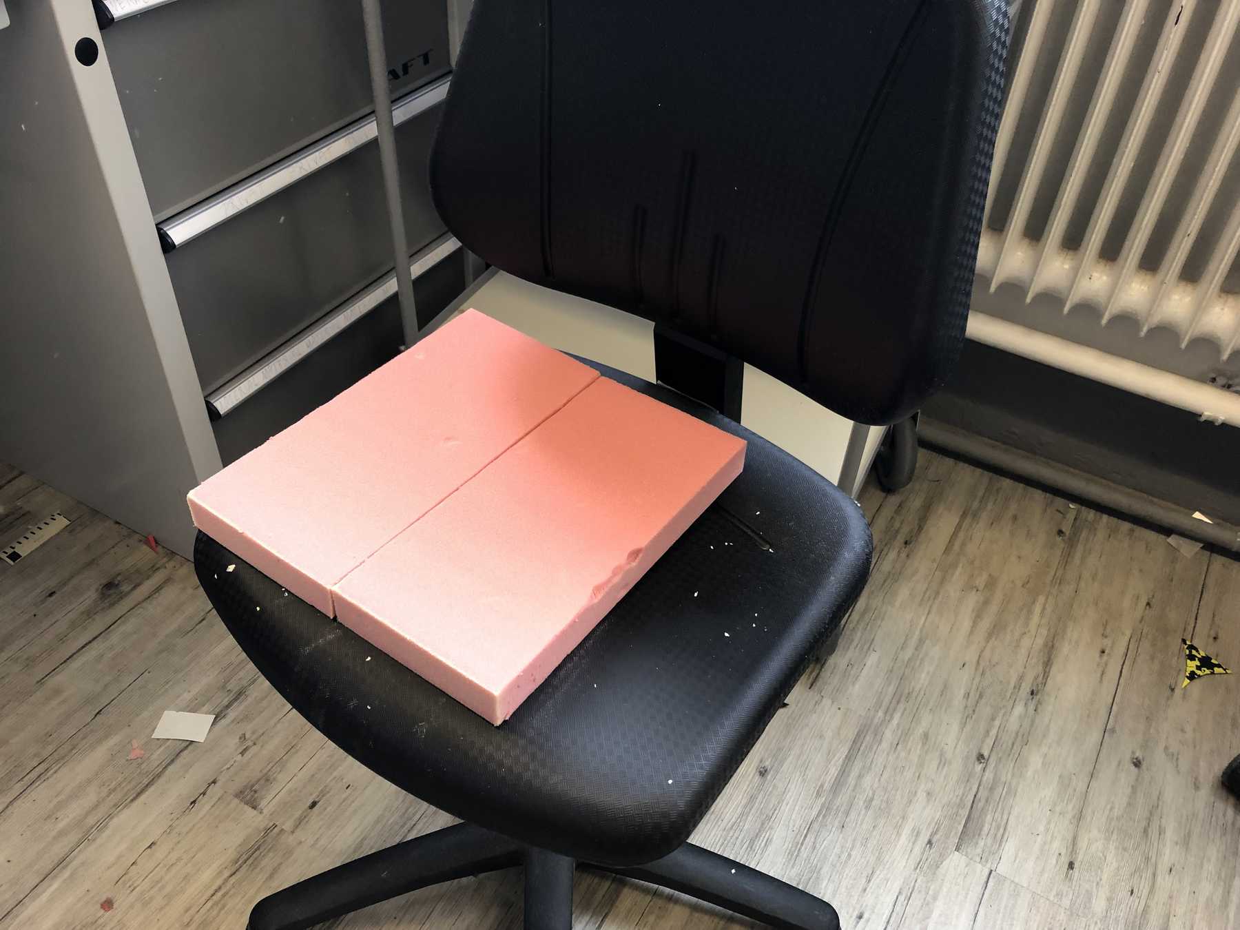
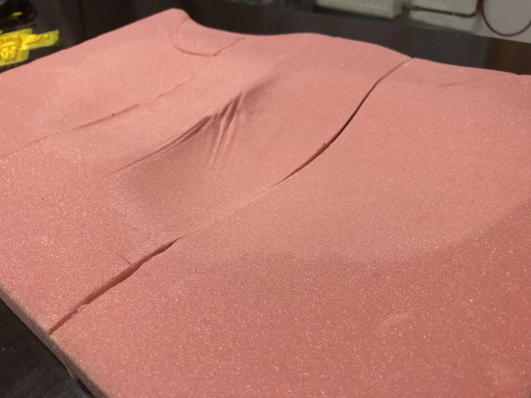
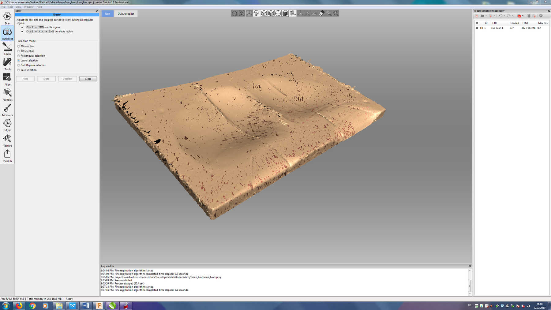
For this I already did in week 6 preliminary work. Thanks to our project partner Sanitätshaus Kraft, a medical and health care manufacturer and supplier, I was able to use footprint-foam, which is normally used for the foot. Here you create pressure on the footprint-foam by standing on it and get an exact result of your foot. Based on this, soles are usually produced. In my case we placed several of these footprint-foam next to each other and then I sat down on them. Now I have scanned this impression.
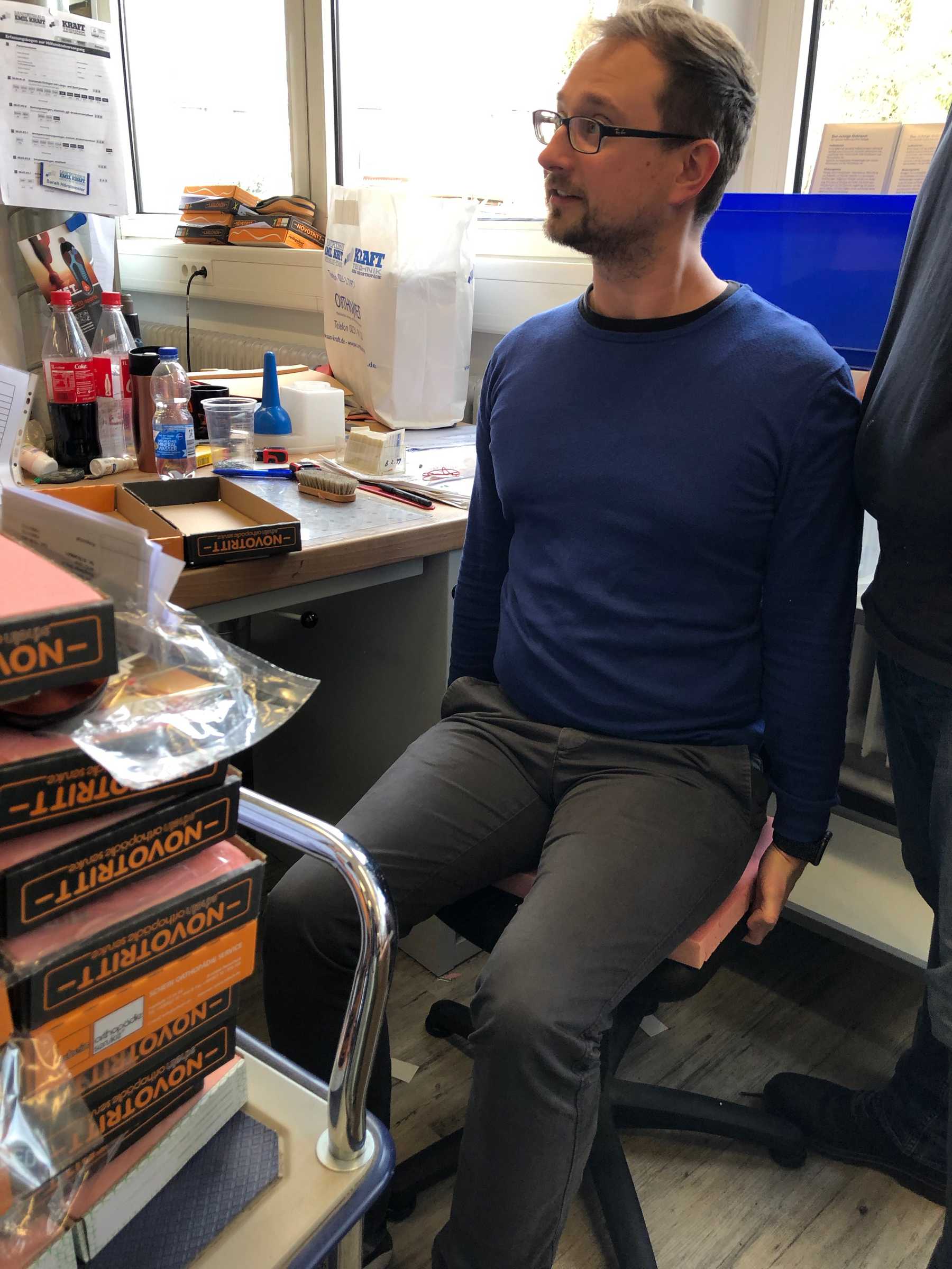

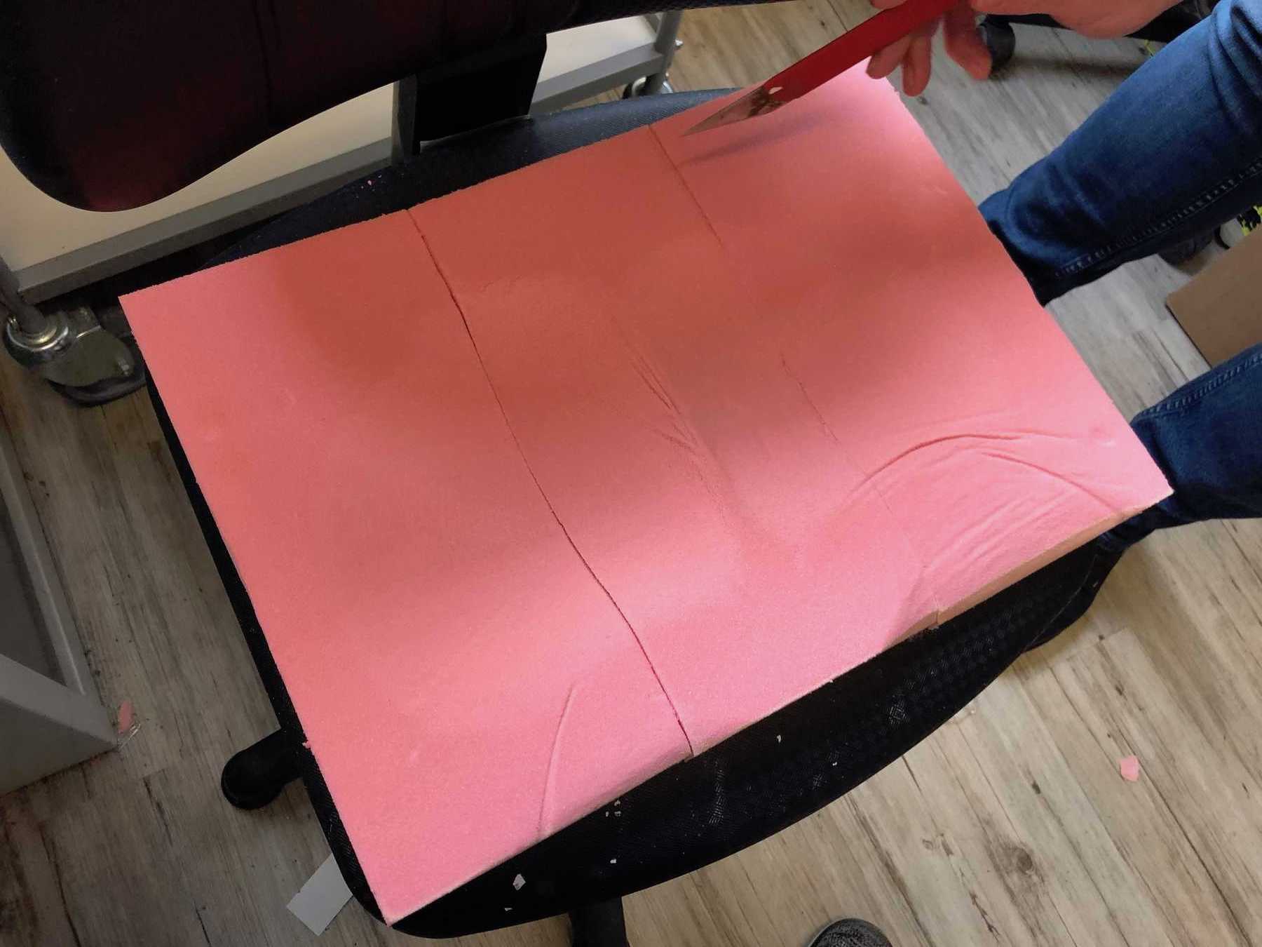
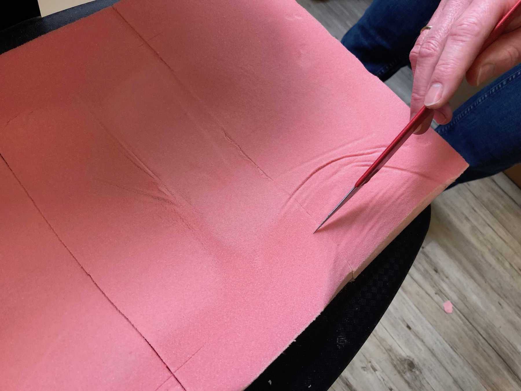
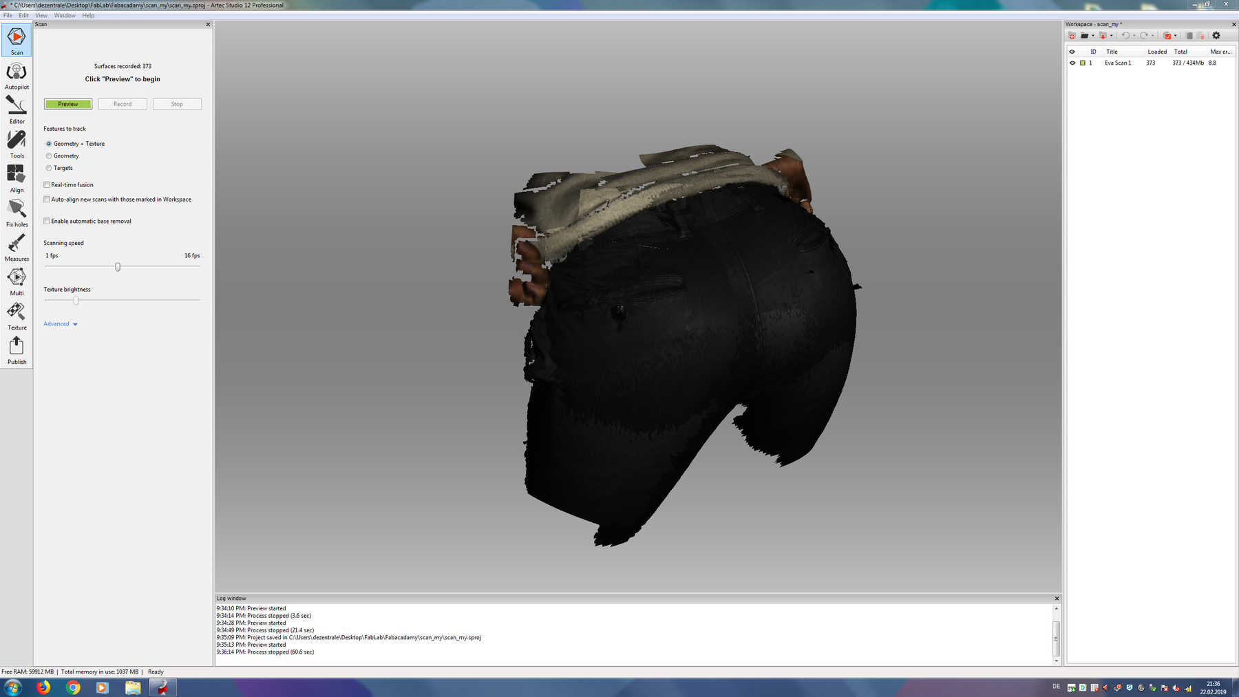
To generate a comparison of the direct scan of my backside and the scan of a result of my backside, I have tried both variants. But you could immediately see the differences, so I decided to continue working with the impression. Here the pressure distribution was much better visible.

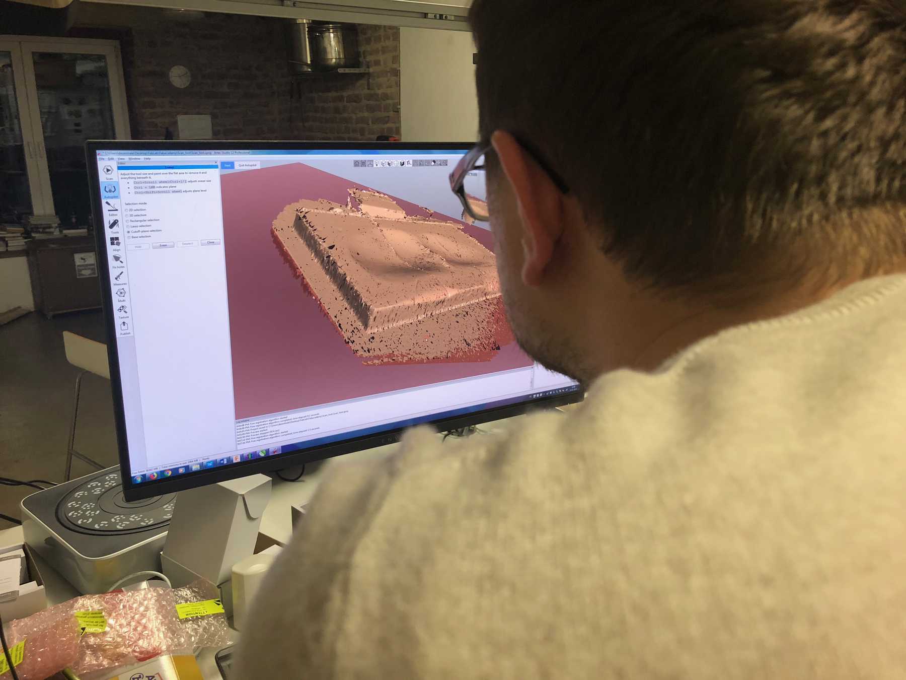
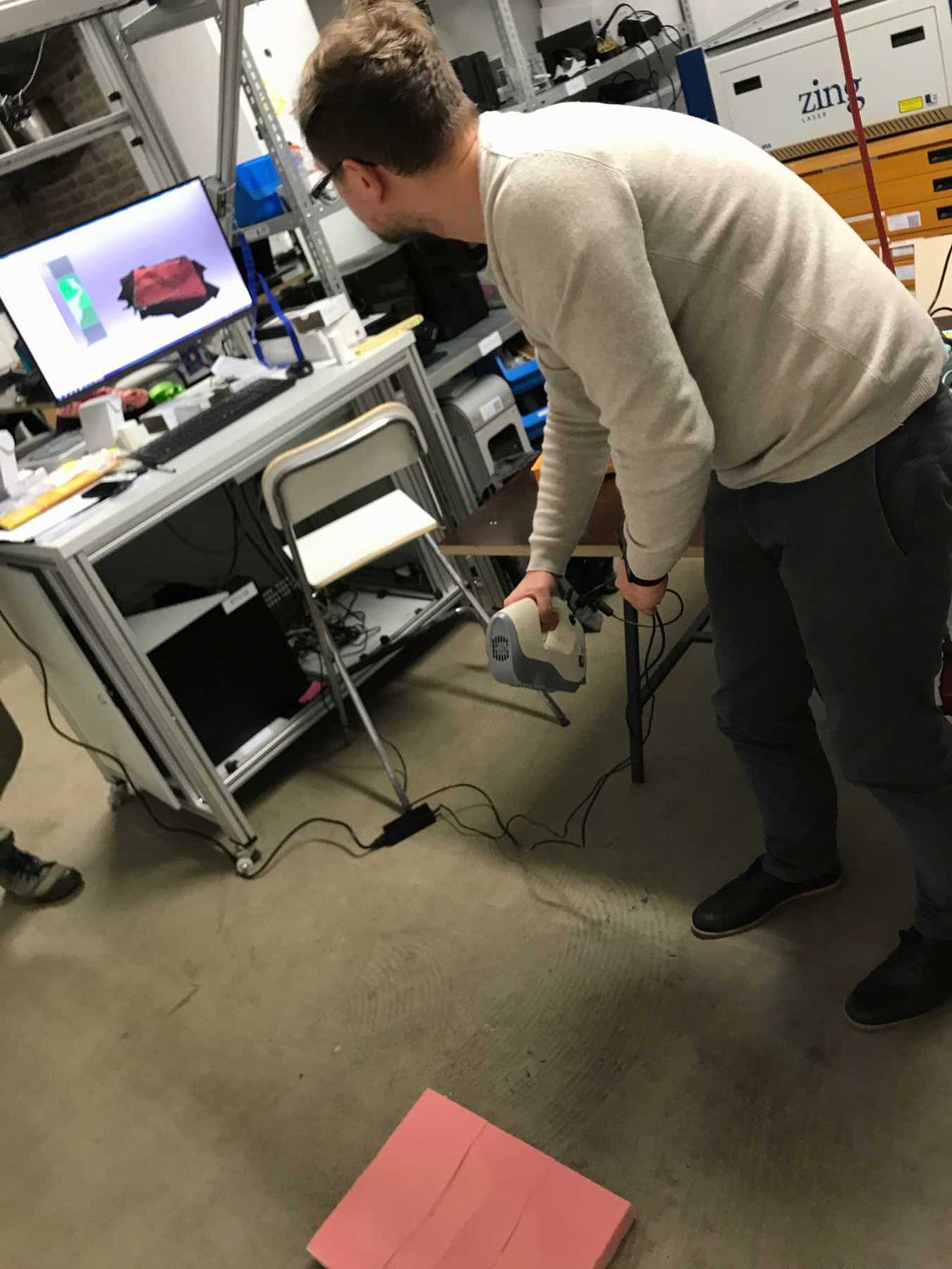
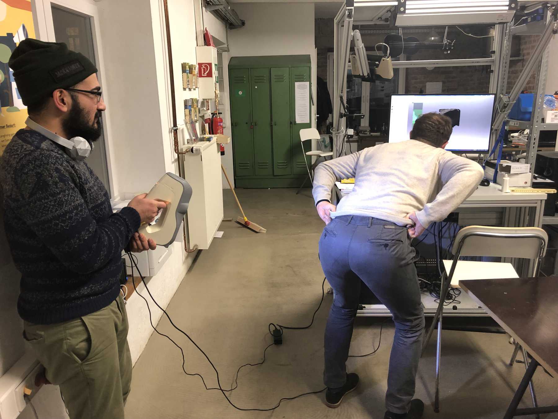
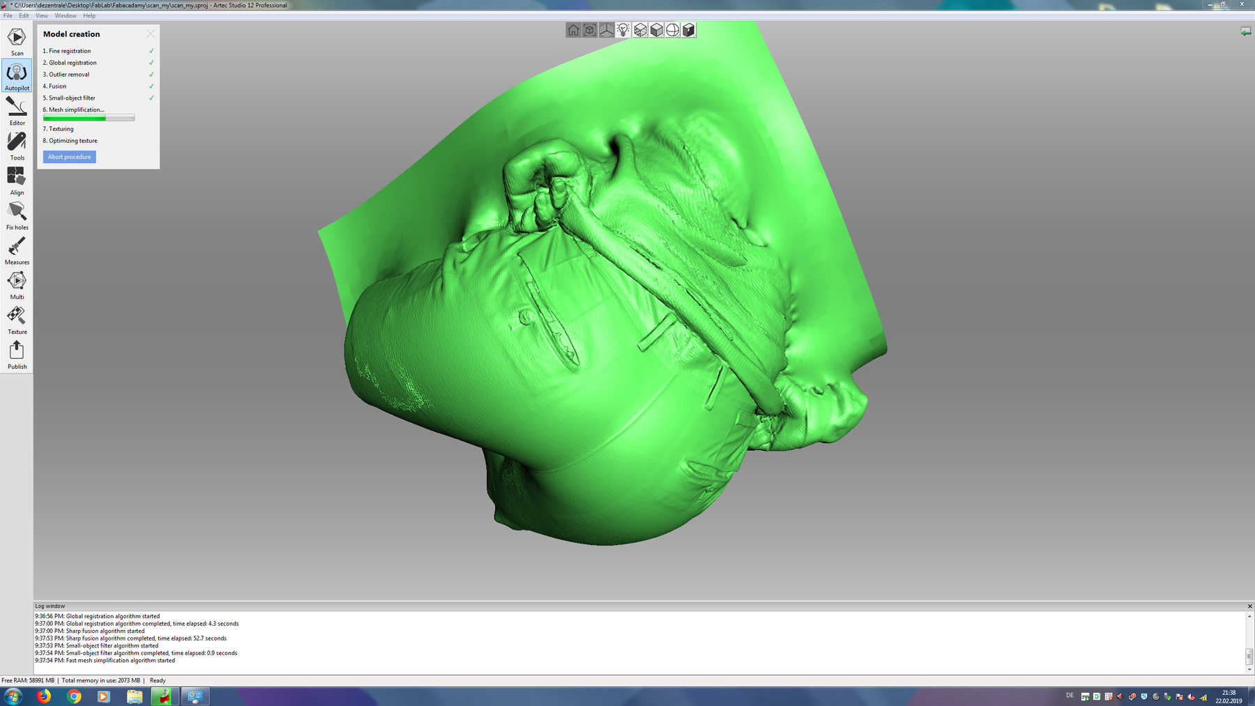
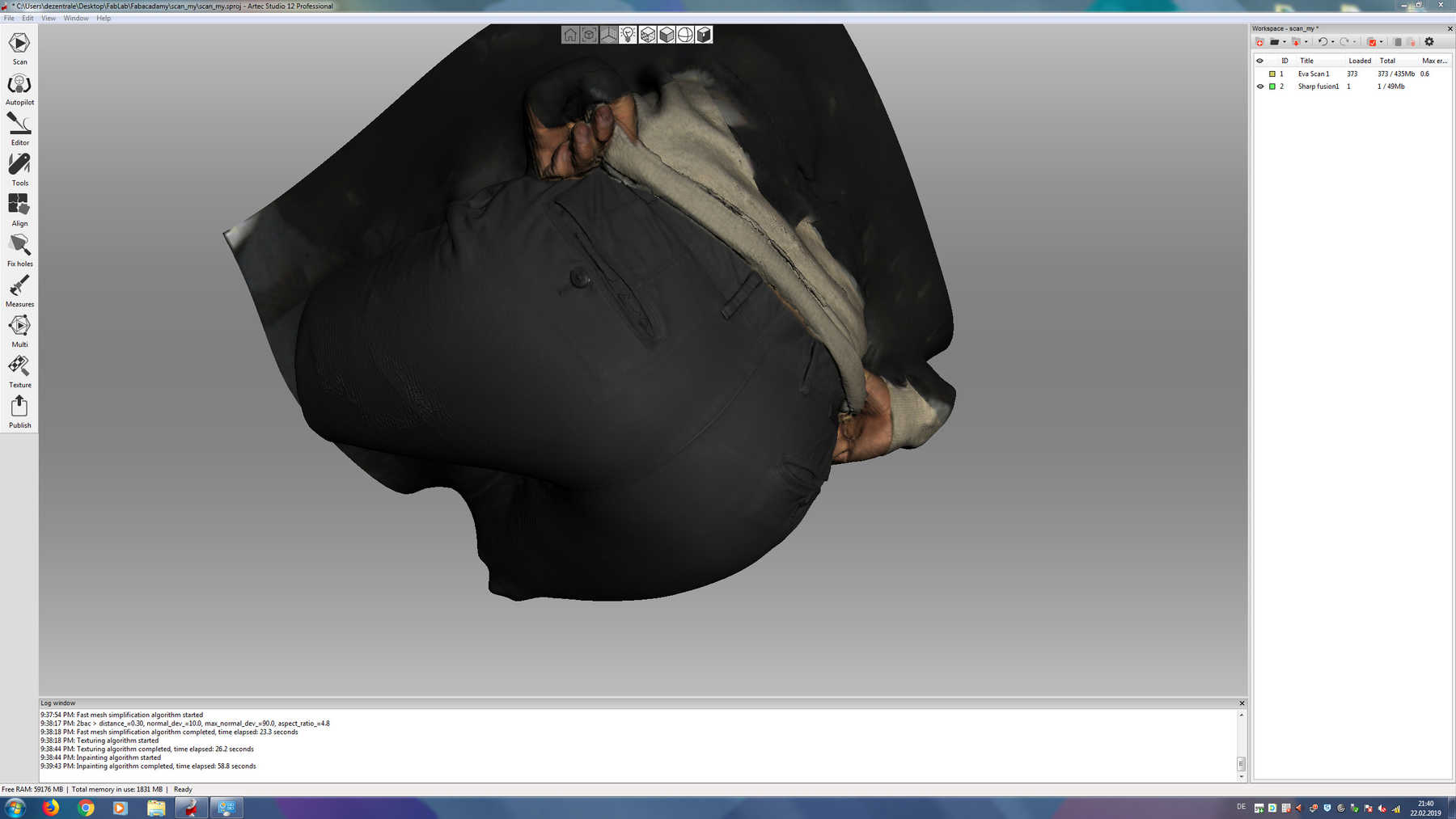
Somehow I got used to the 3D scanner from Artec. A device, where you have to look on the screen while scanning, because on the monitor lies the information about the distance measurement. A logical and meaningful operability was definitely not a high priority during the development of this scanner. Nevertheless, there is much magic in the software. Thanks to good algorithms, the software can perform some miracles from different scans. For small objects, we use the Artec Spider, for large objects like my butt I use the Artec Eva.
The used software is Artec Studio, which offers many possibilities. Primarily there are two ways, the use of the autopilot or an odyssey of click options. Both lead to relatively similar results. The following pictures show the way from 3D scanning, the different models that were scanned and the help I got.
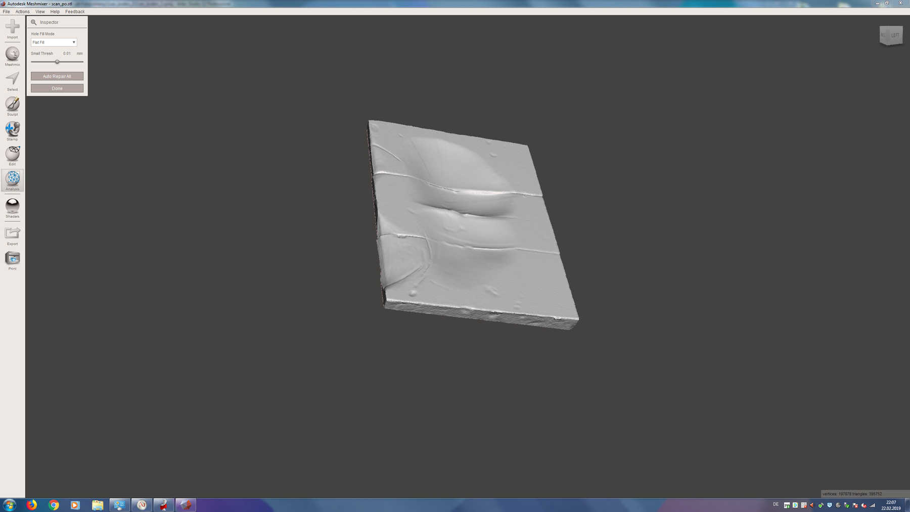
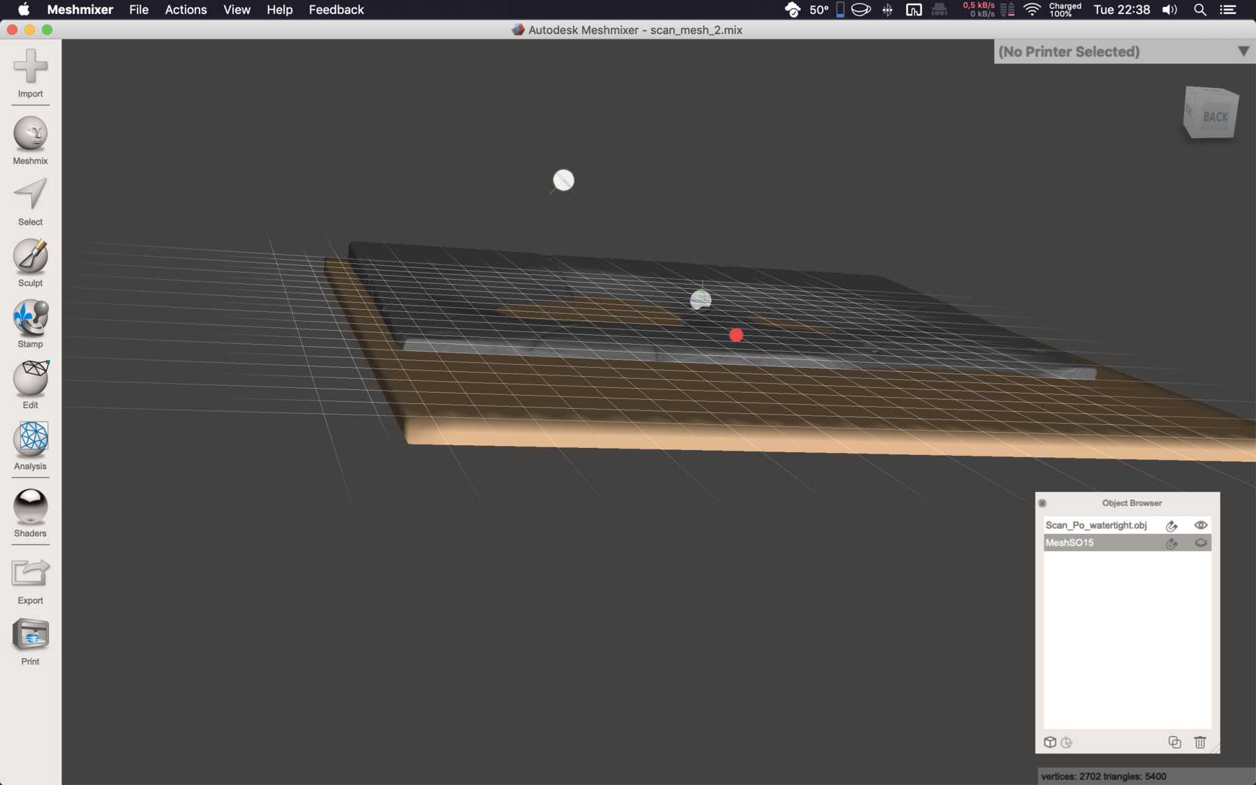
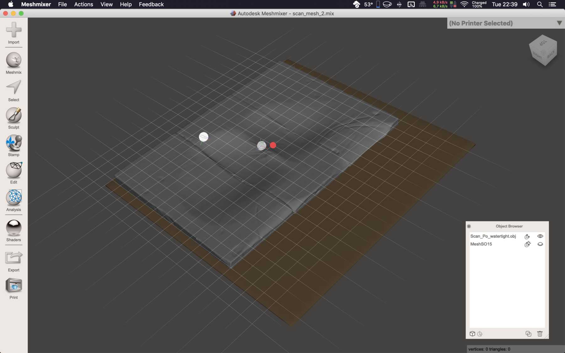
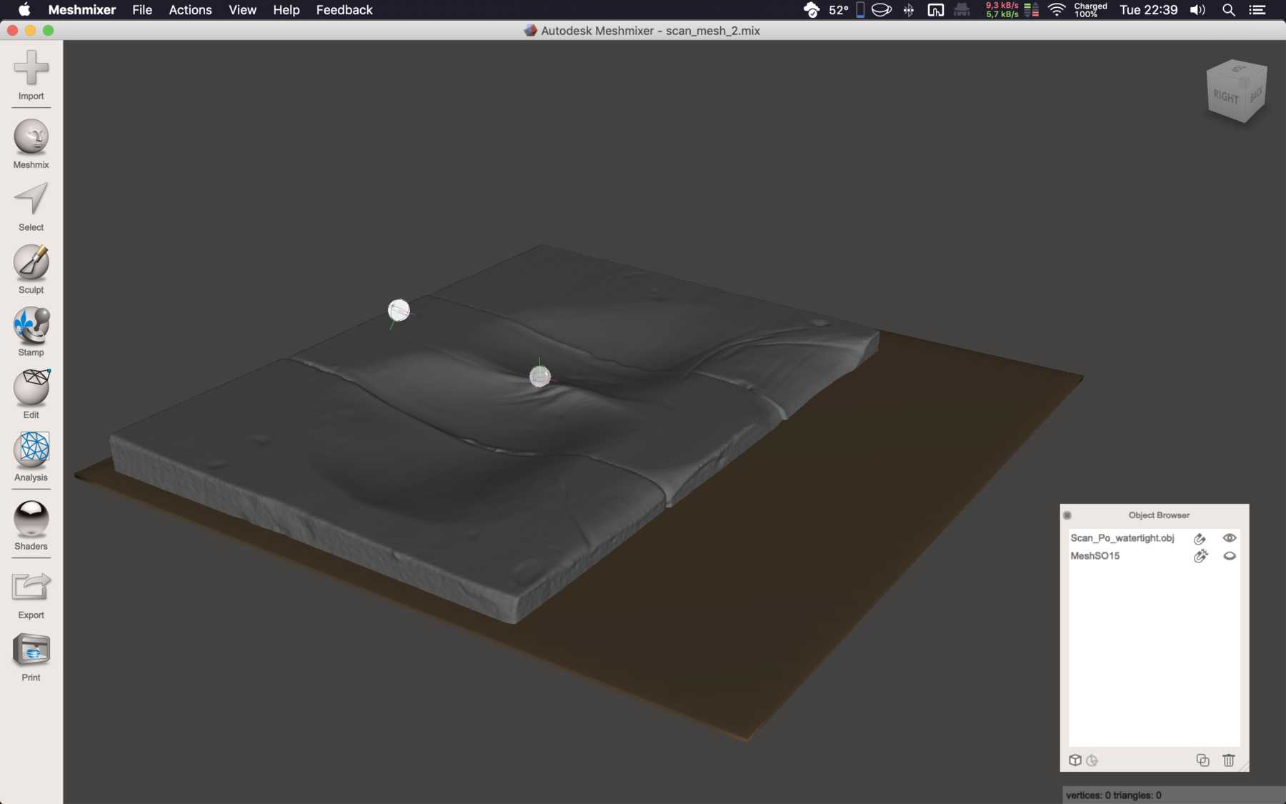
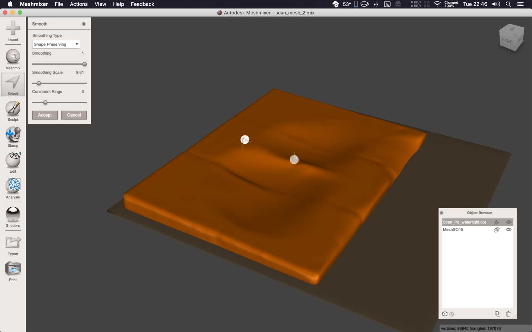
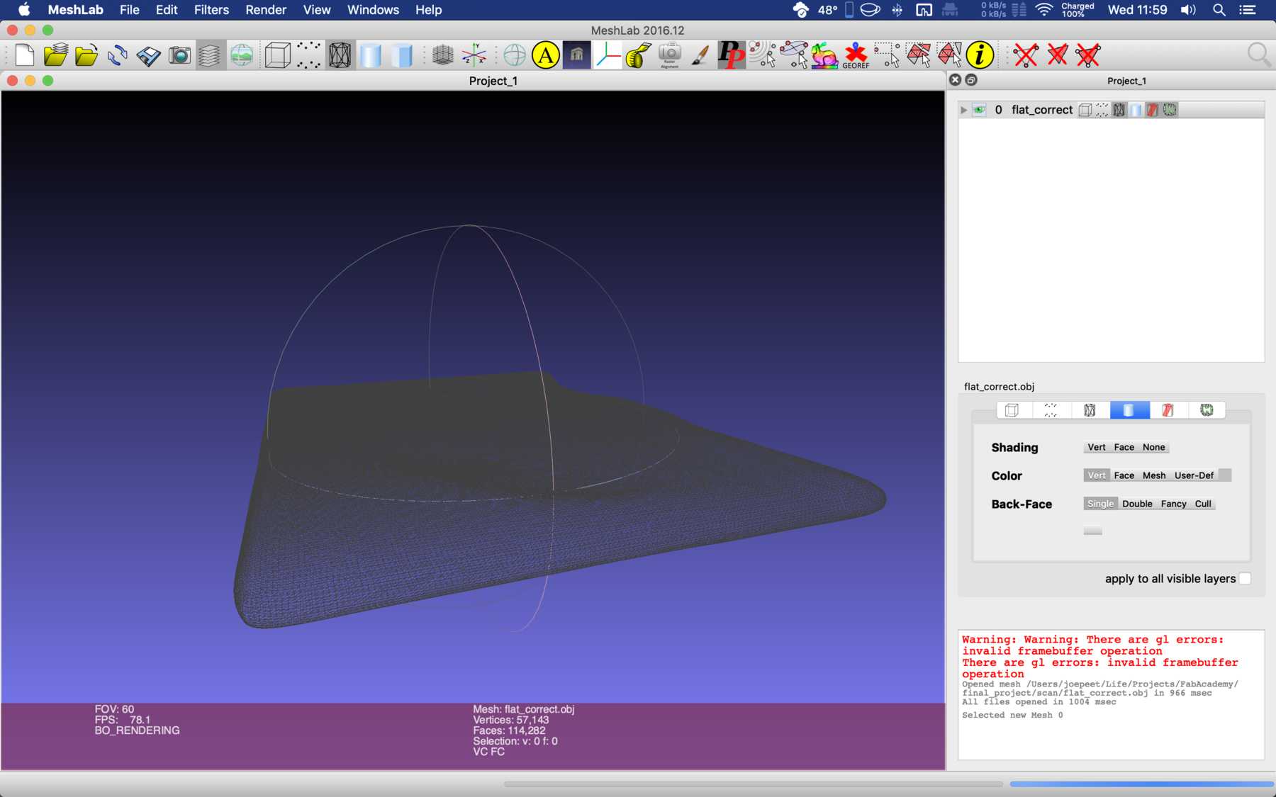
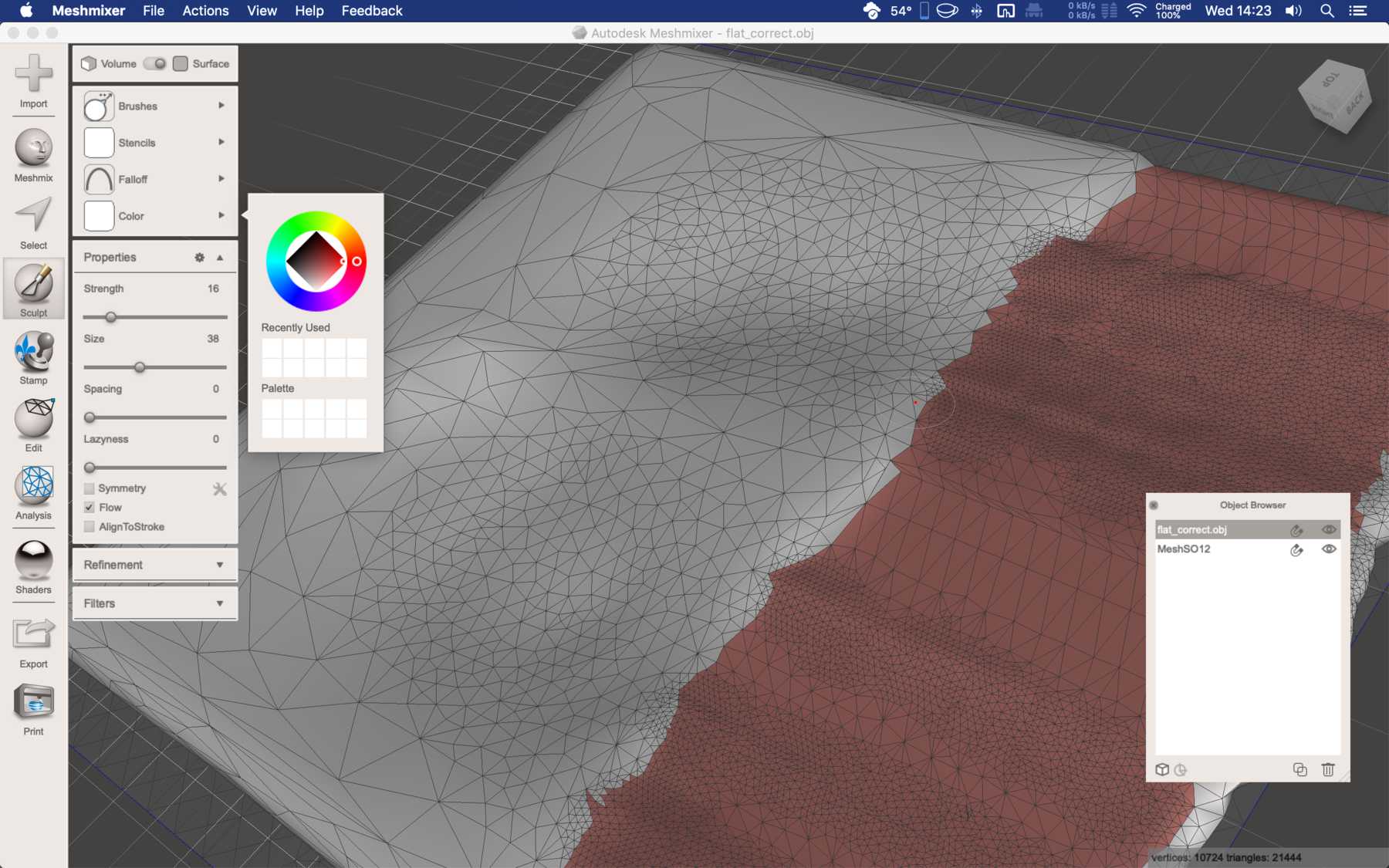
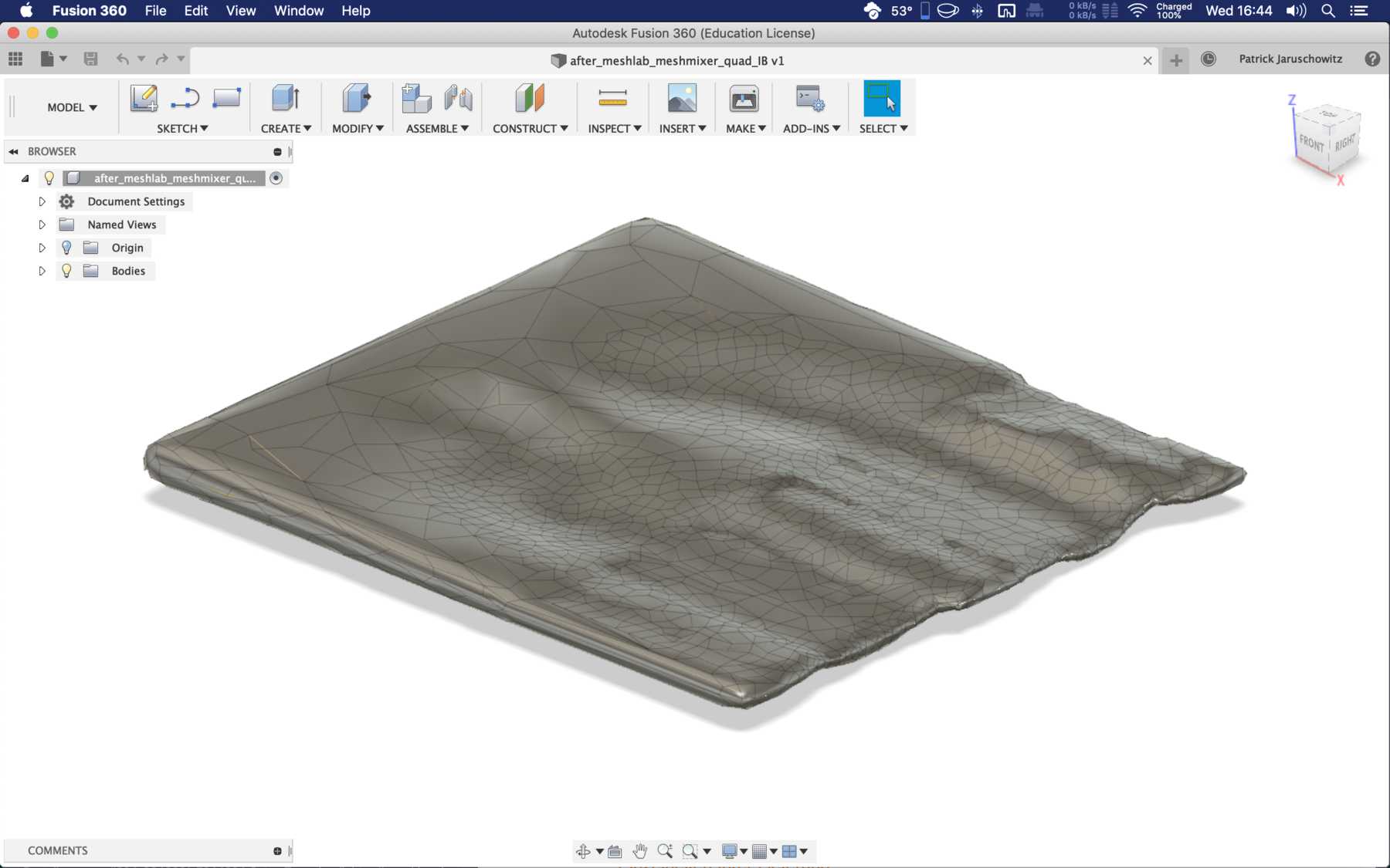
Fixing the model with meshmixer
Unfortunately, there were some difficulties with the one scan, so the water filling function did not give correct results. After several experiments I wanted to use the simpler variant, Meshmixer to correct the object. The following picture show the result.
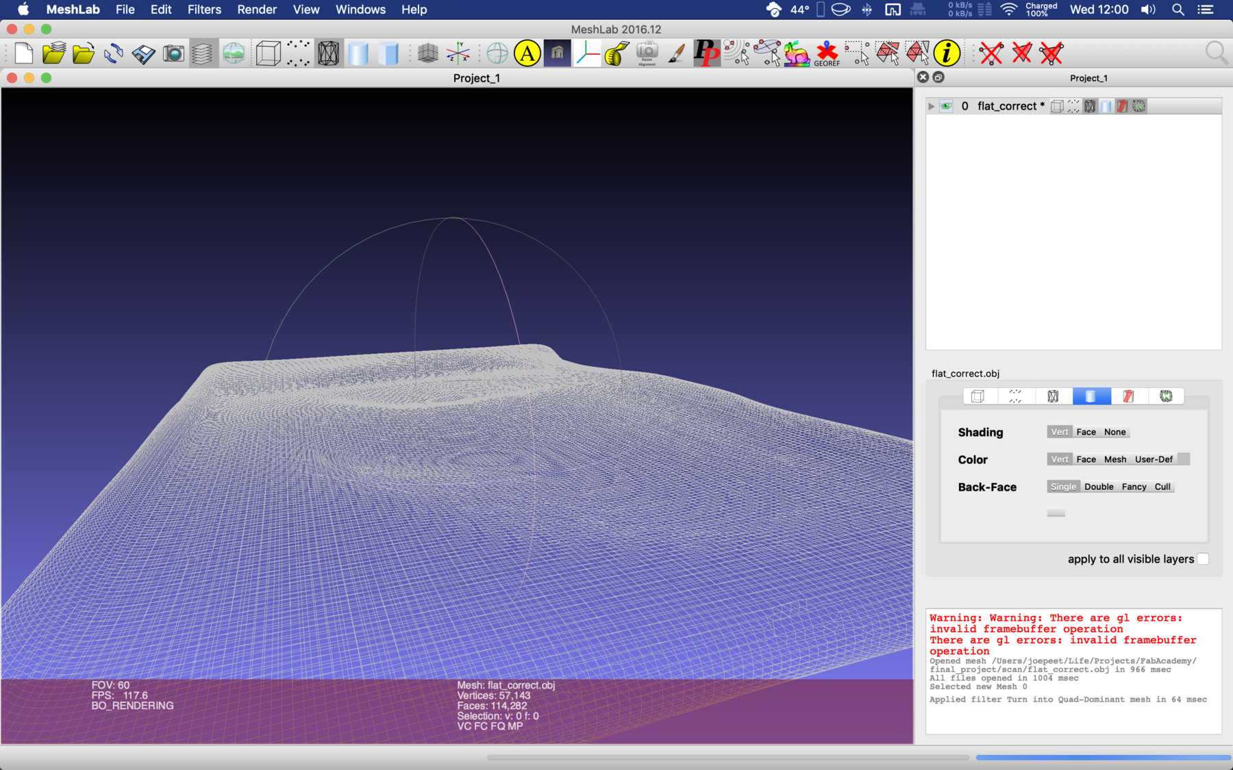
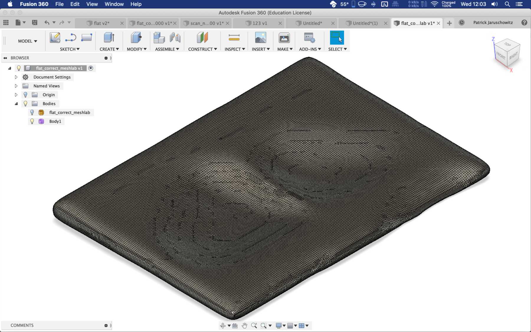
Working with mesh data
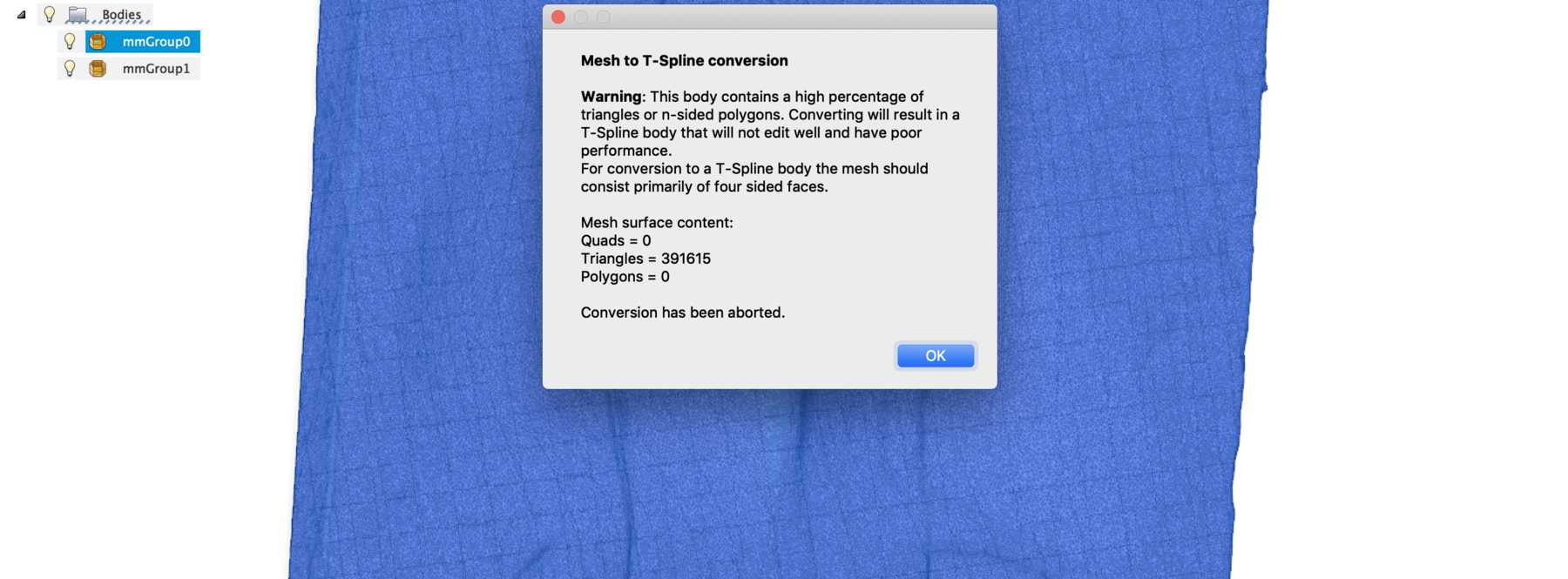
Now I had my scan. Excellent. But what else?
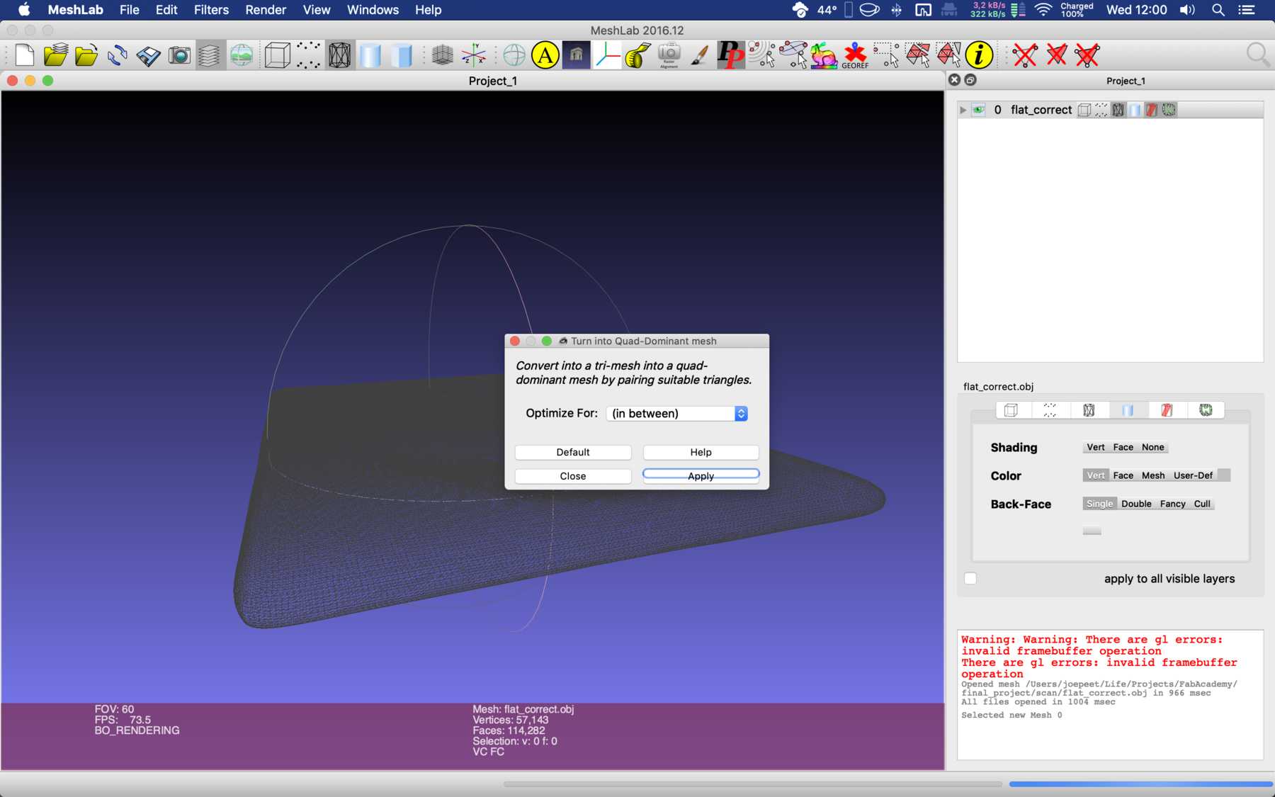
First I tried to work in Fusion, then in Meshmixer, then in Meshlab, from triangles to squares, so that Fusion accepts them. Then I noticed that the program doesn’t support the necessary functions anymore. Then back again. What about Blender? You could do a good job with that, couldn’t you? No, it didn’t look so good then. Constant problems with scaling - sometimes factor 1000, sometimes factor 4000. Why 4000? Oh, I don’t know. Here a few pictures of the Odyssey.

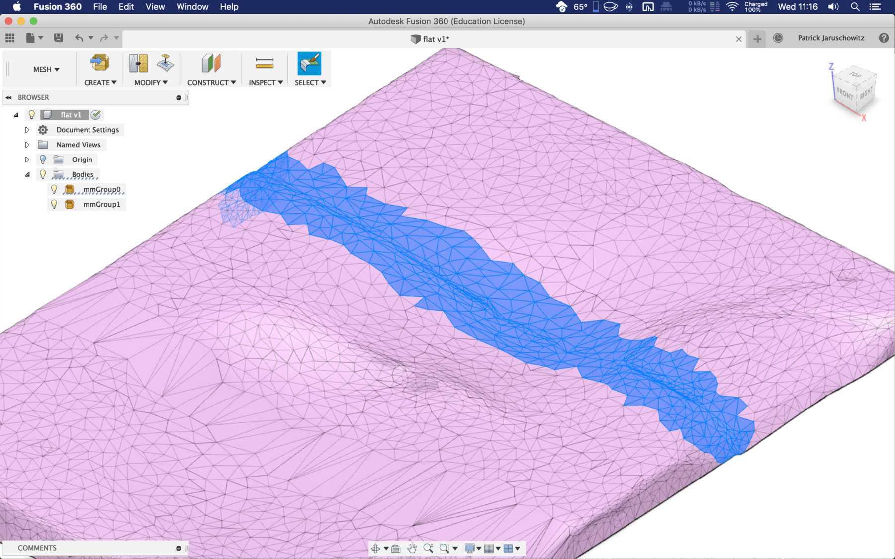

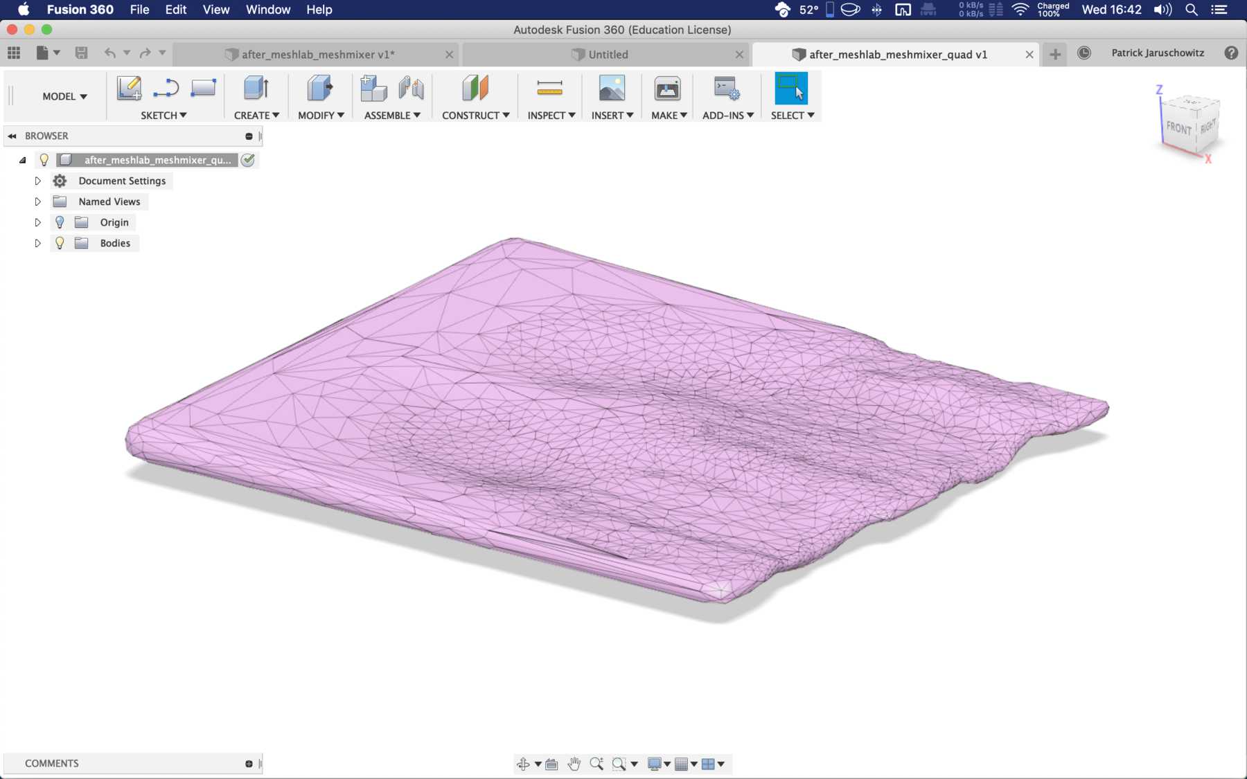
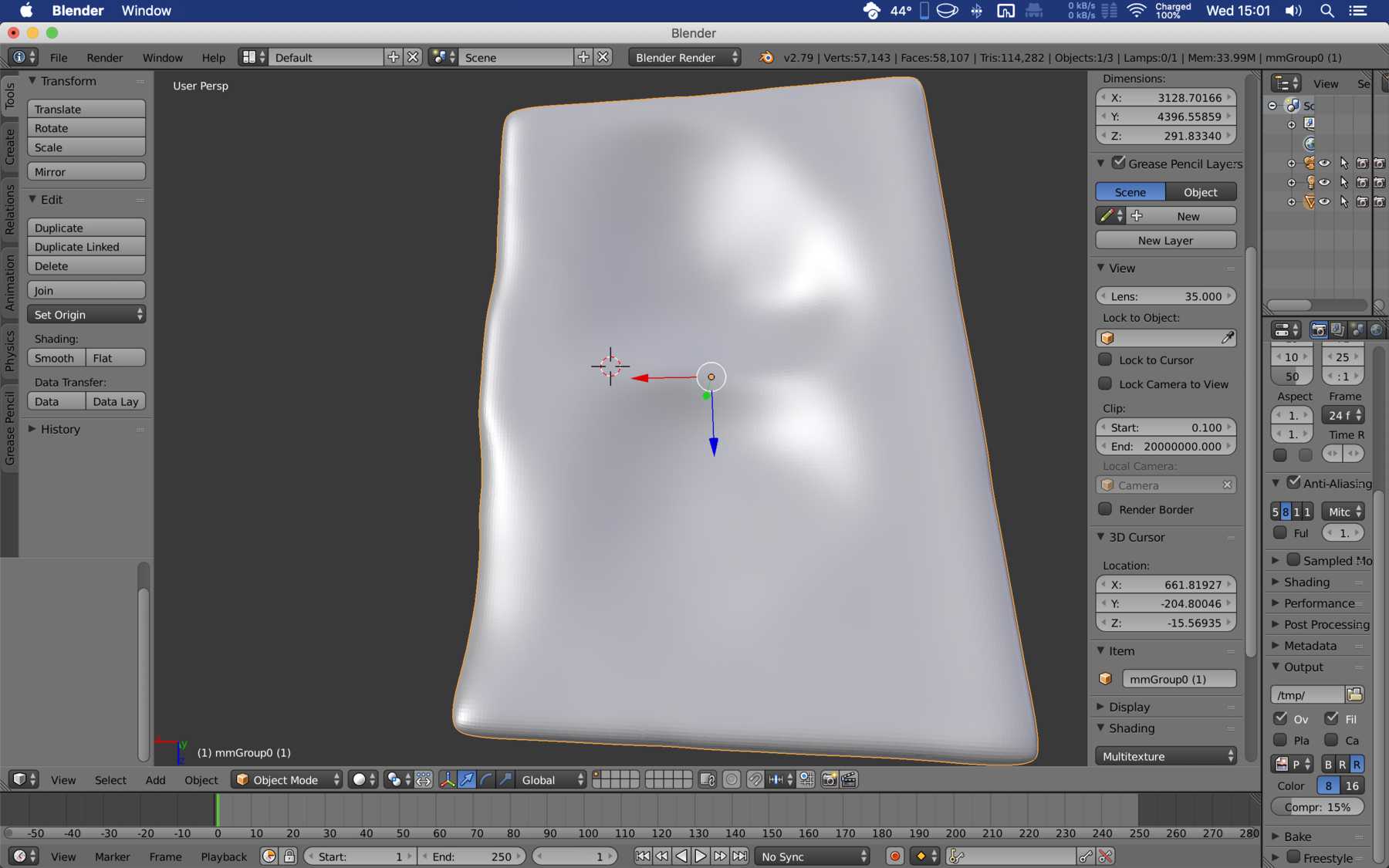
After a few hours and two days a friend finally had a good solution for me. It looked like this:
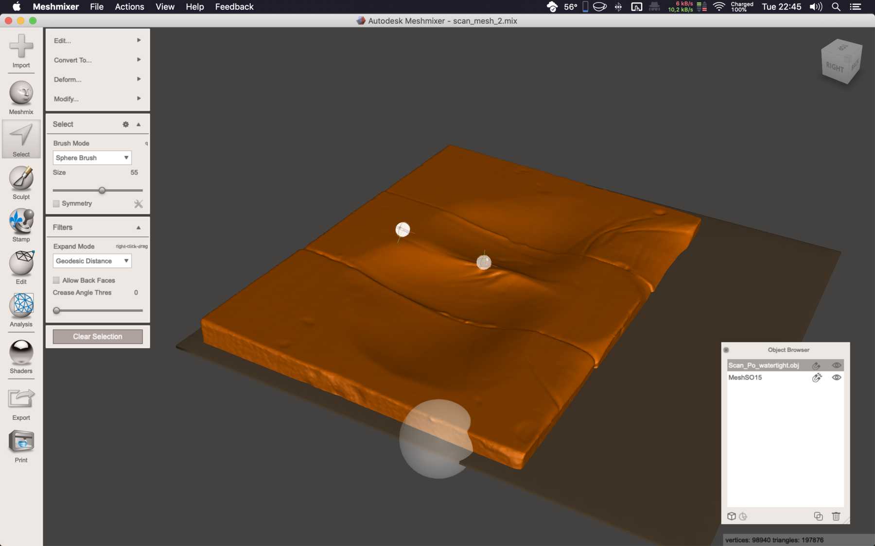
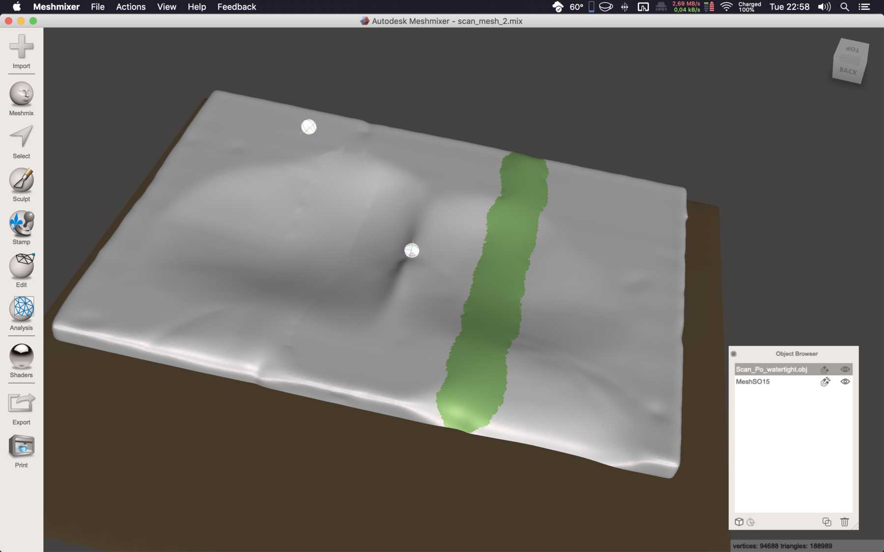
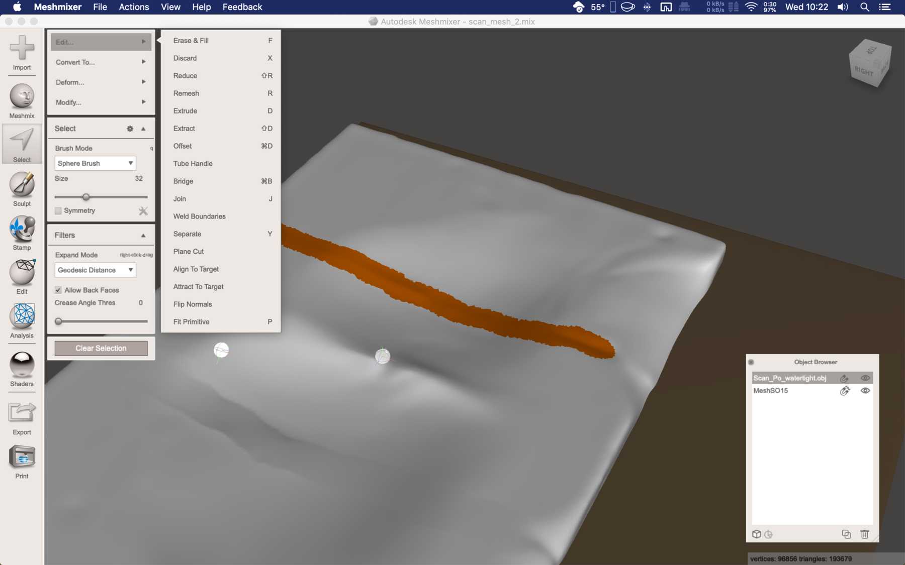
Take the scan and process it in Meshmixer:
- Select All
- Delete face group (one face group is easier to work with)
- Cut bottom + edges
- Smooth & delete uneven areas
- Remesh it
- And uniform
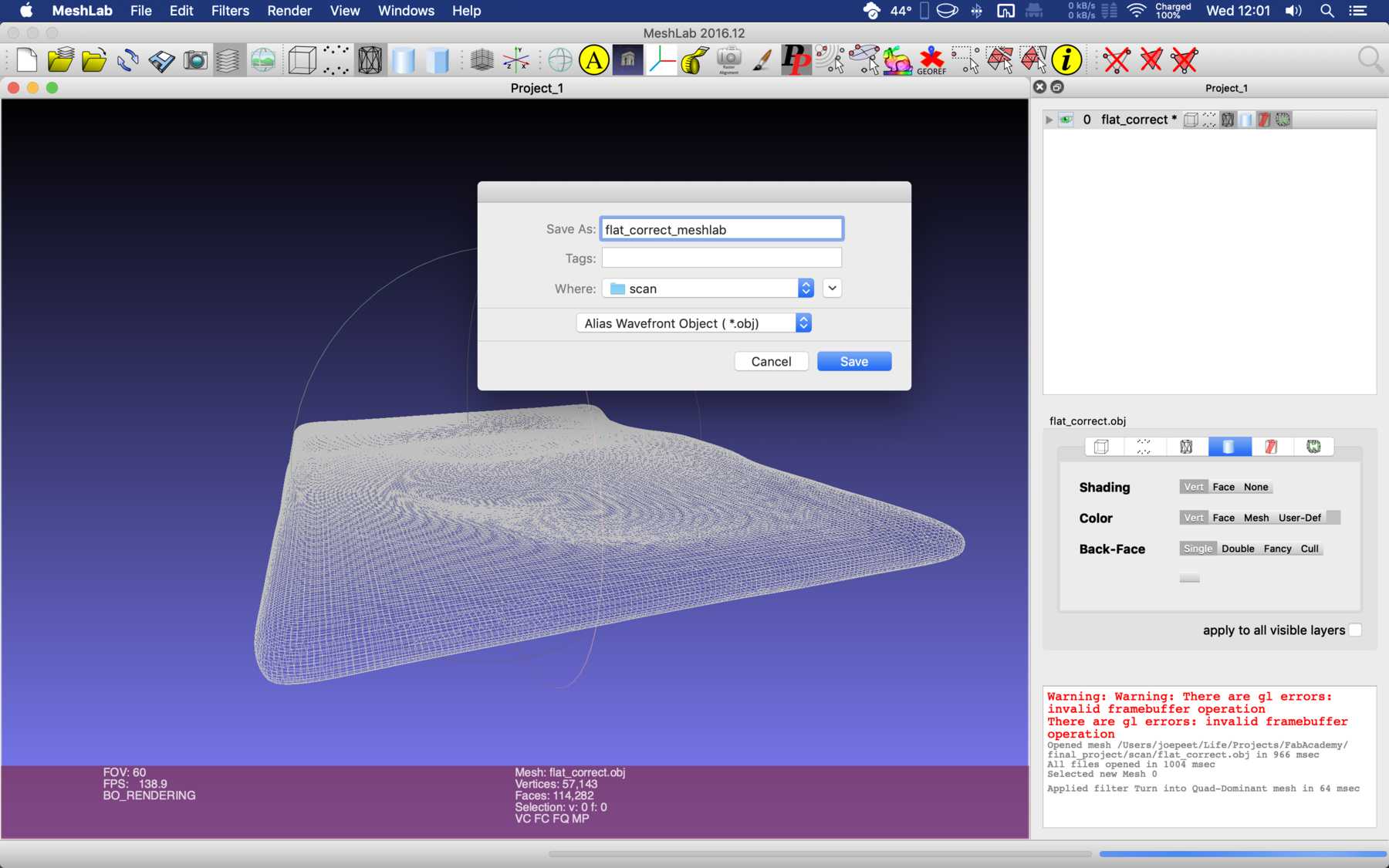
- Export the mesh as an *.stl.
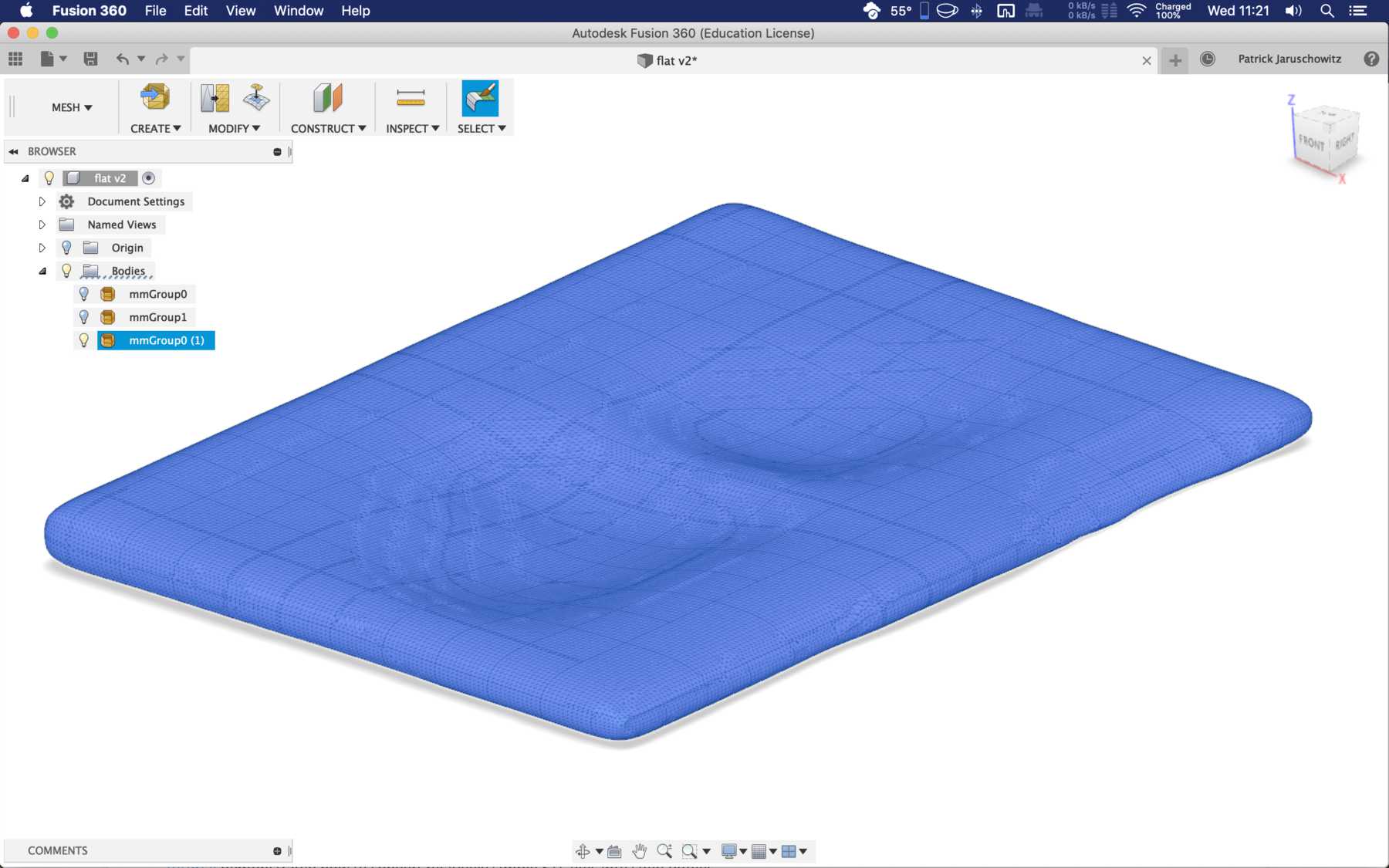
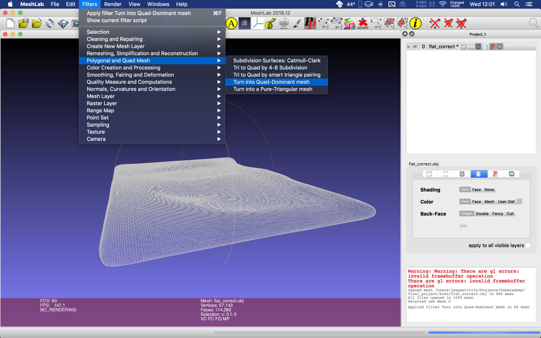
Import it to 3ds Max:
- Select all
- Convert into poly
- Quadrify all
- Export as *.FBX (attention: export settings - dimensions - coordinate system)
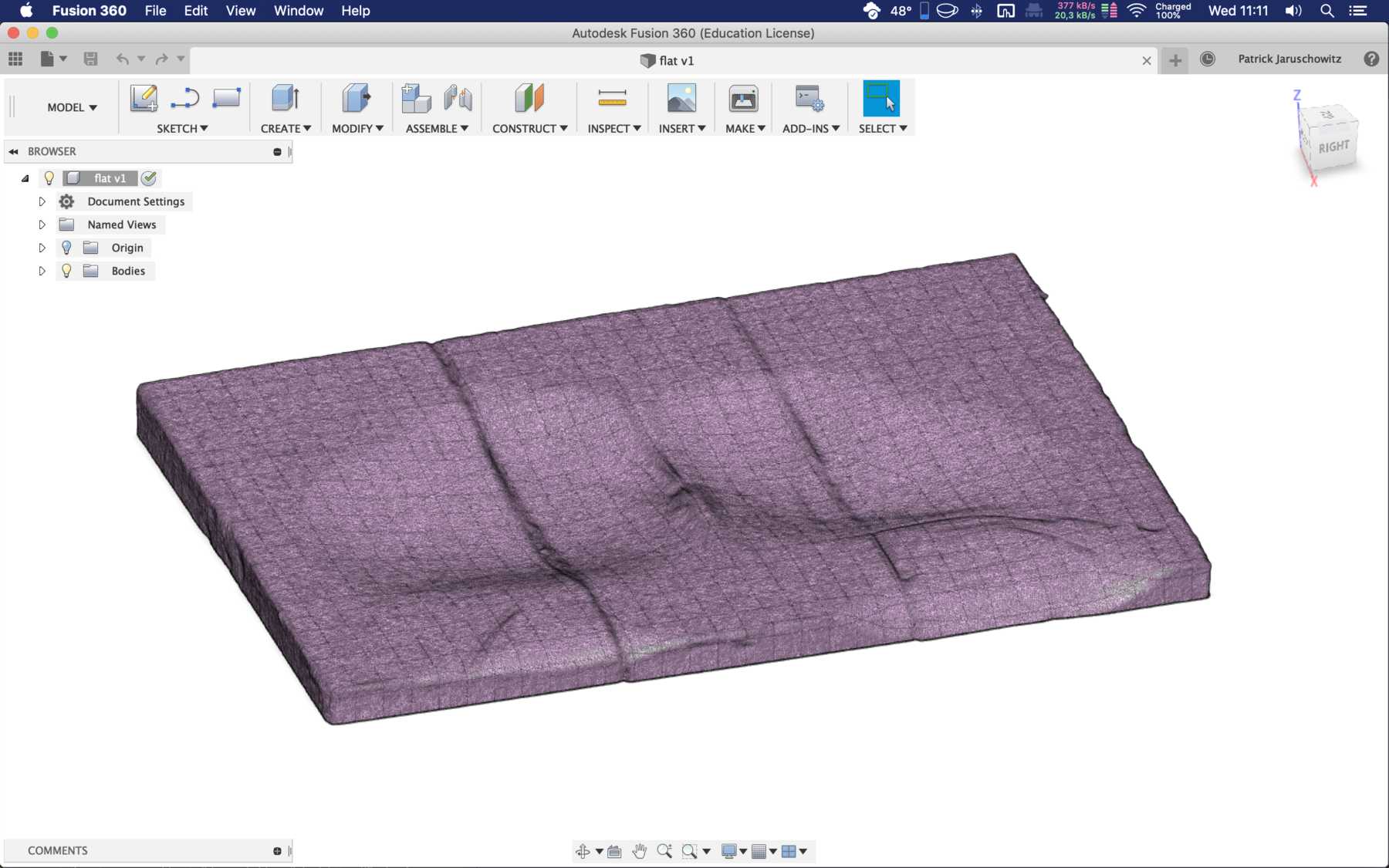
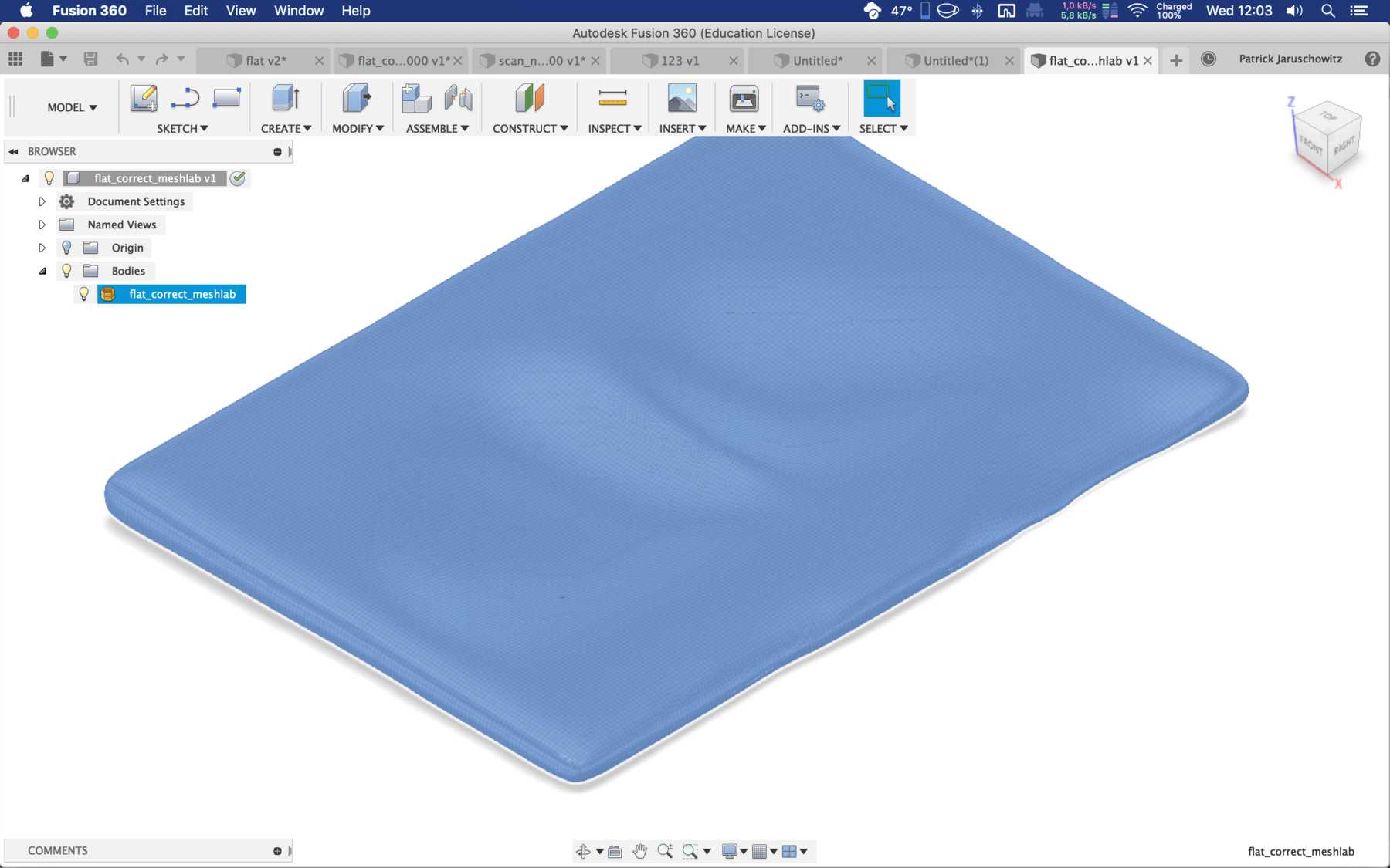
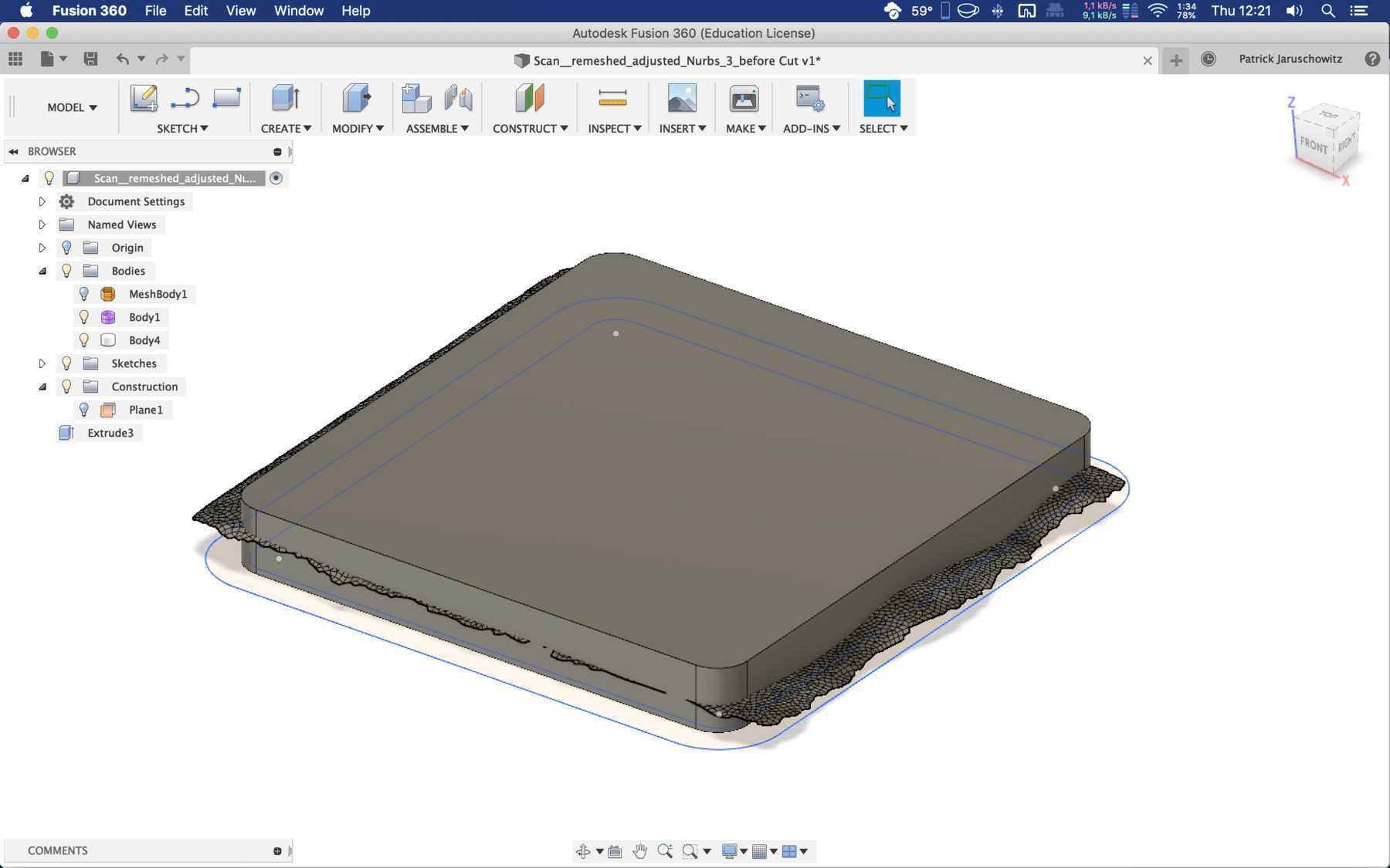
Import to Fusion 360:
- Convert to Brep
- Sketch shape of the seat on construction plane
- Sketch needs to be smaller than the surface
- Extrude enough over the surface
- Split body
- Tool != scanned surface
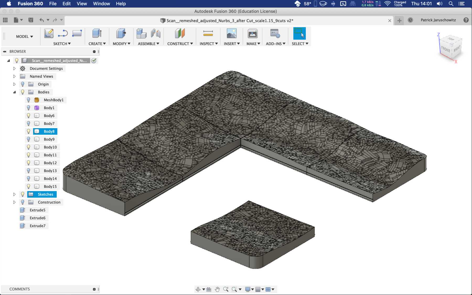
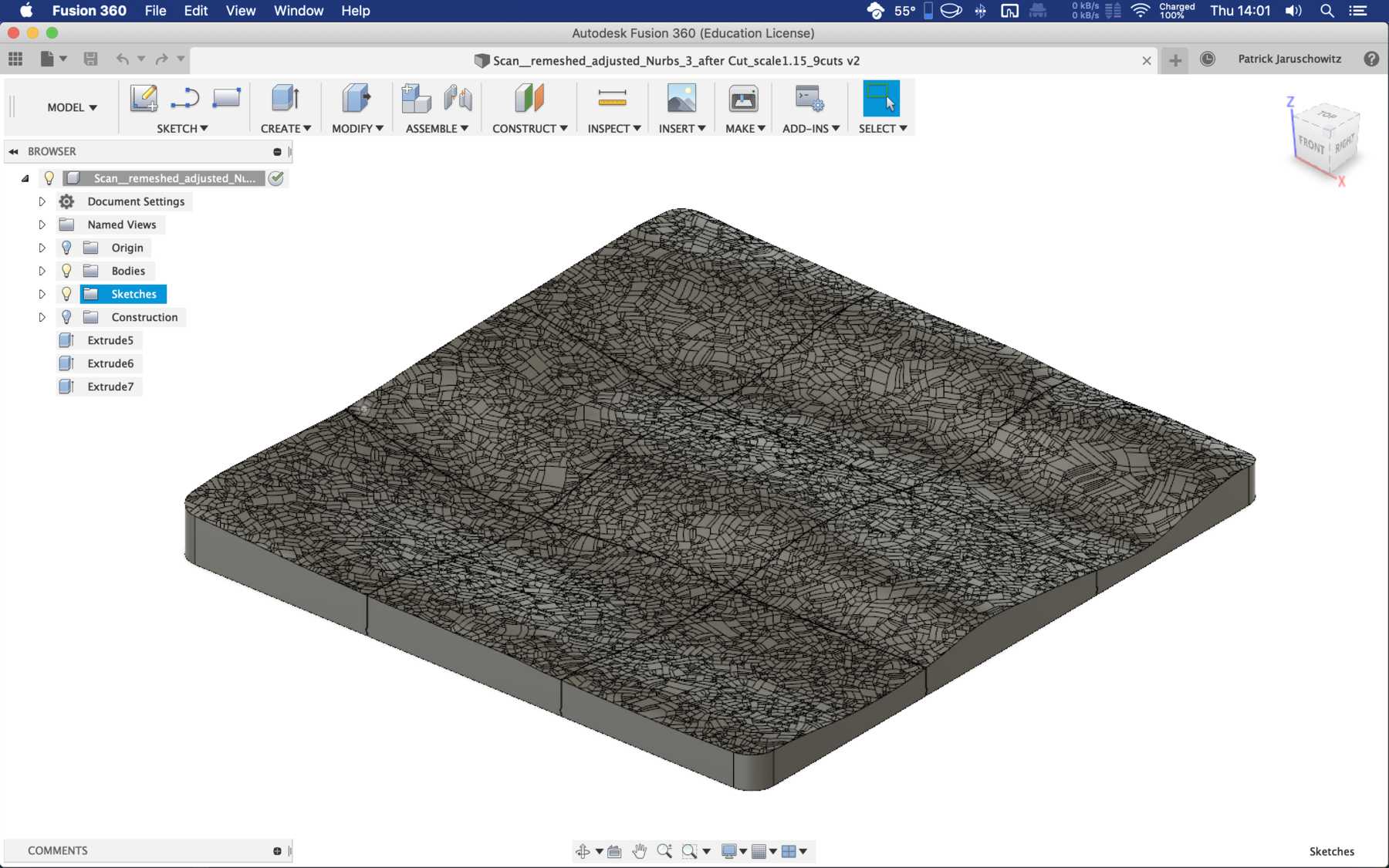
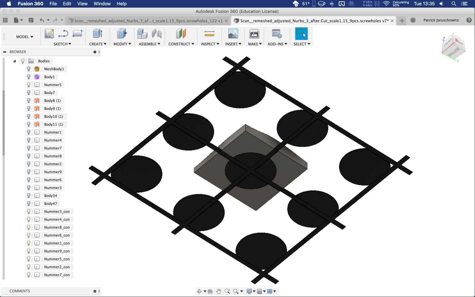
- Sketches & extrusions to cut into 9 pieces.
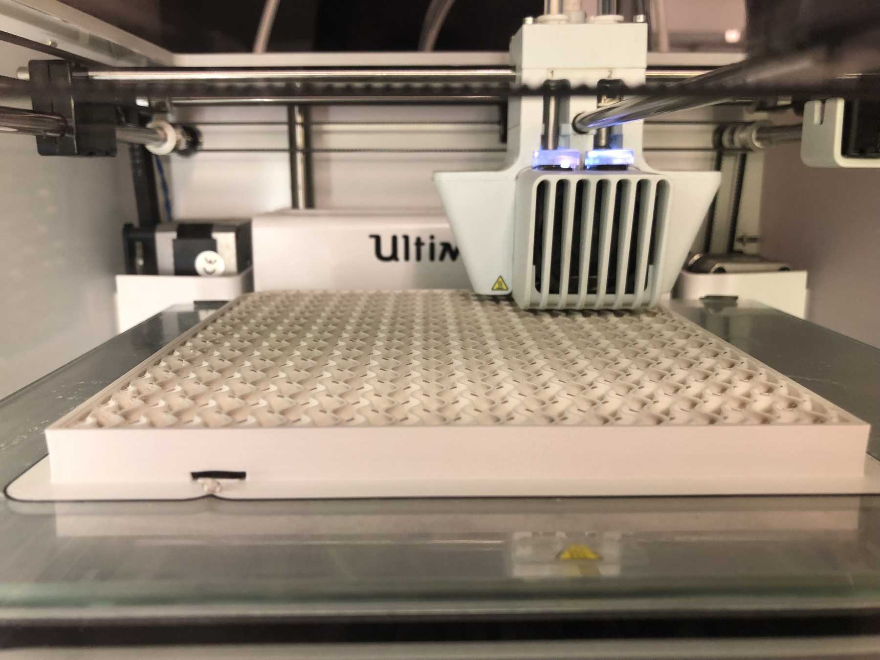
Then below was the ground layer made of conductive filament. I intentionally left it as large as possible so that you can leave enough variation in it later. The model was divided into 9 parts so that they can fit on the Ultiamker 3. The seat was also scaled approx. 5 % so that the foam mat would not lose its shape later on. According to this workflow, the model in Fusion 360 looked as follows:

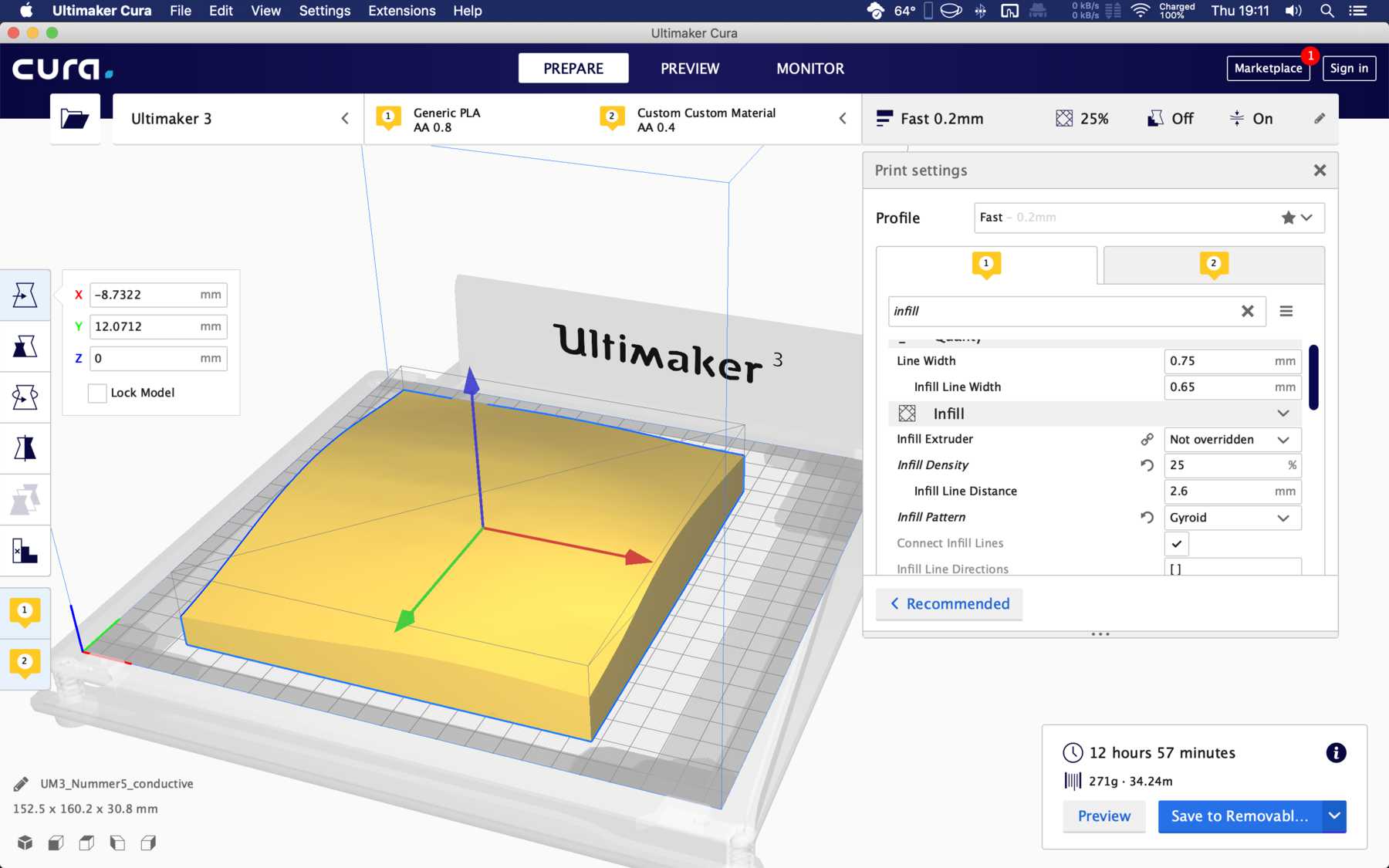
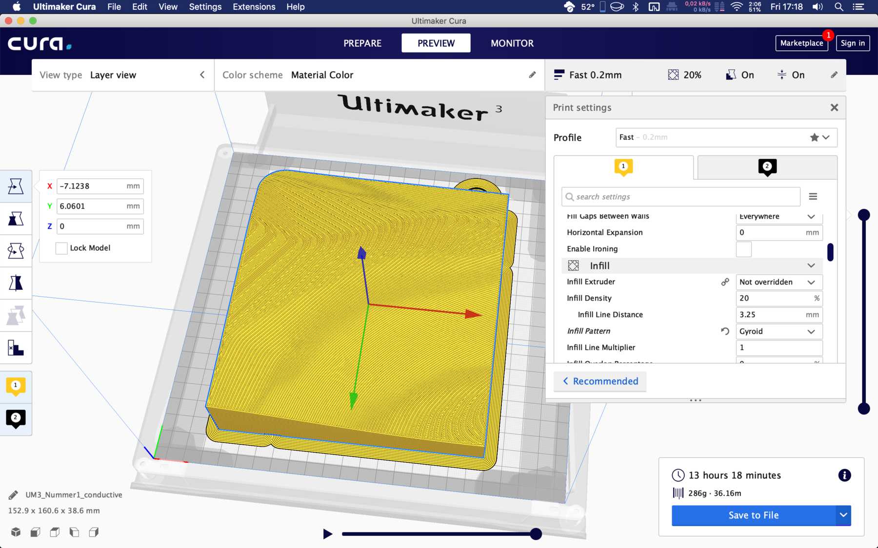
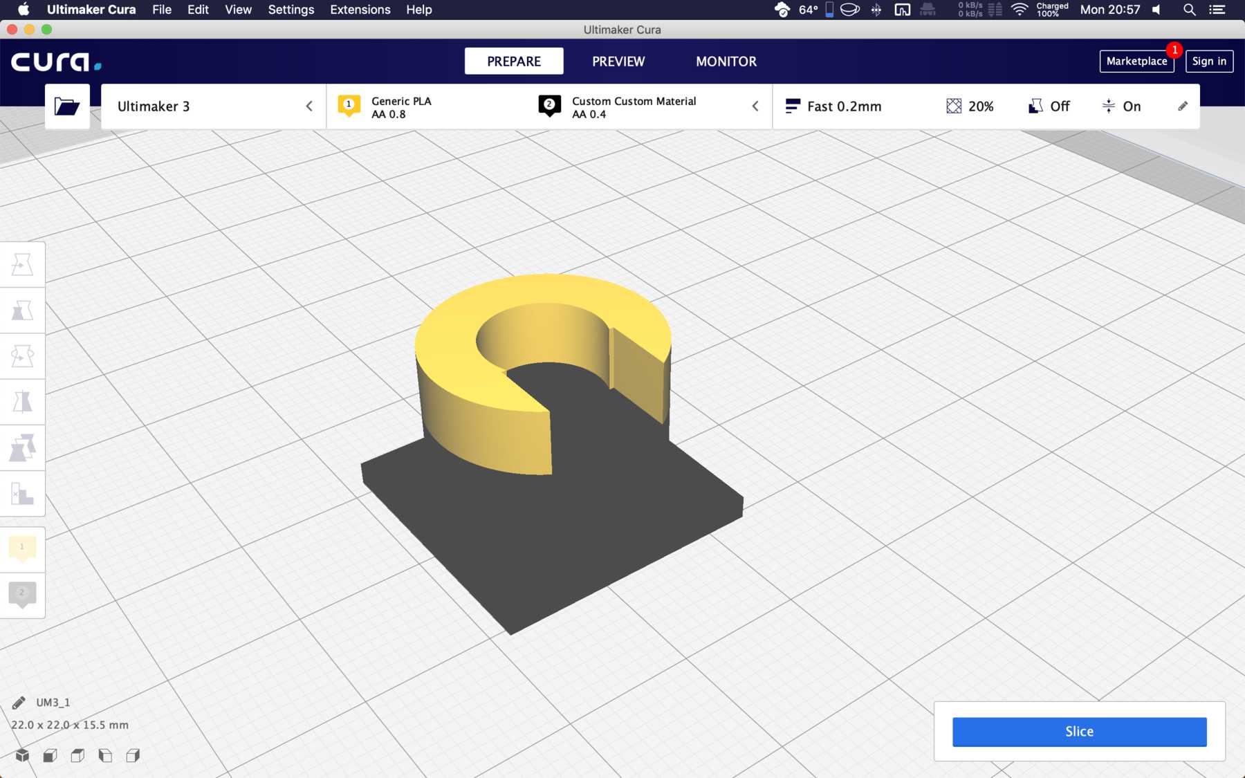
The print settings in Cura were as follows:
Material PLA
- Fast Print - 0,2mm layer height
- Printing temperature 205°C
- Support activated
- Support density 15 %
- Brim activated
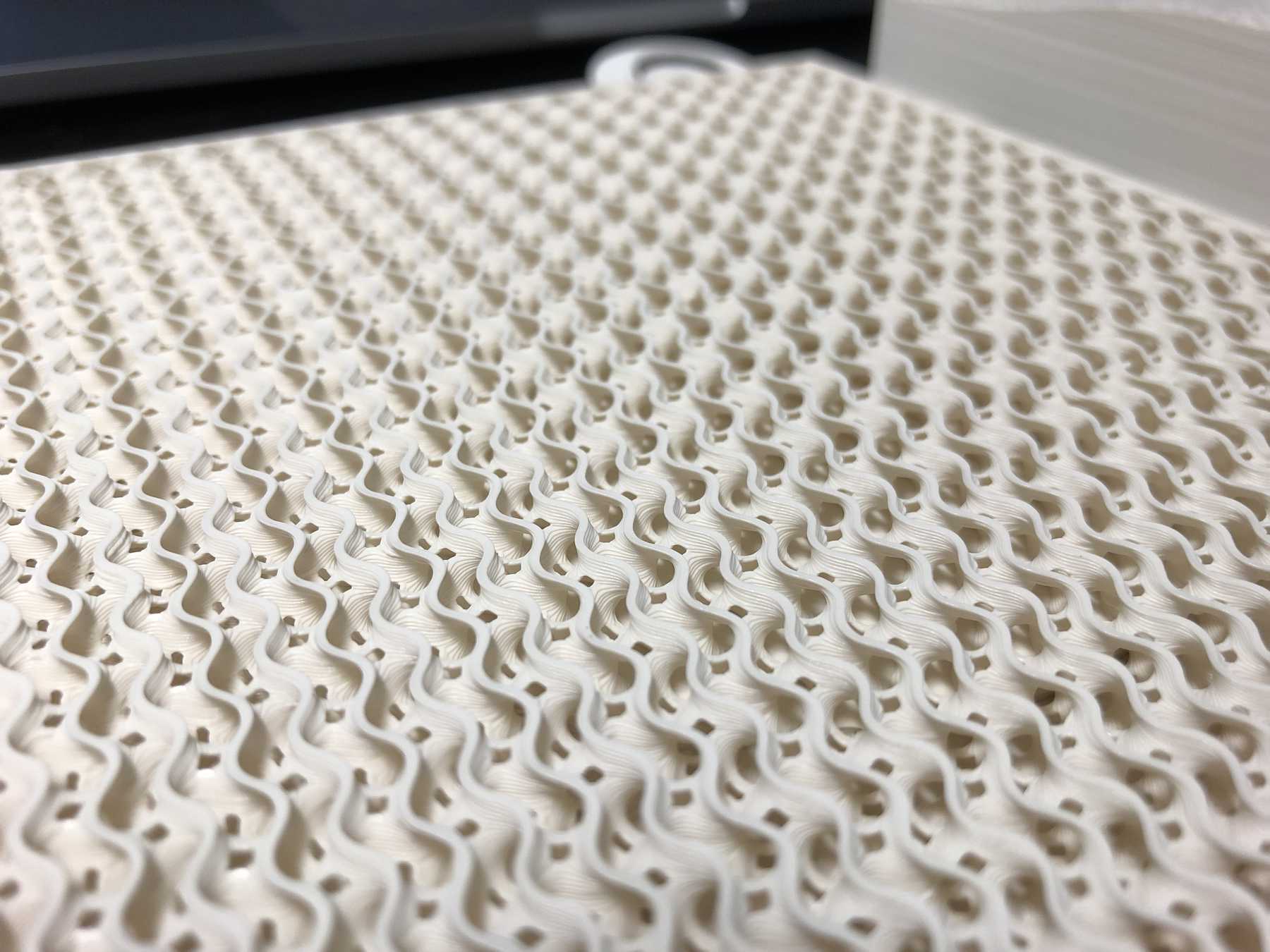
- Infill: 15%
- Infill pattern: Gyroid
Material conductive
- Printing temperature Conductive 215°C
- Fast Print - 0,2mm layer height
- Brim activated
- Infill: 100%
Printing temperature PLA: 205°C Printing temperature Conductive PLA: 215°C
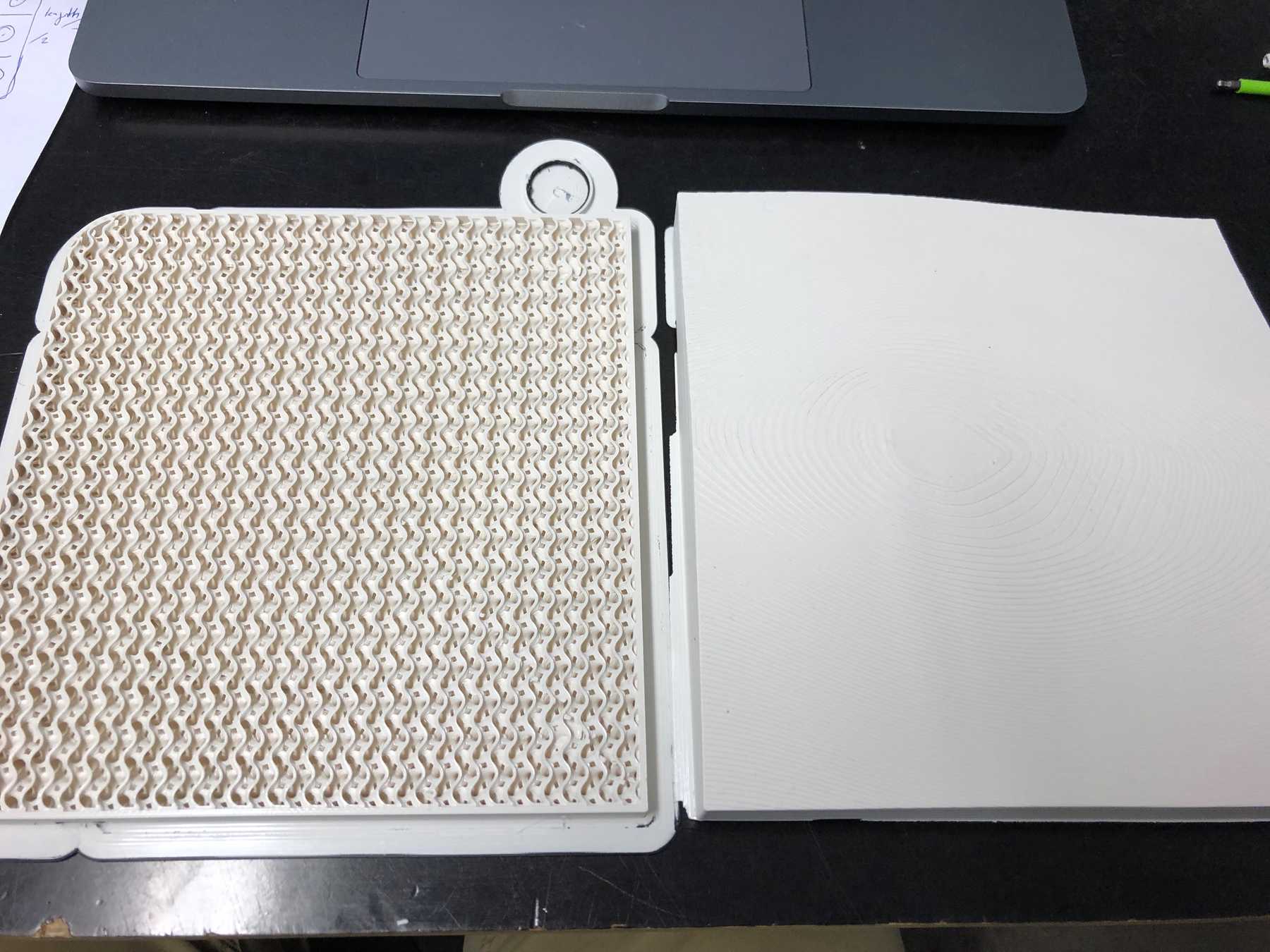
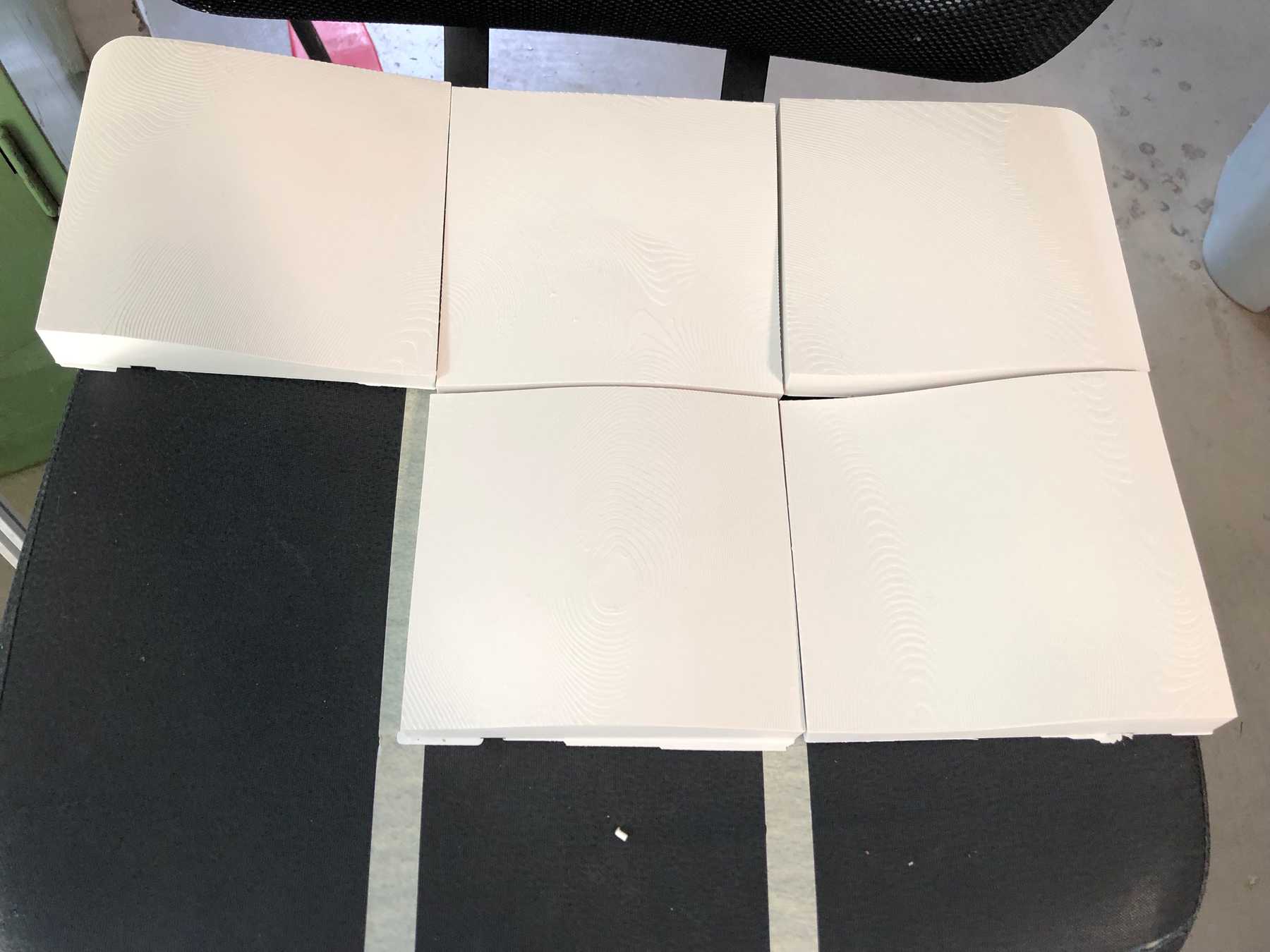
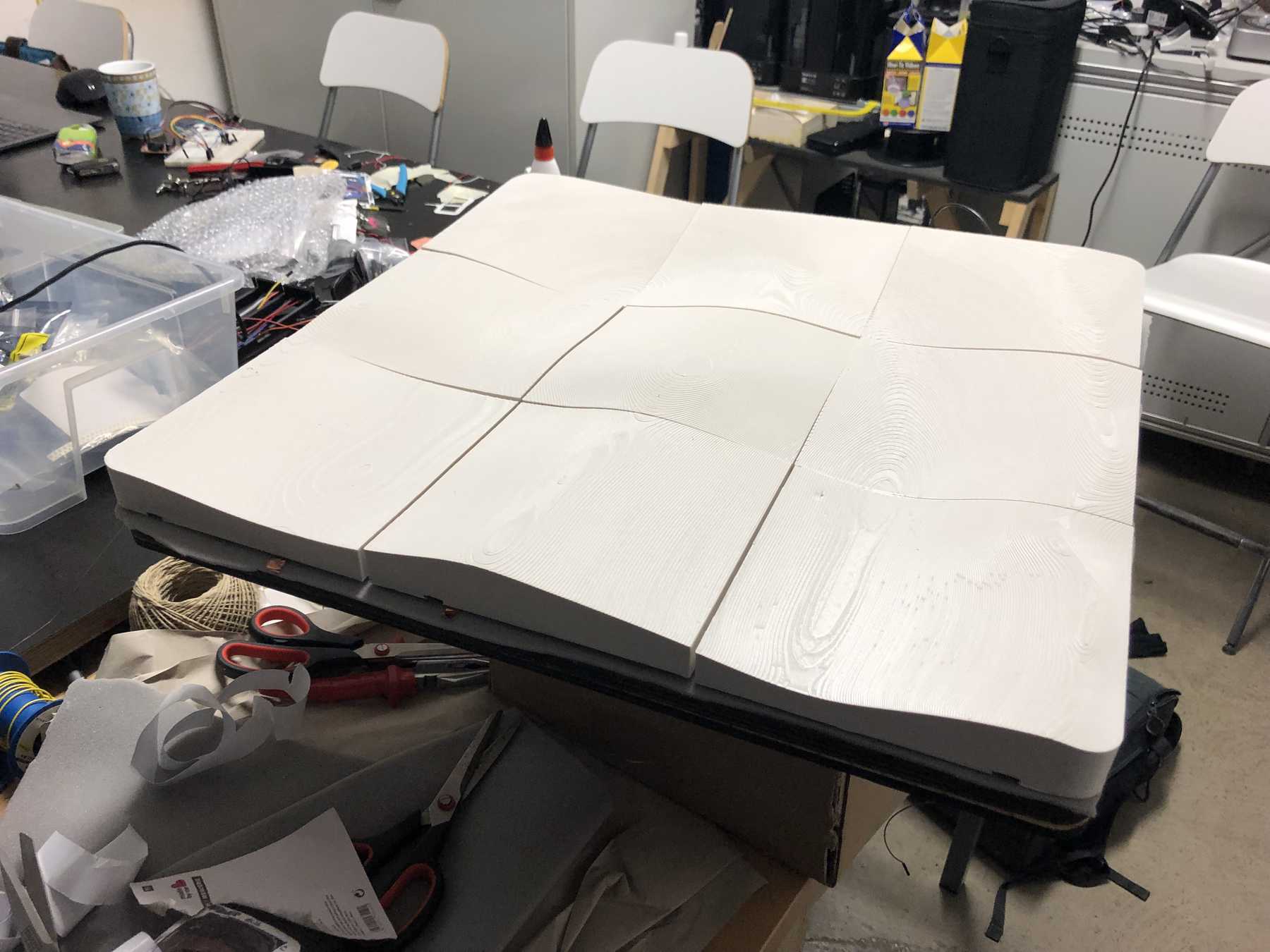
First I printed it out in small and checked if everything would fit.
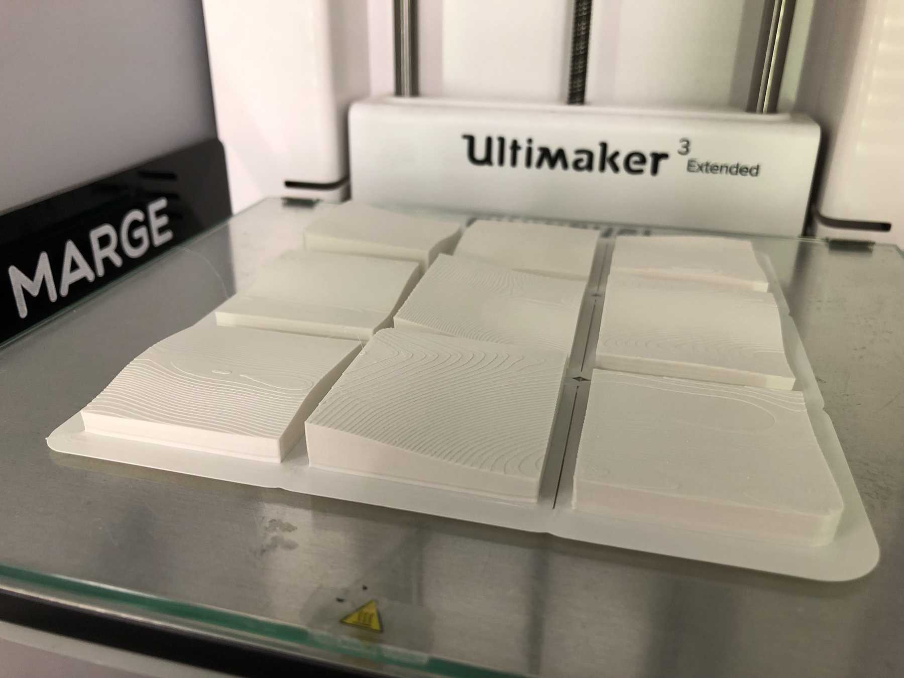
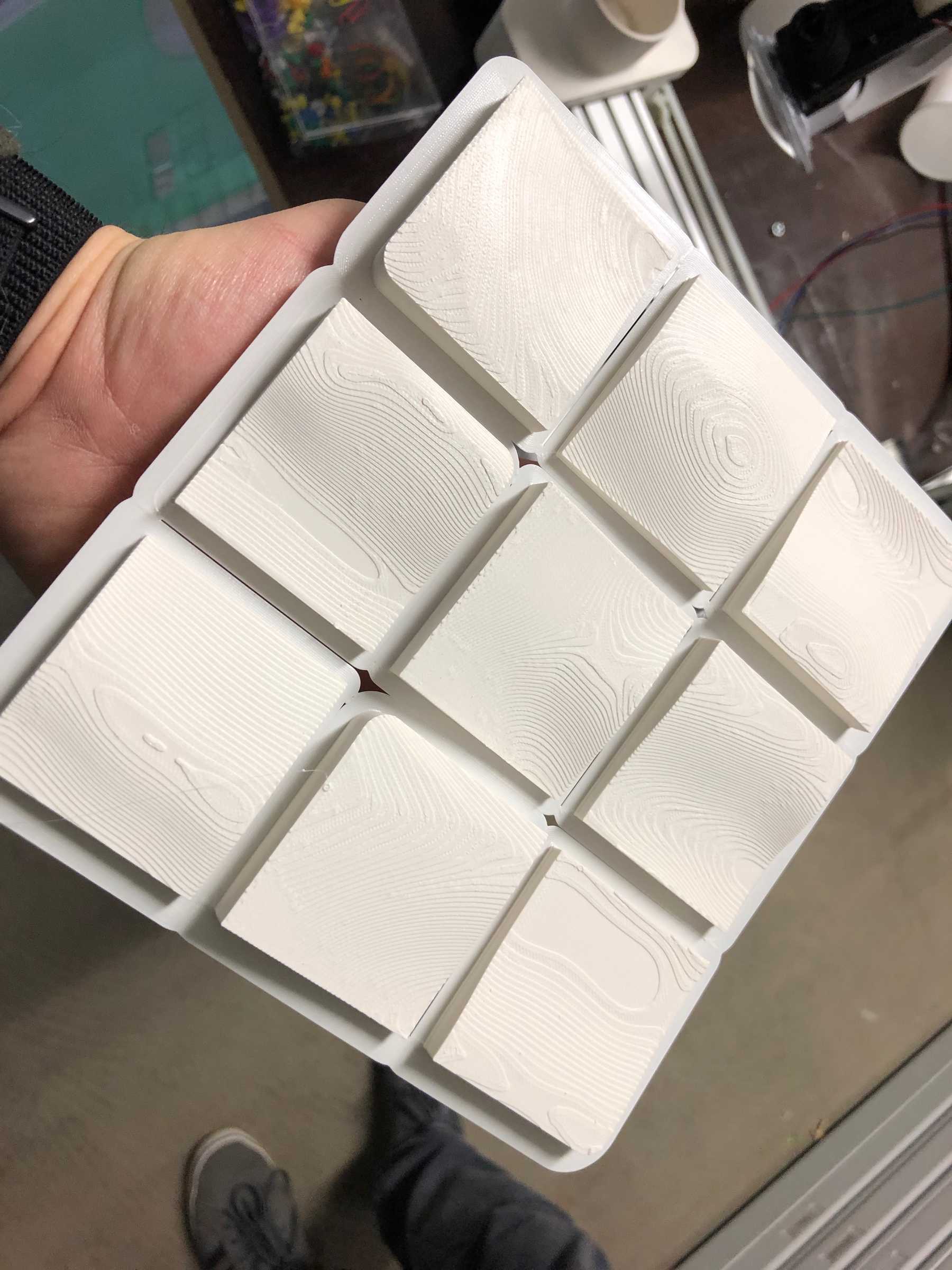
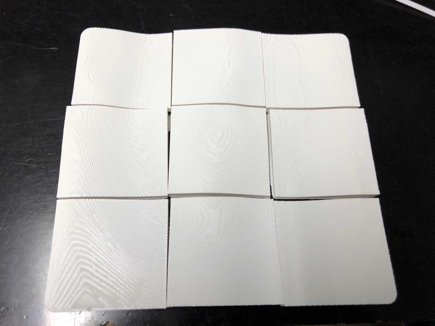
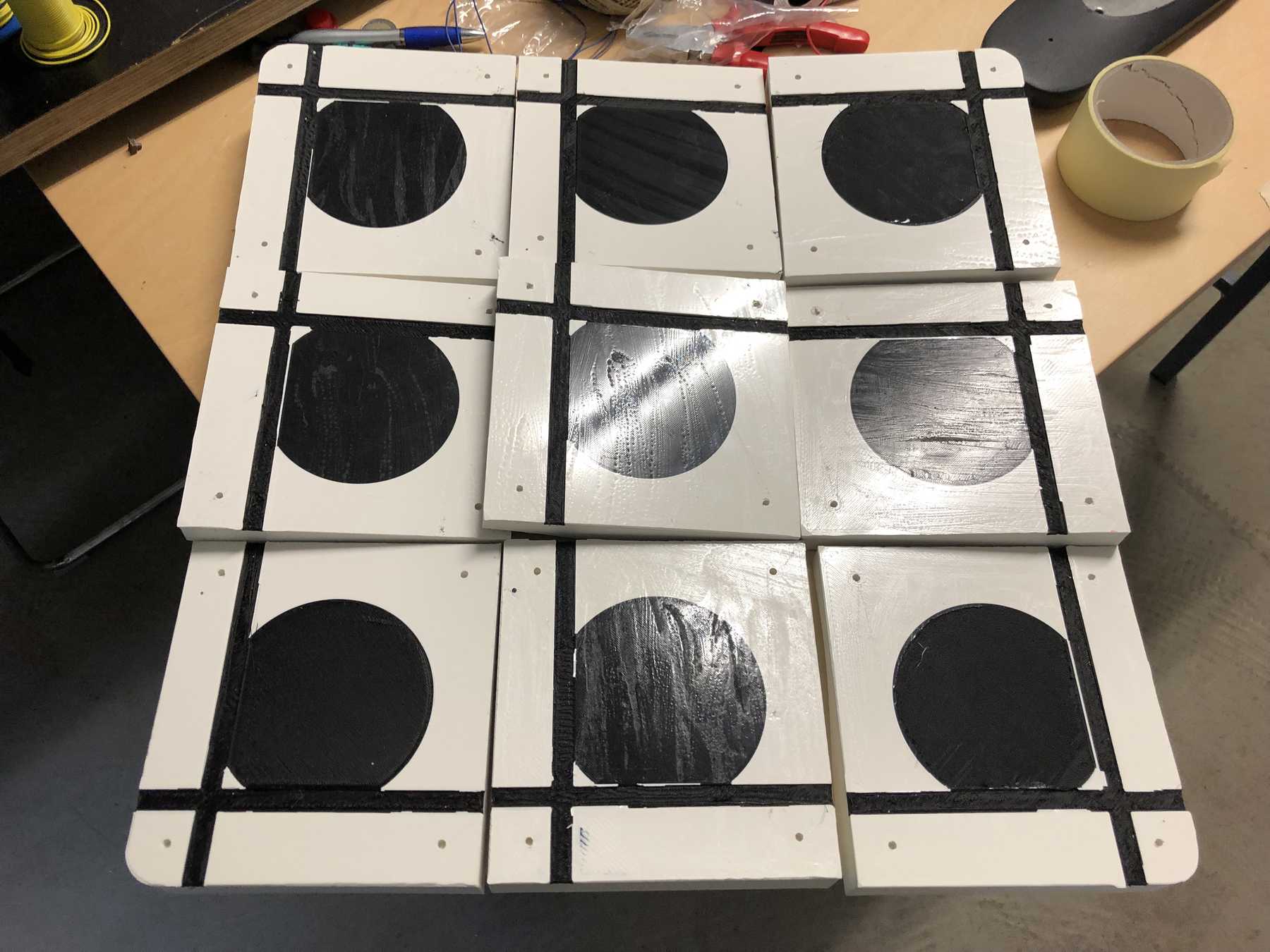
The whole thing was then put together, so a puzzle of my butt. How exciting.
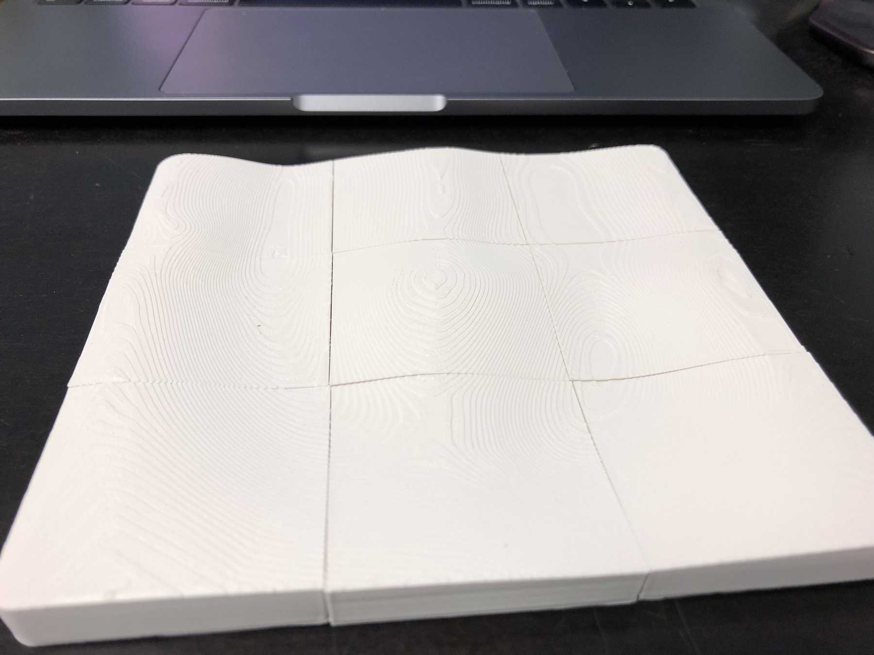
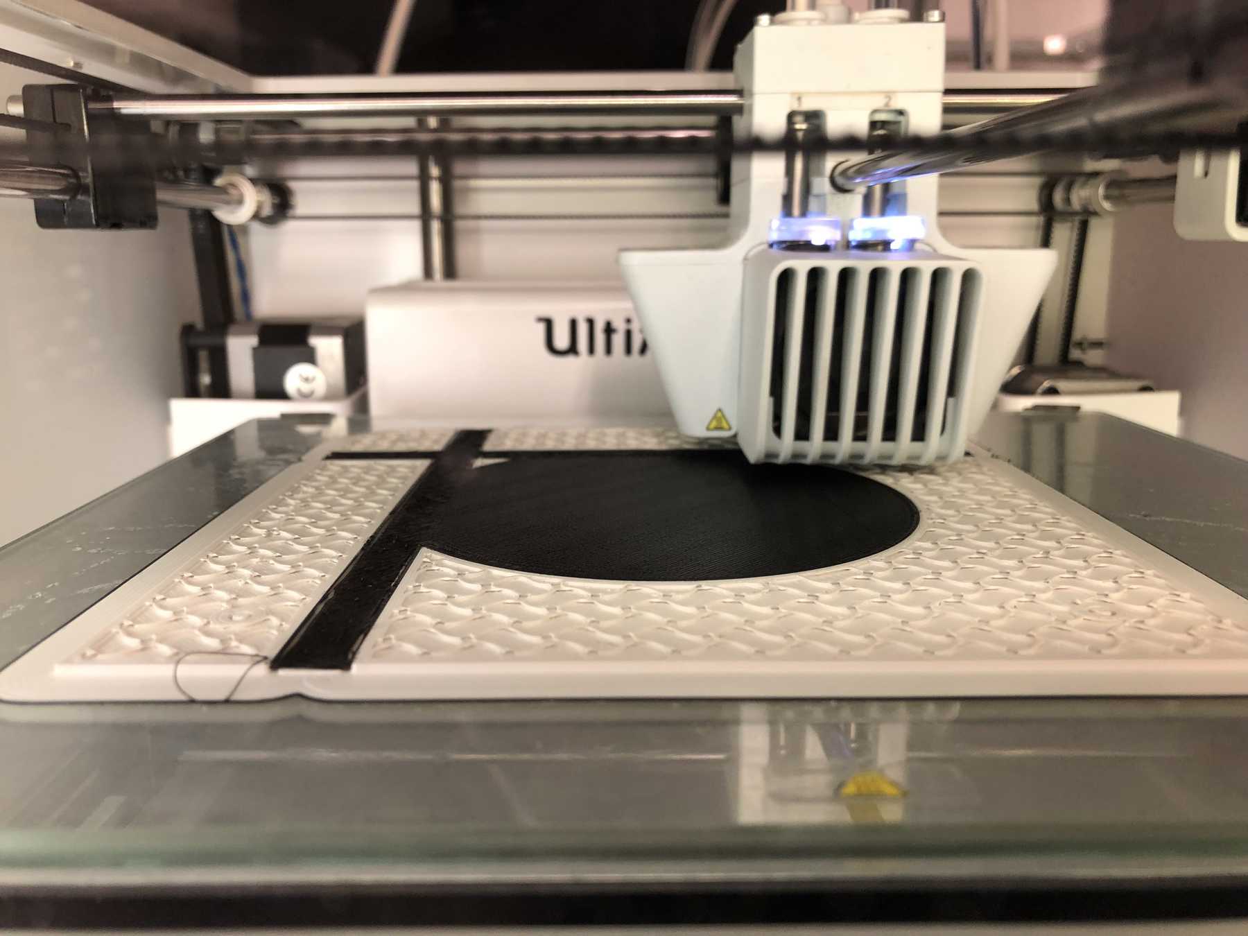
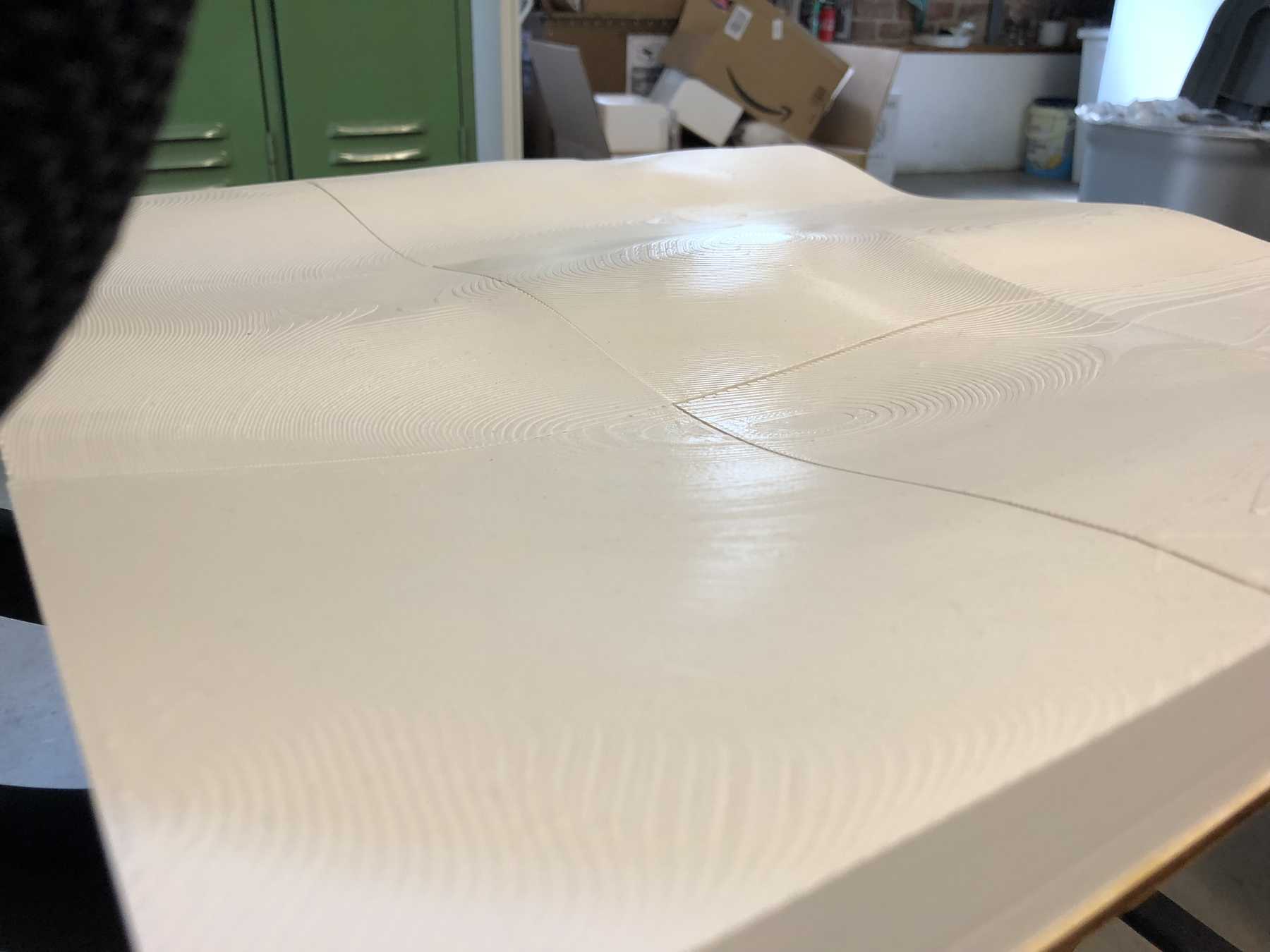
The first result looked good. The conductive filament as a ground layer was to be joined later by a copper foil. Now it was time for big printing. 9 parts - Four printers - Two days. That was the calculation. All parts should be printed by Saturday. The first print still worked and looked good:
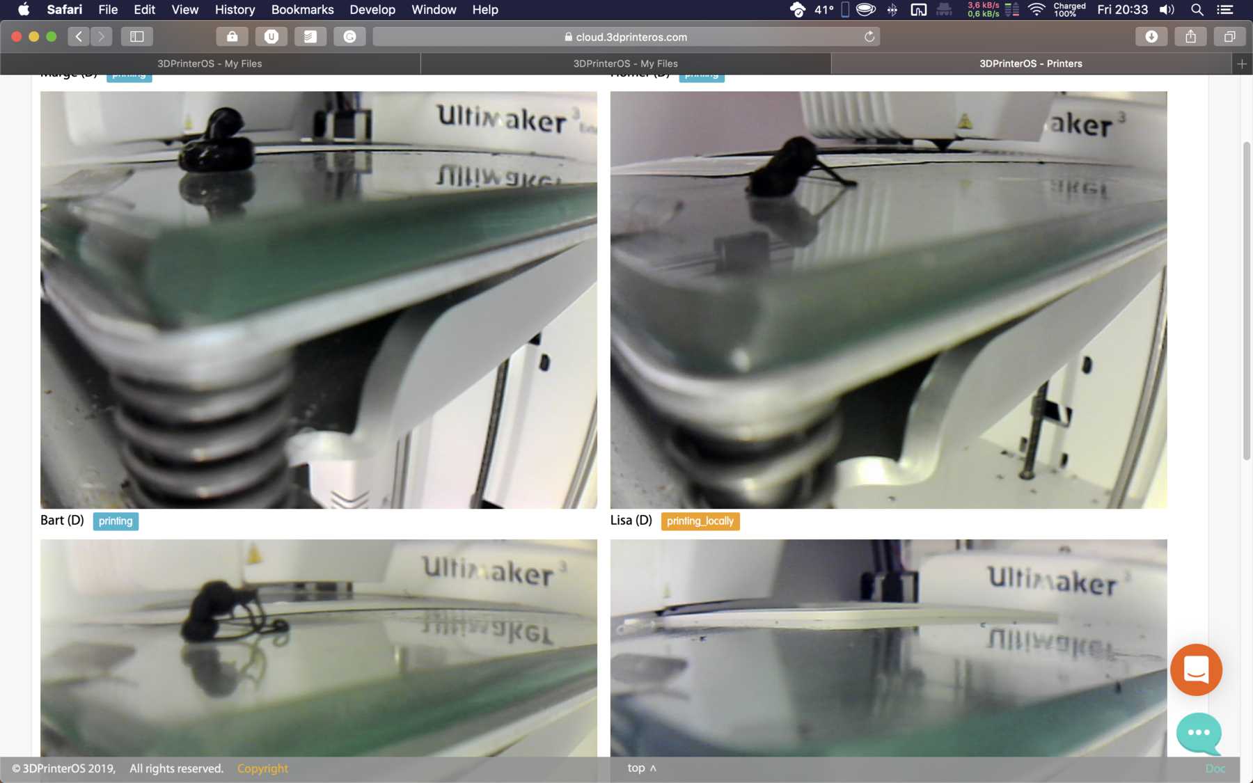
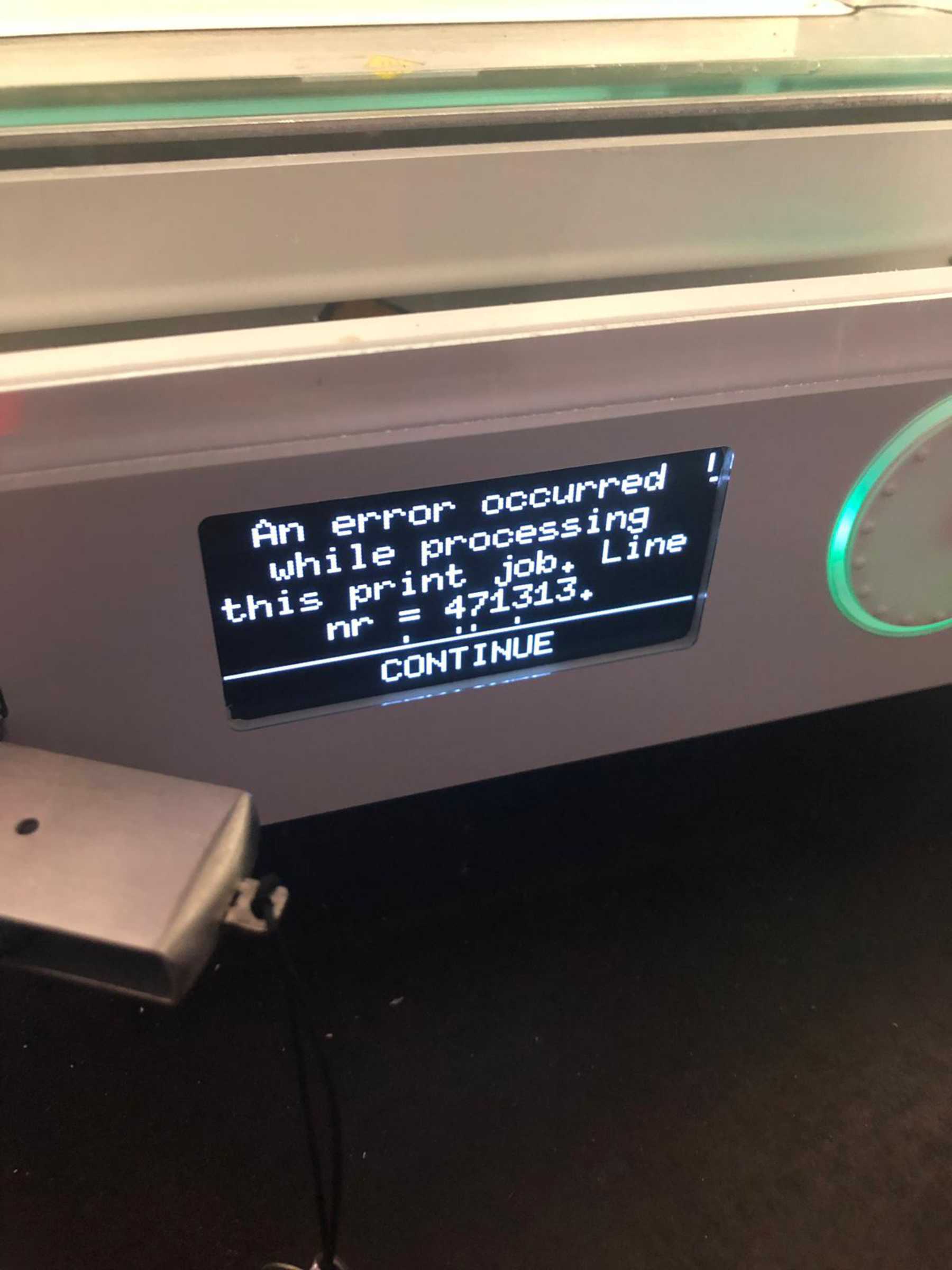
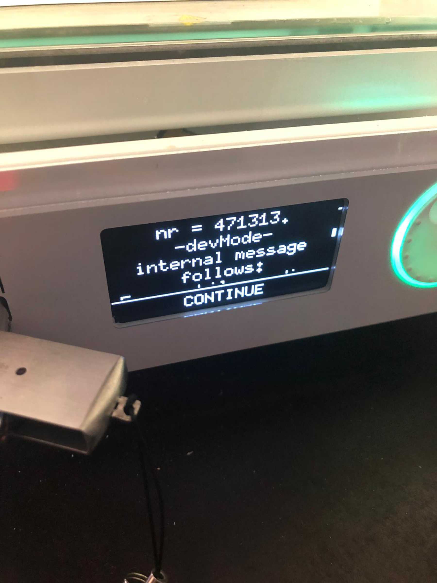
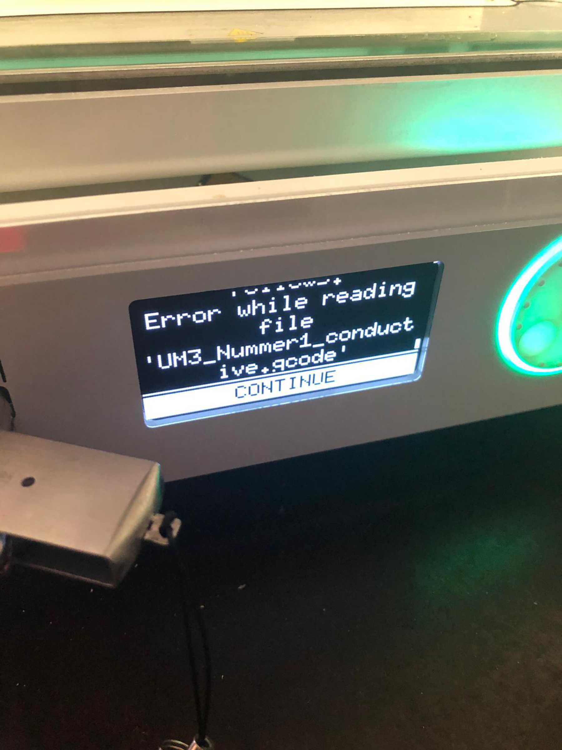
The second print, on the other hand, crashed. One of the first prints in a long time over a USB stick. So no, thanks. Back to the cloud solution and the prints are on.
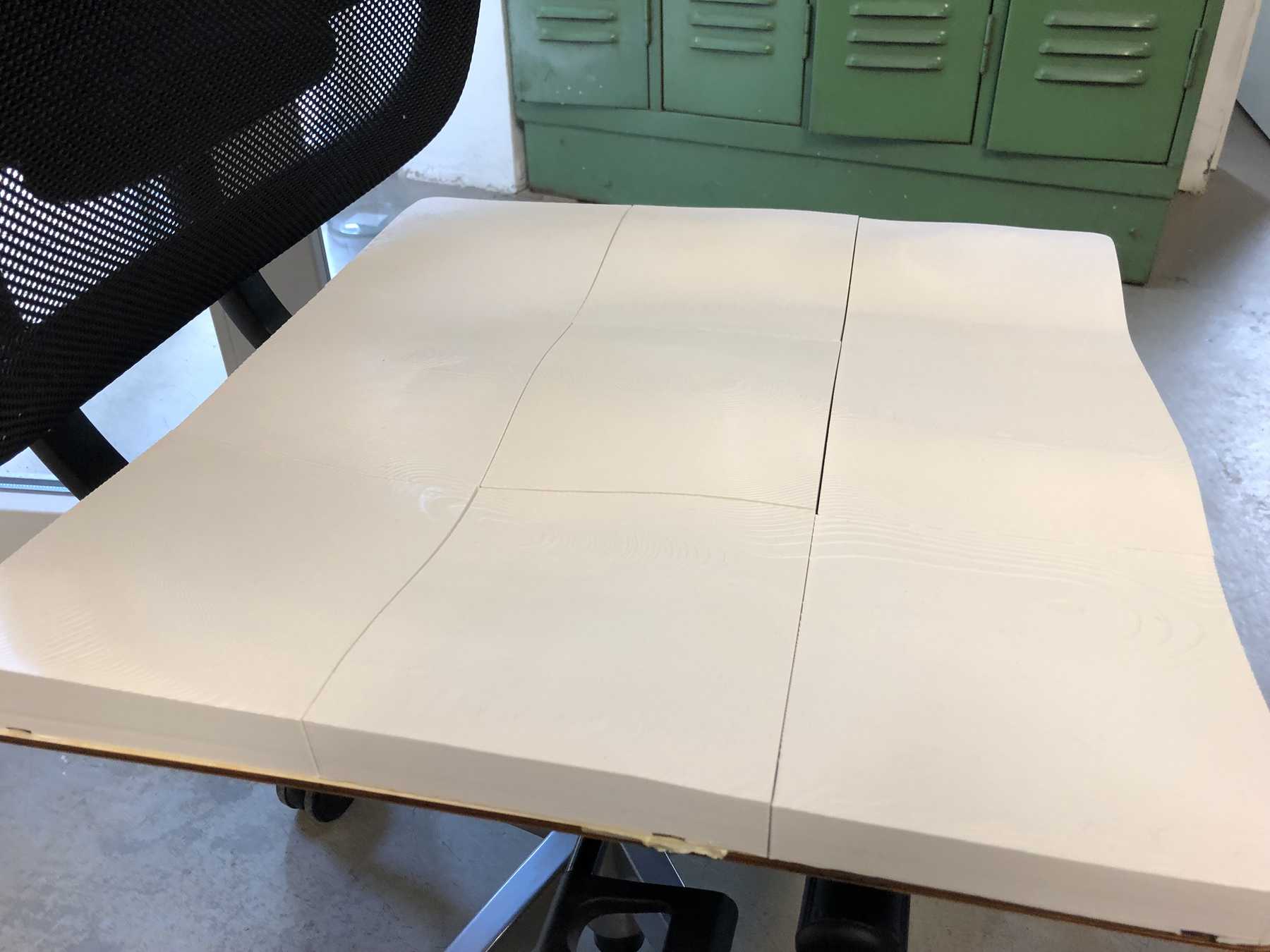
The results were acceptable. One after the other the seat became bigger and bigger. Later, the four holes were to be positioned and fastened using screw heads with the seat plate.
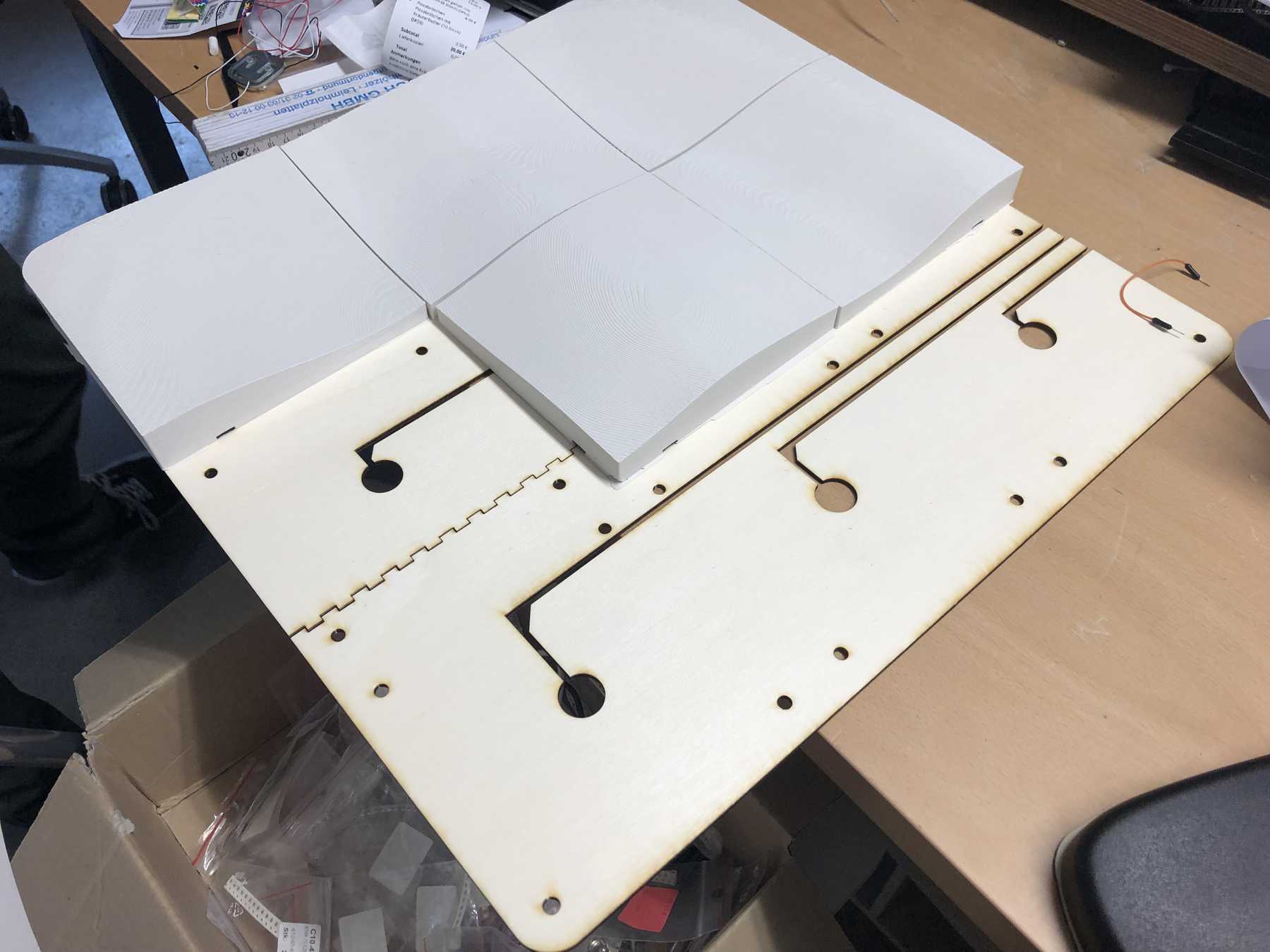
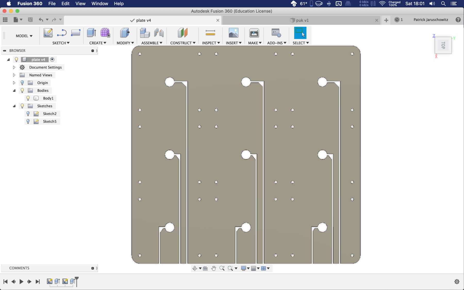
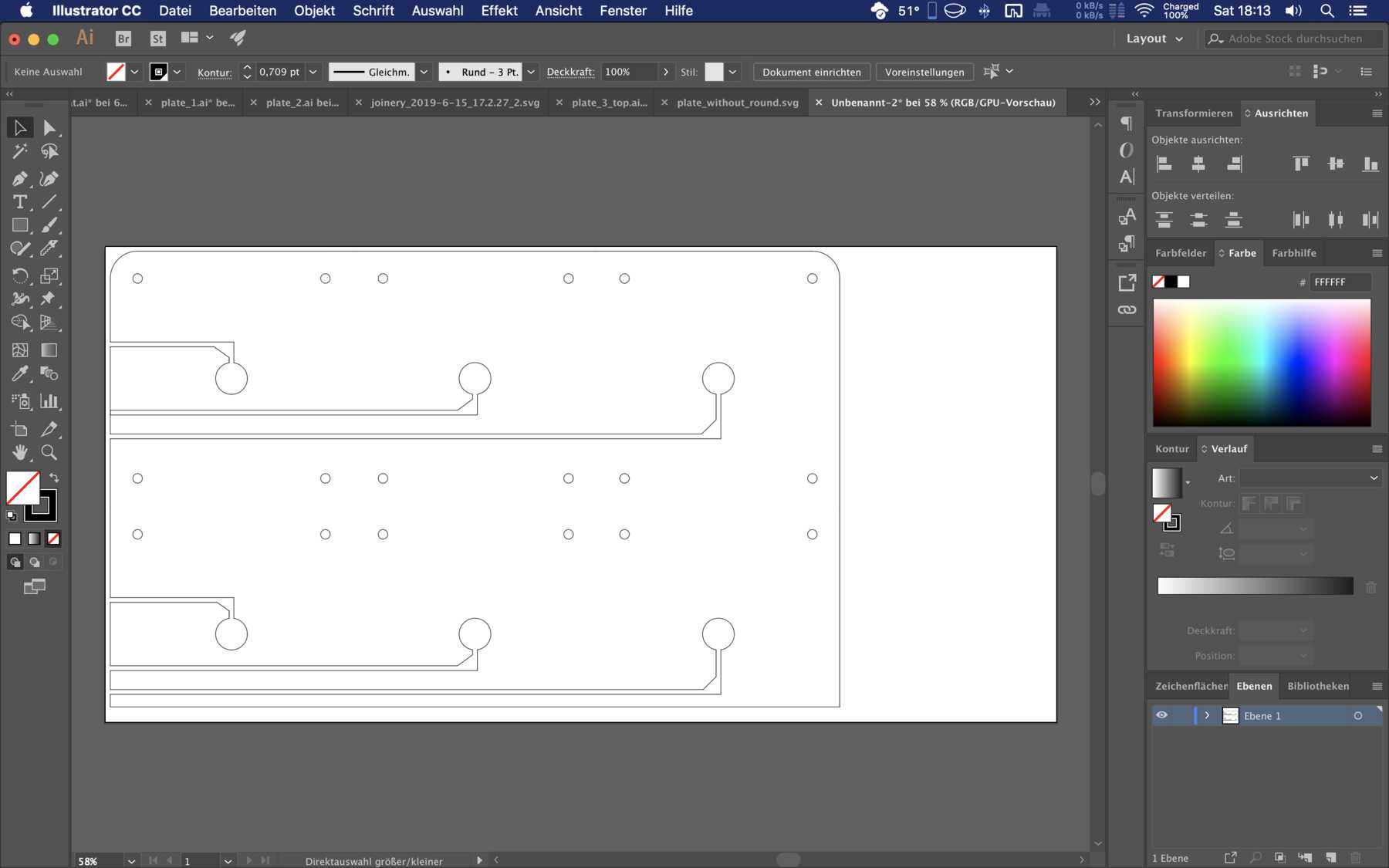
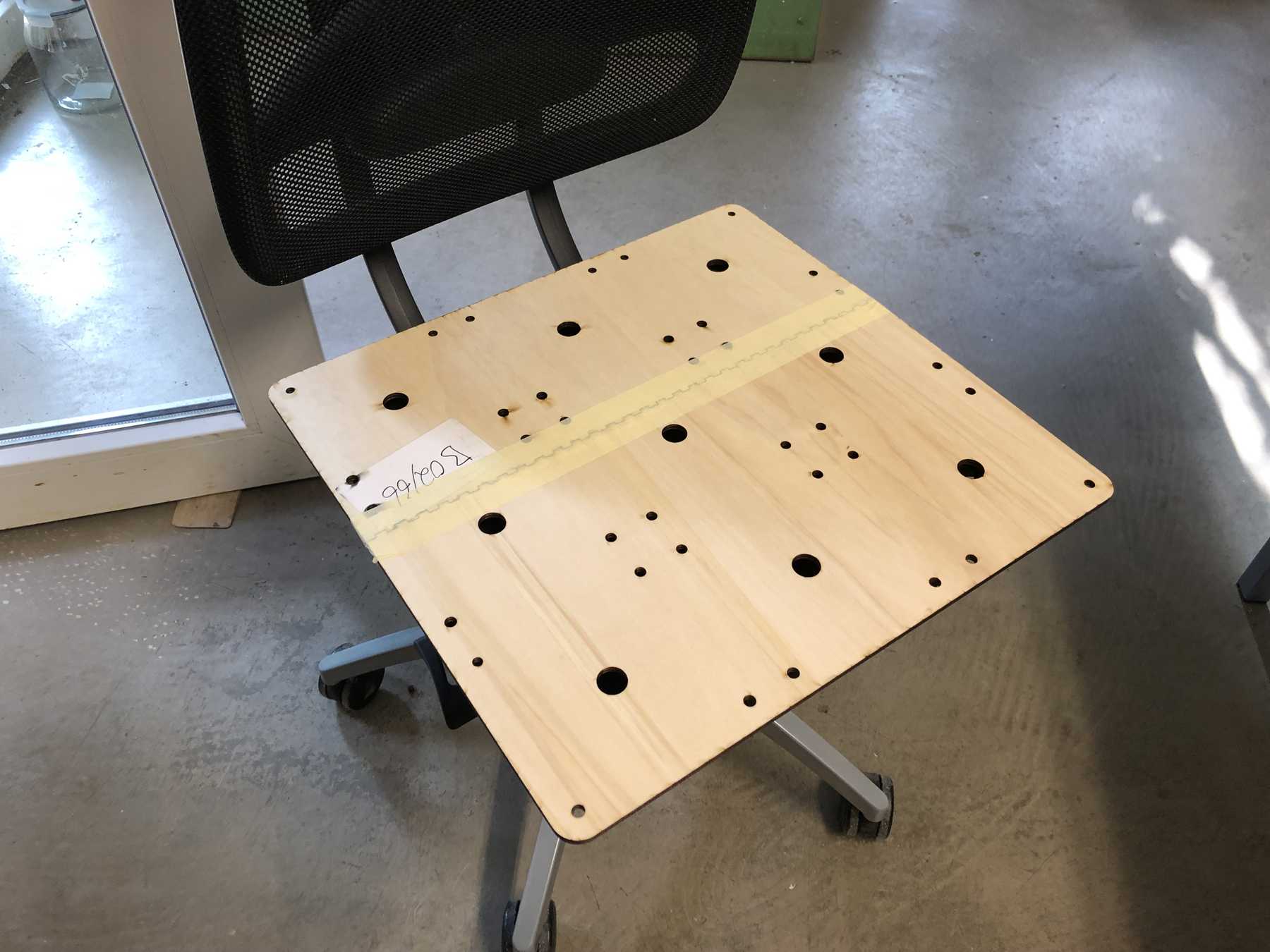
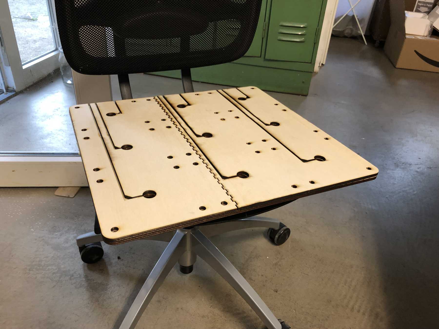
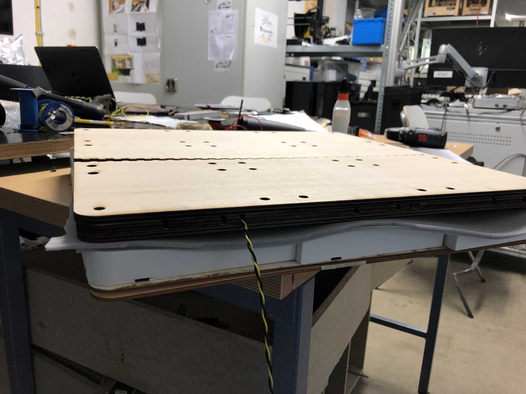
Designing the base plate
- In Autodesk Fusion transfer the shape and then edit it so that all the holes fit. Export as *.DXF file.
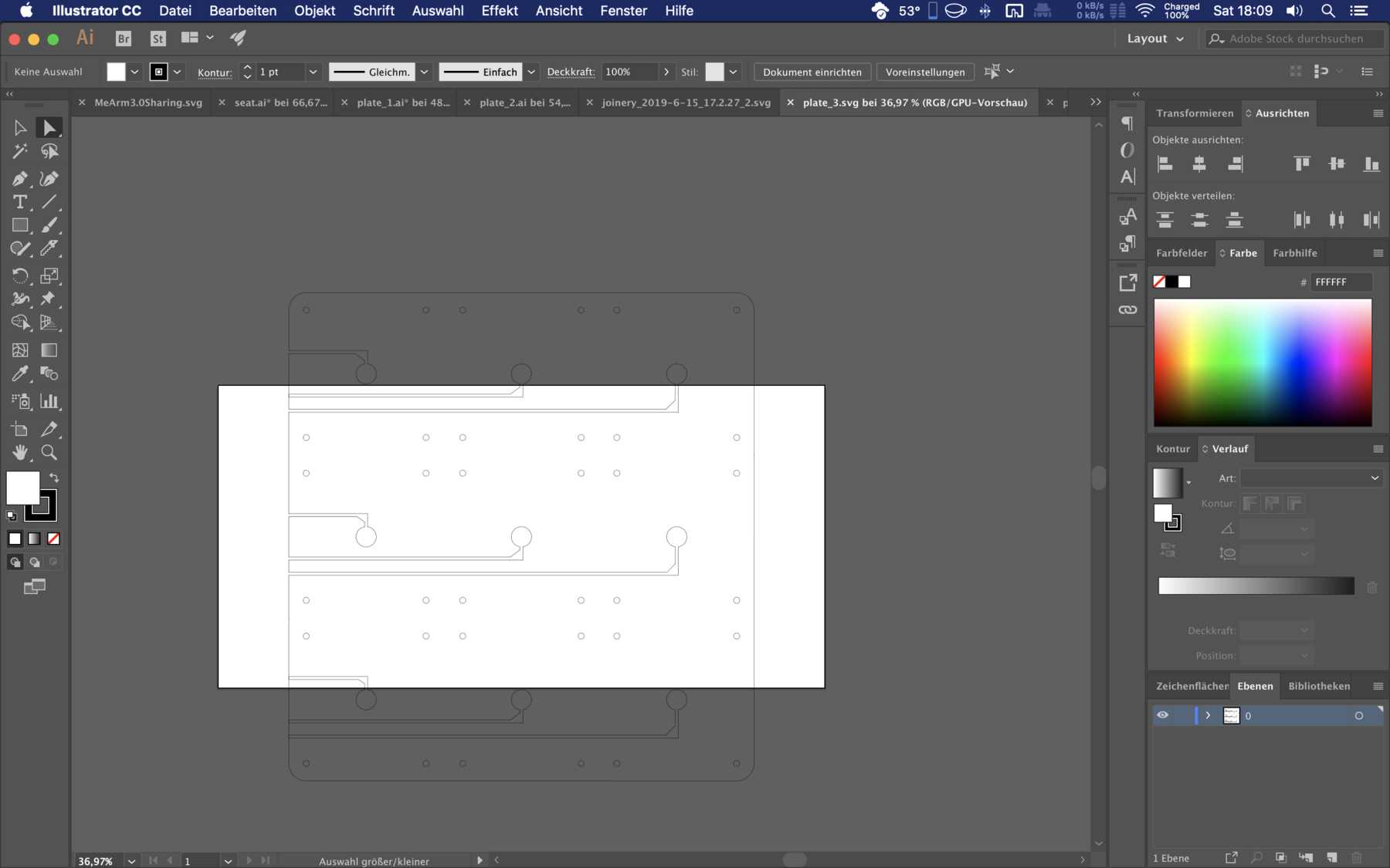
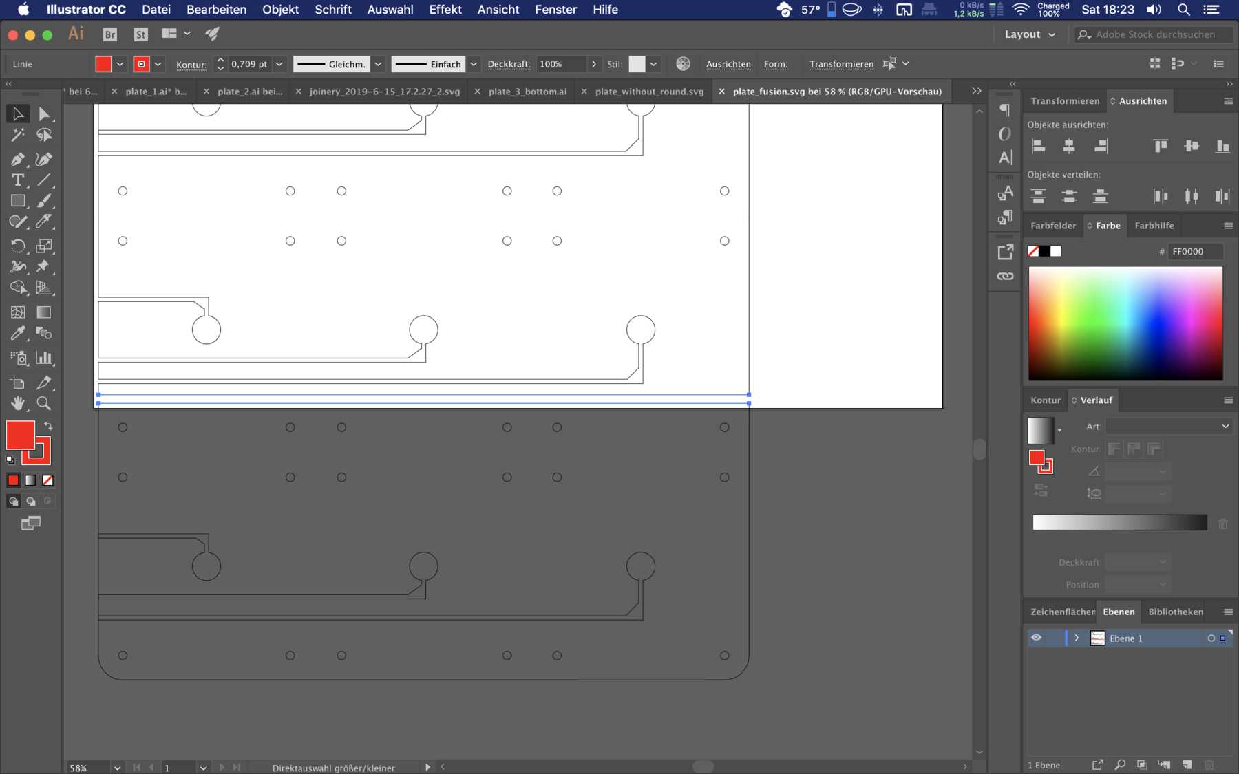
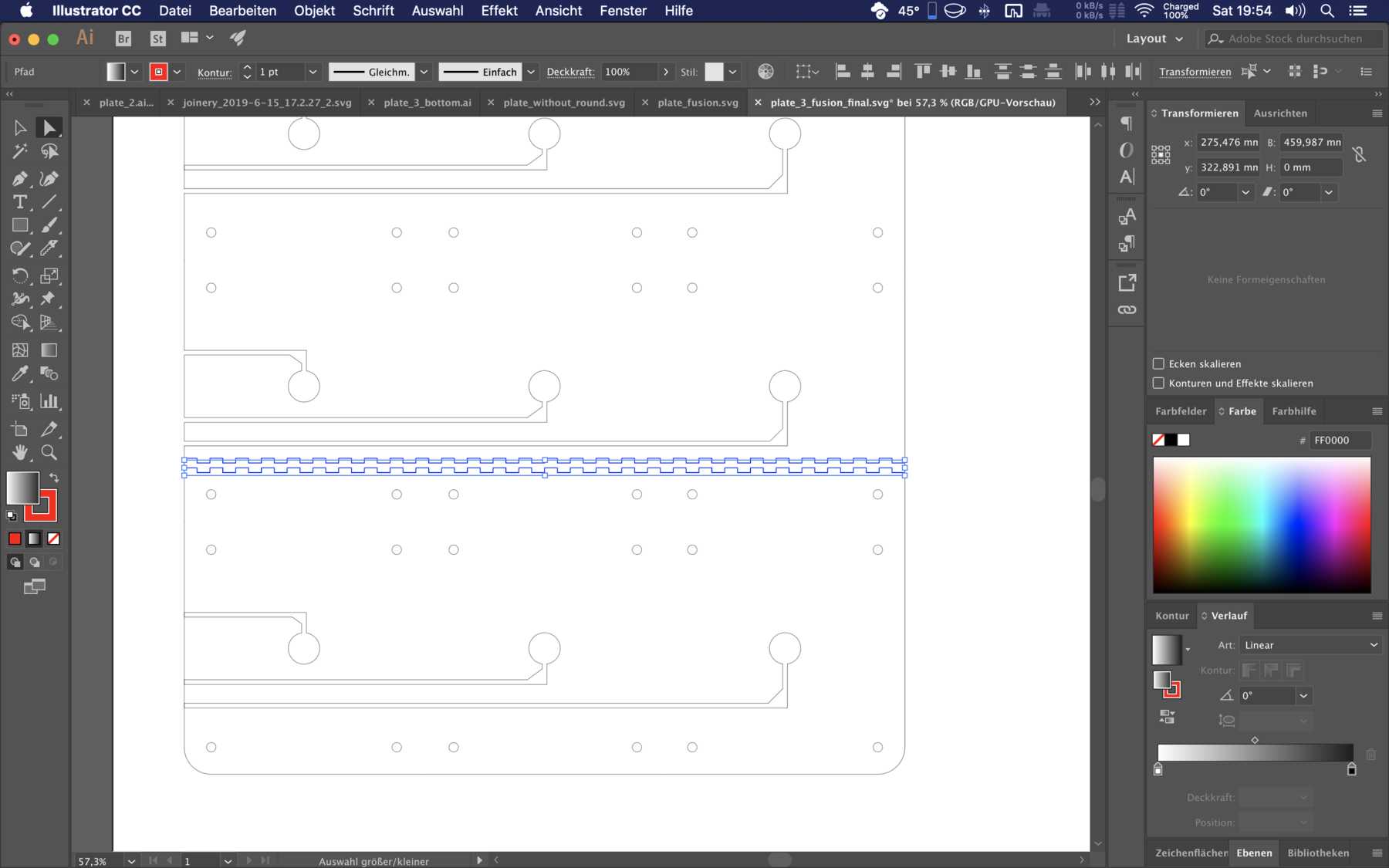
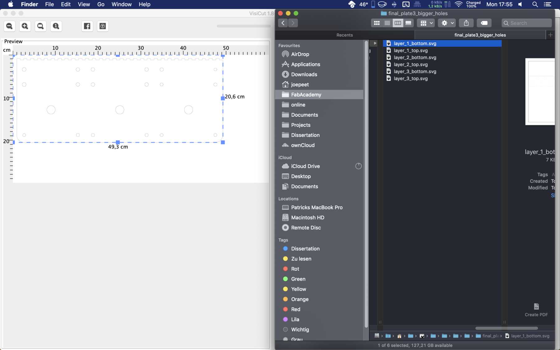
- Edit in Illustrator so that the object is edited in two parts for the area 600 x 300mm. This is the area that the laser cutter can process. Export as *.SVG file.
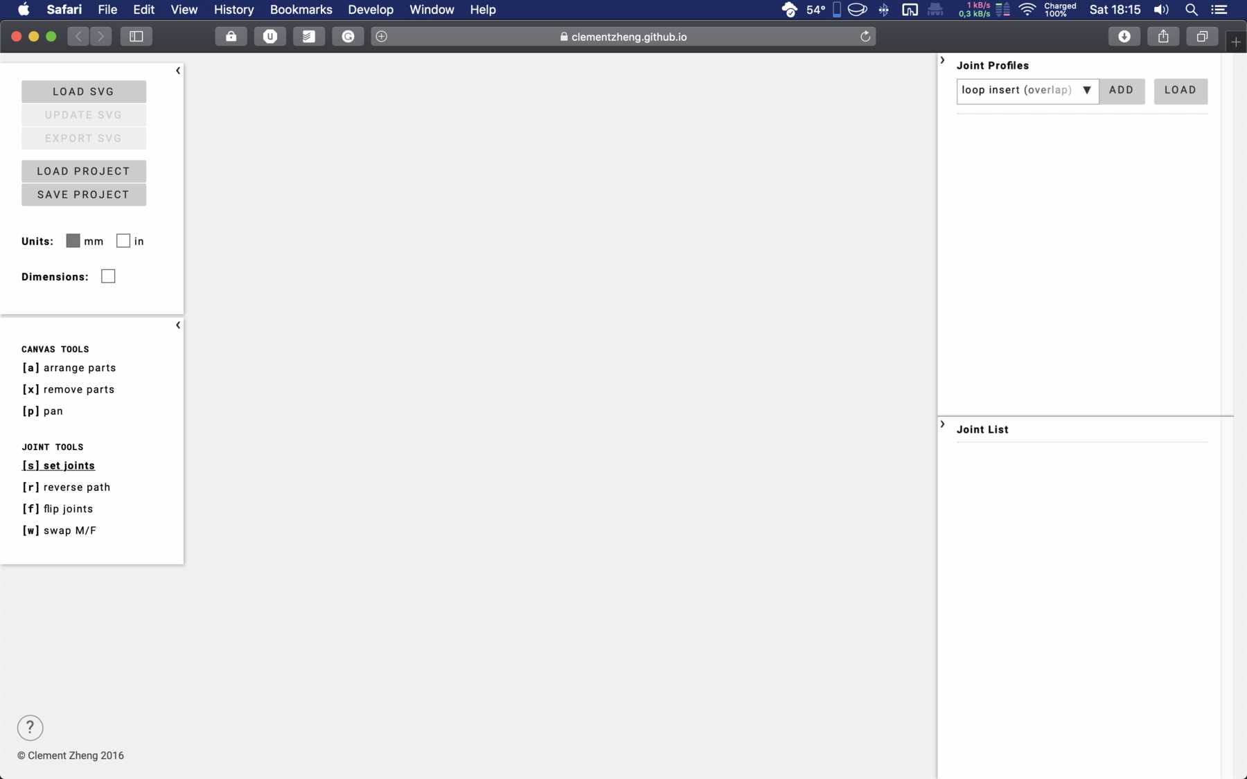
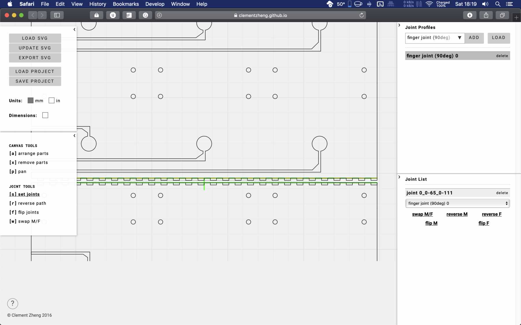
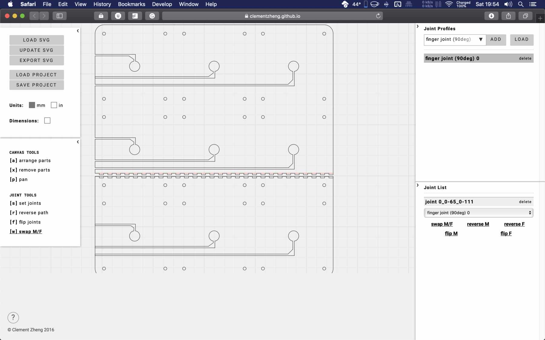
- For the connection options I used the online tool Joinery. Here you can create very helpful Joints for the respective edges. It is important to mark the edges you want to join. One option is to use colors, which I did. Export as *.SVG file for Visicut, so the laser can work with it. The whole thing looked like this:
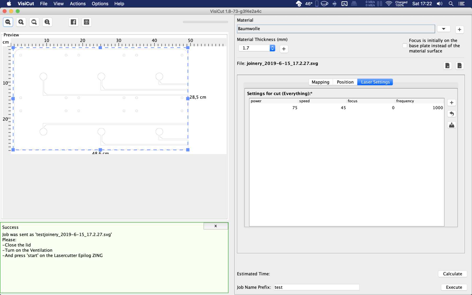
Sometimes he didn’t want to laser through the 6mm thick poplar wood plate. In these cases I did the procedure twice. The results were as follows:
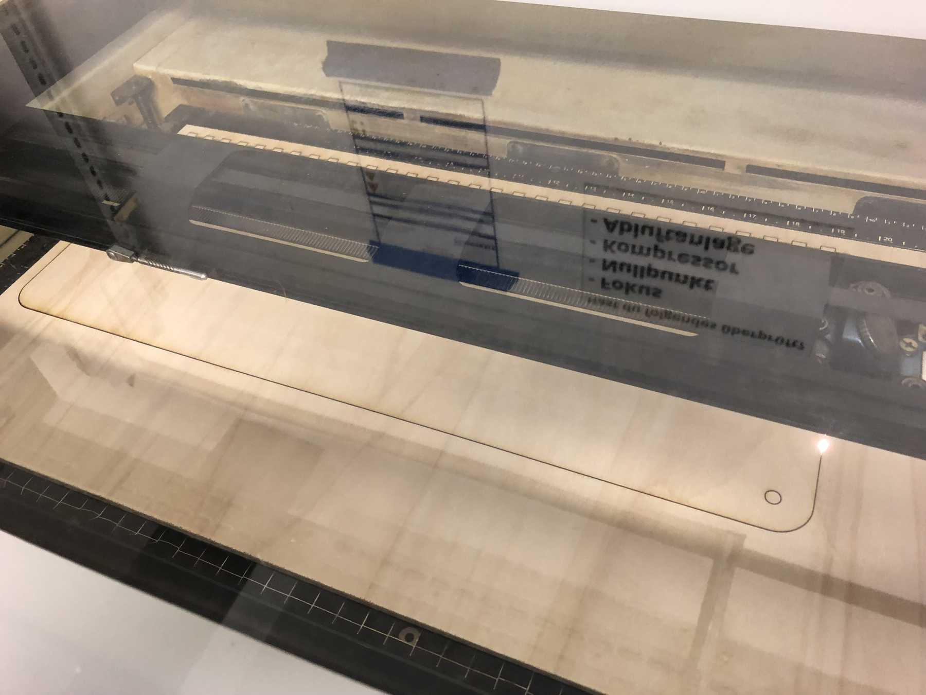


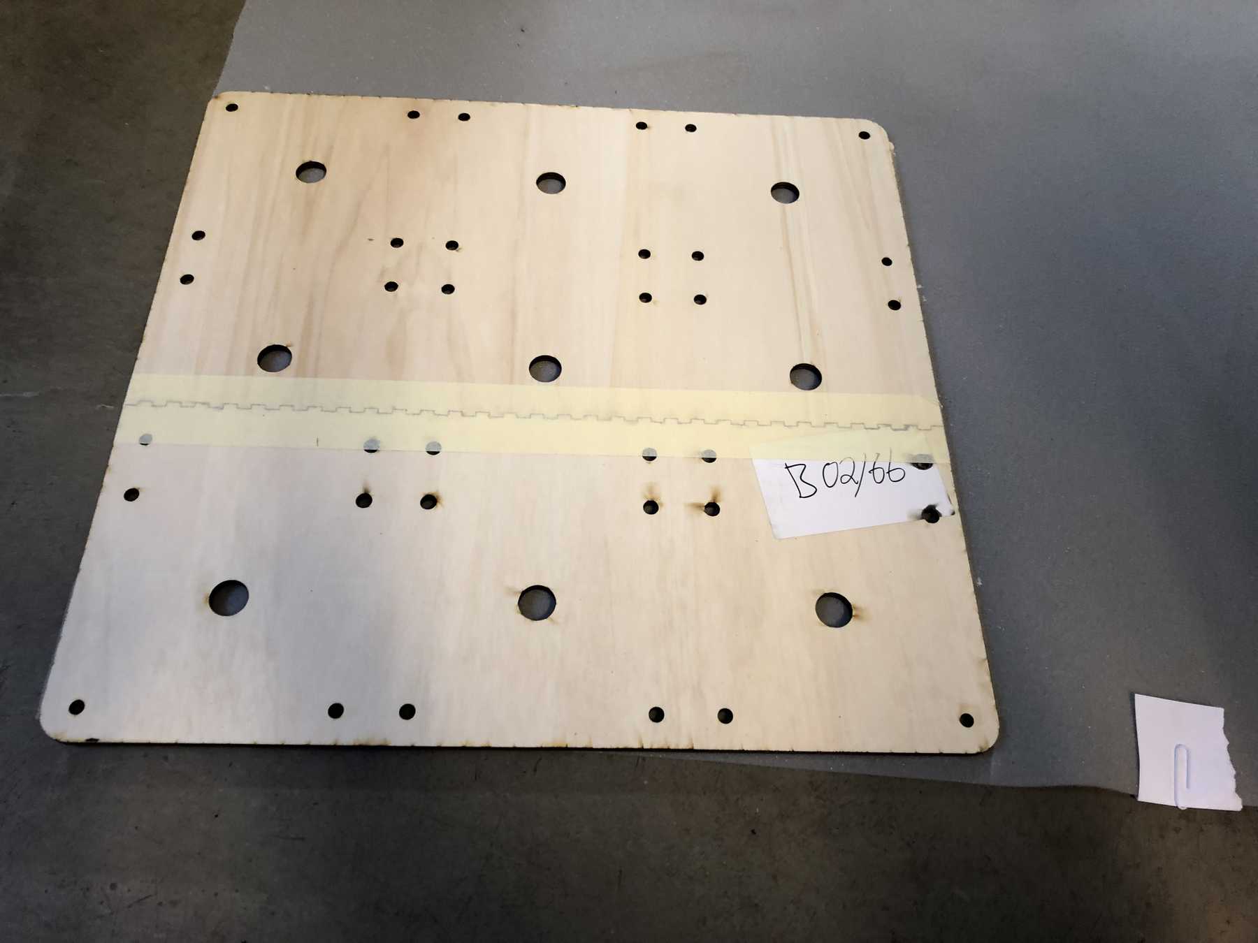
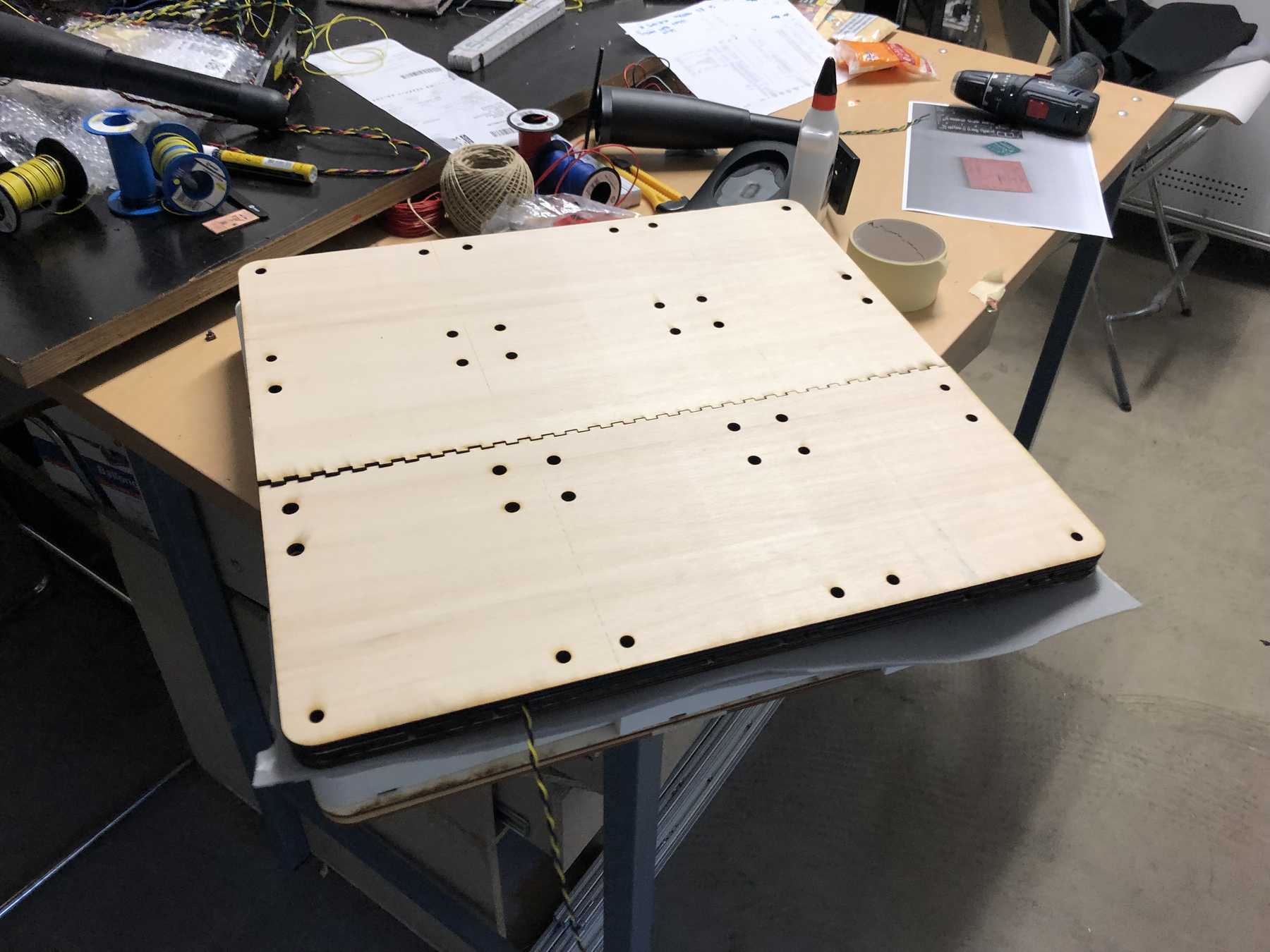

That looked good then.
Pressure mapping
First test
My chair should be individualized and tailored to my body. As a result, I thought about using conductive filament to determine the pressure on the printed surface.
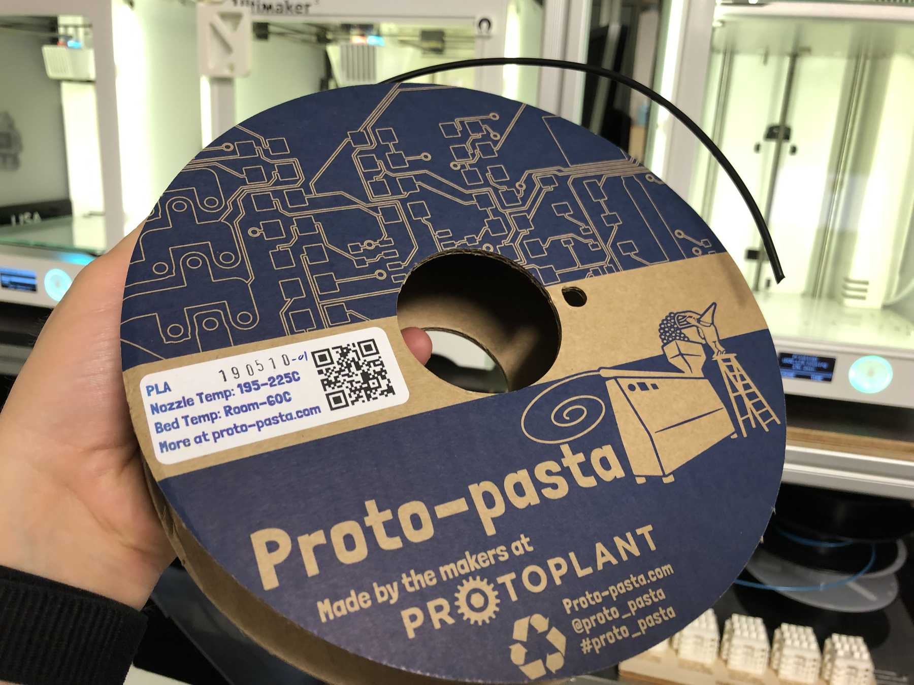
Therefore I ordered the filament from Proto-Pasta. This is a filament with the following manufacturer information regarding conductivity:
- Volume resistivity of molded resin (not 3D Printed): 15 ohm-cm
- Volume resistivity of 3D printed parts perpendicular to layers: 30 ohm-cm
- Volume resistivity of 3D printed parts through layers (along Z axis): 115 ohm-cm
- Resistance of a 10cm length of 1.75mm filament: 2-3kohm
- Resistance of a 10cm length of 2.85mm filament: 800-1200ohm
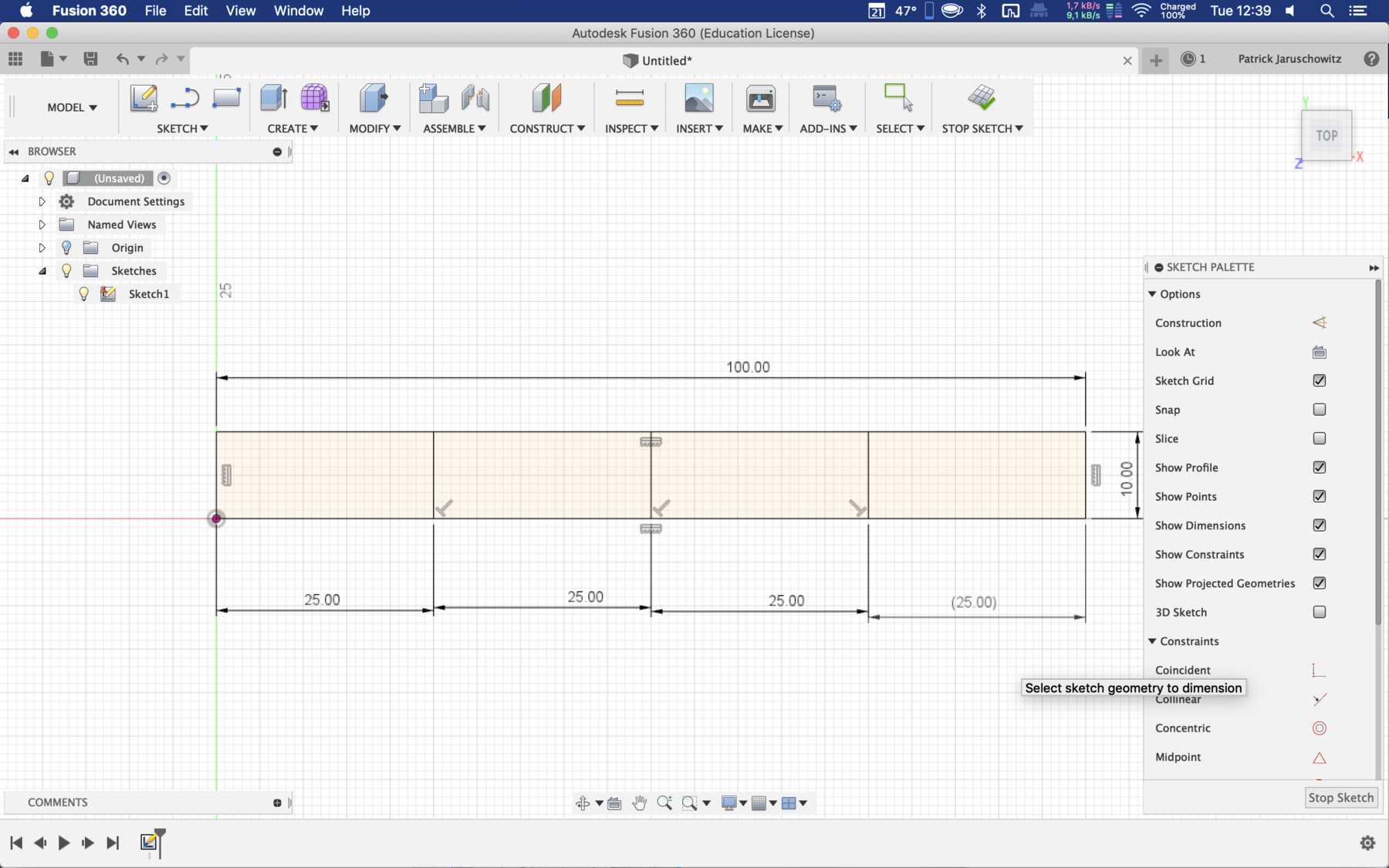
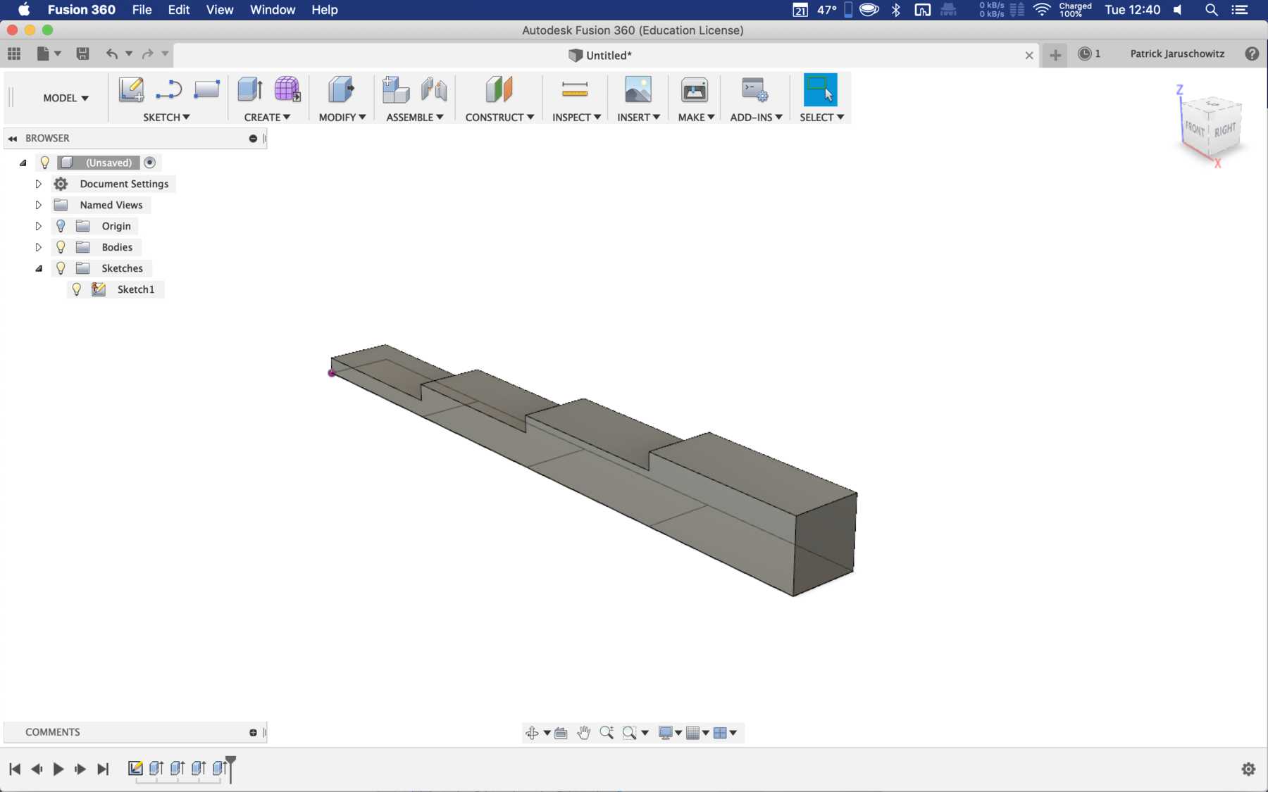
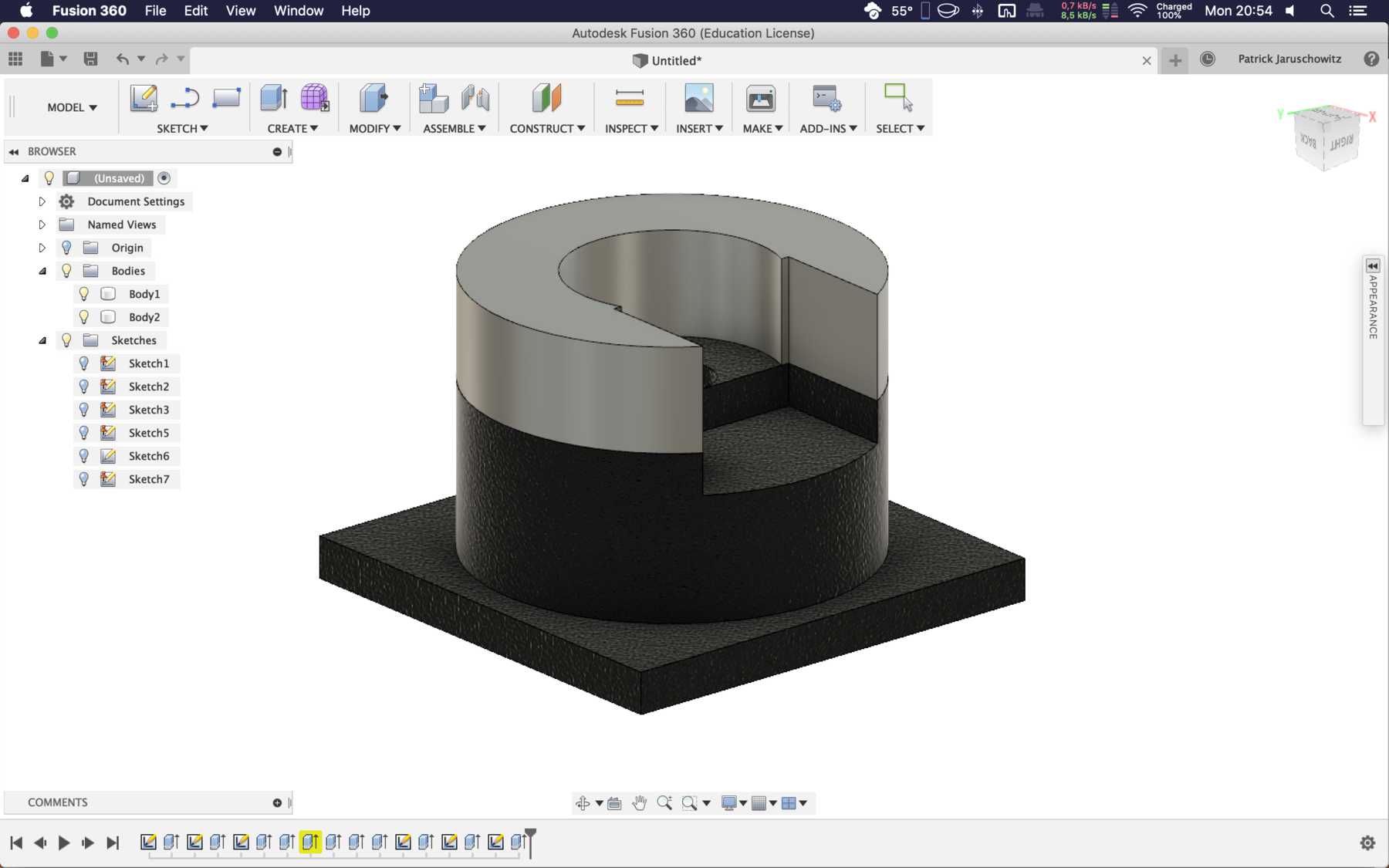
I created a test object to determine my own measurements. The object has a total length of 100mm and in 2.5mm steps a height up to 10mm. The object was created in Fusion:
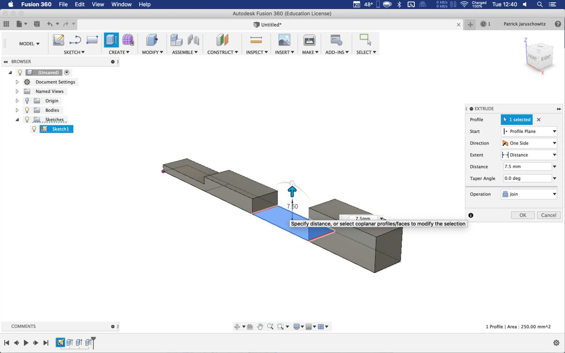
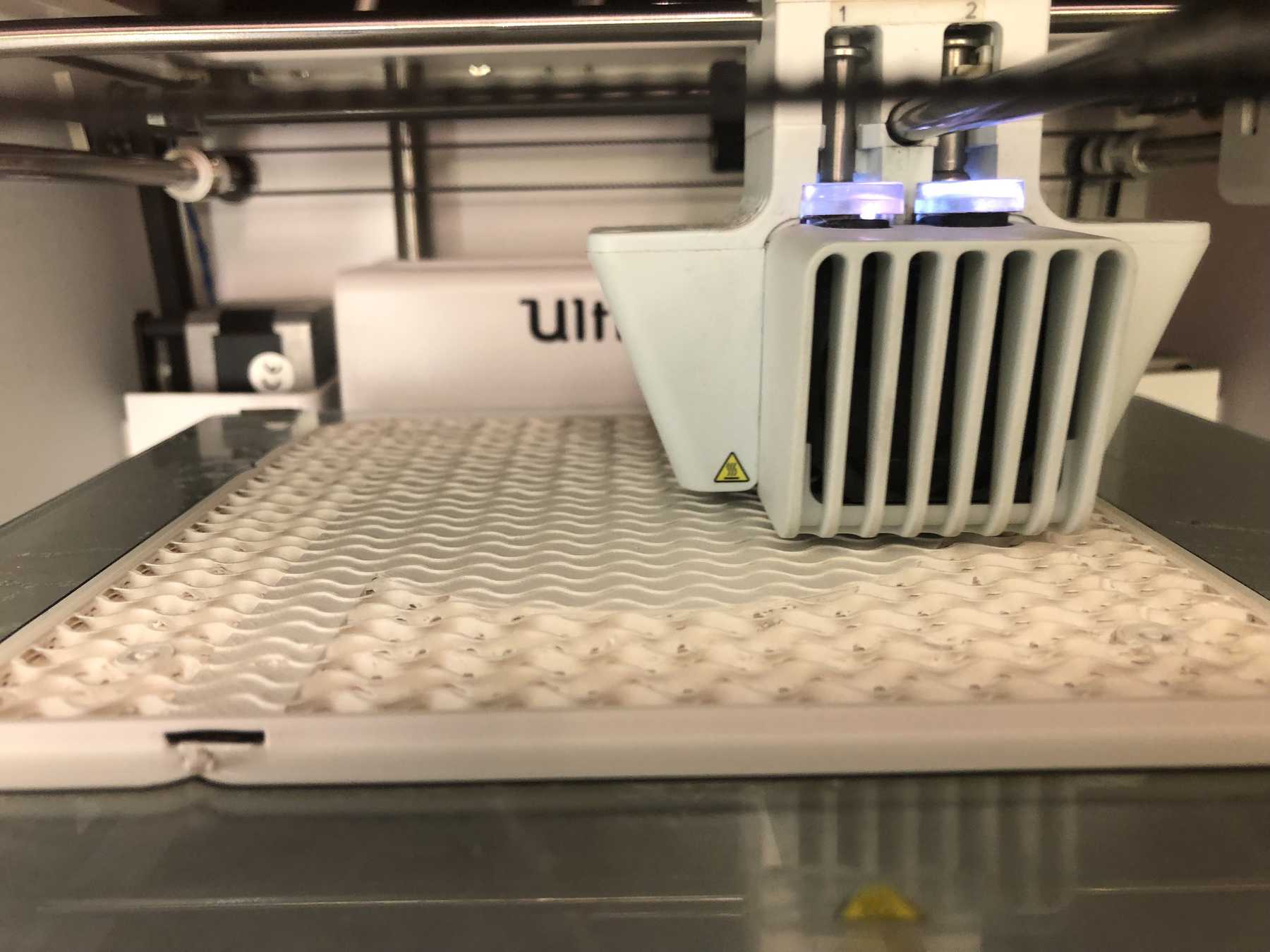
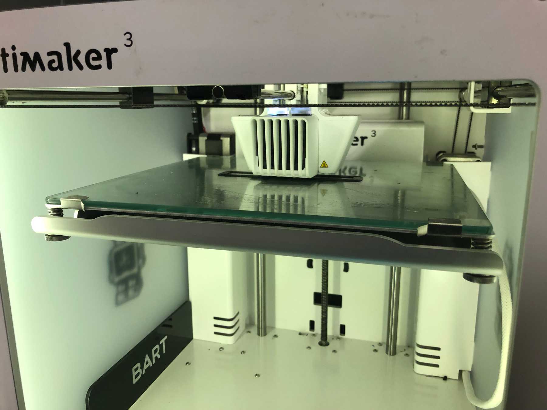
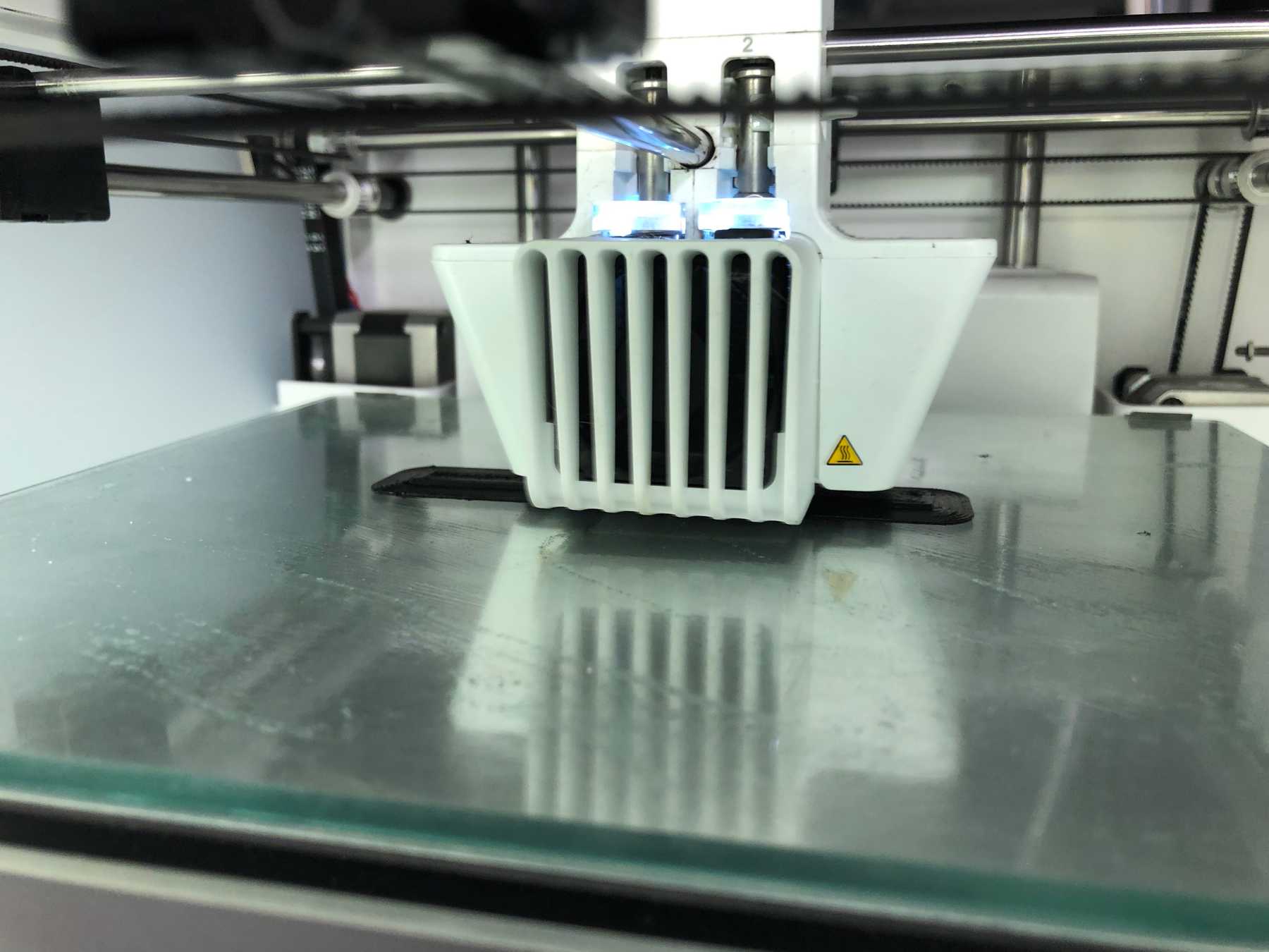
I uploaded the object to the Ultimaker 3 and started a print job. The parameters were similar to PLA, with a slight change: temperature 215°C, material flow to 90% and the bed temperature was 50°C. The adhesion of the object was excellent - partly already too good on the glass printing plate, which had Magigoo as additional adhesive.

Next, I wanted to determine the resistance of the printed object and see which range we were actually in:
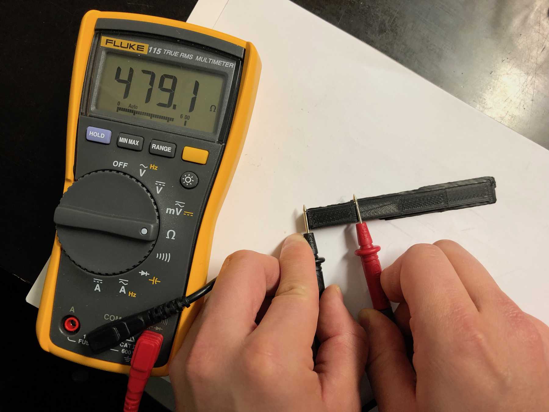
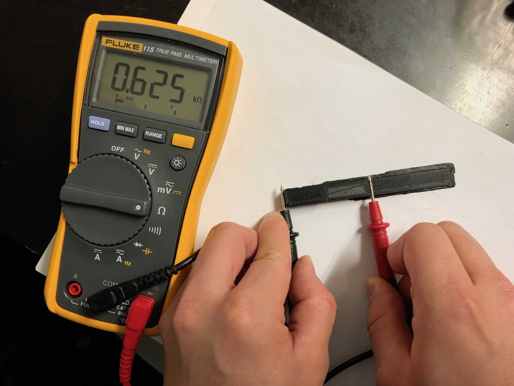

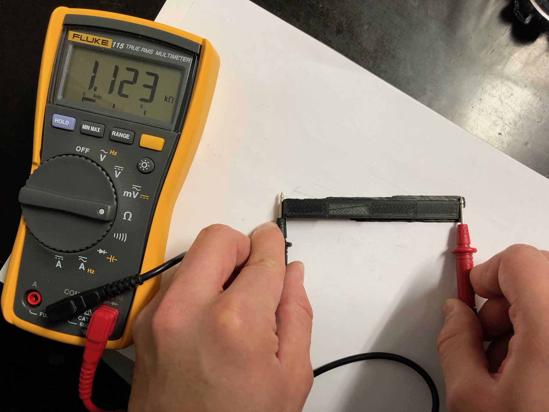
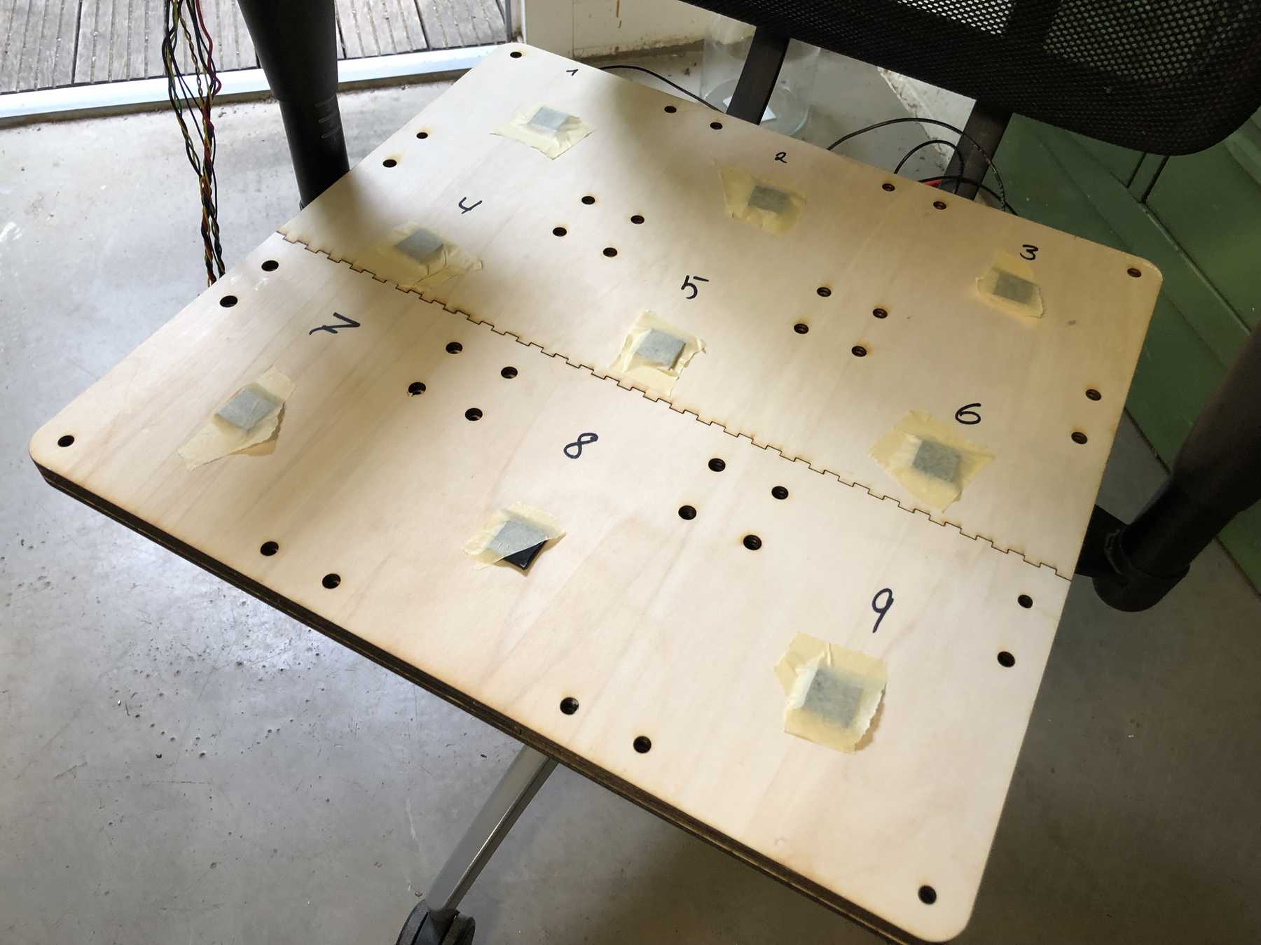
So far, it looks pretty good. Then the first tests and comparisons with copper foils should be carried out. For this purpose, individual plates were printed out and compared with each other. The copper foil was glued onto an acrylic glass plate. I also used the Velostat foil to draw comparisons and to try out different variants.
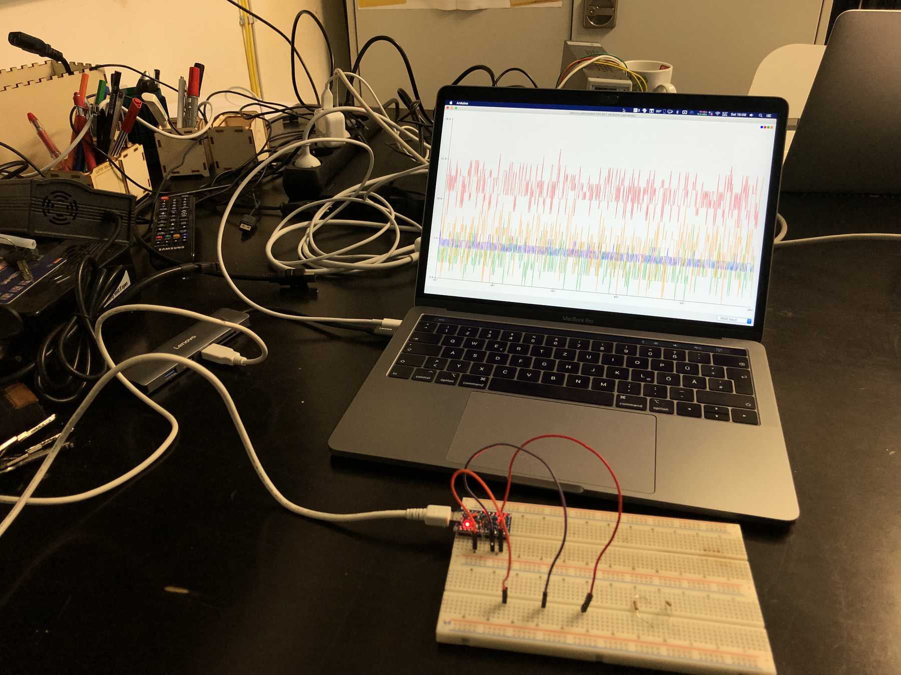
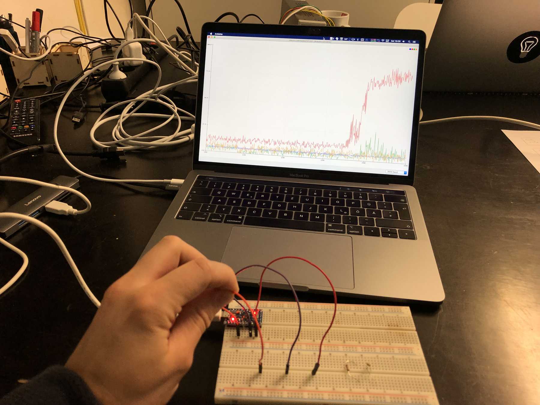


I tried different libraries, but also the integrated touch sensors of the individual microcontrollers. For example CapapacitiveSensor or Adafruit_FreeTouch.
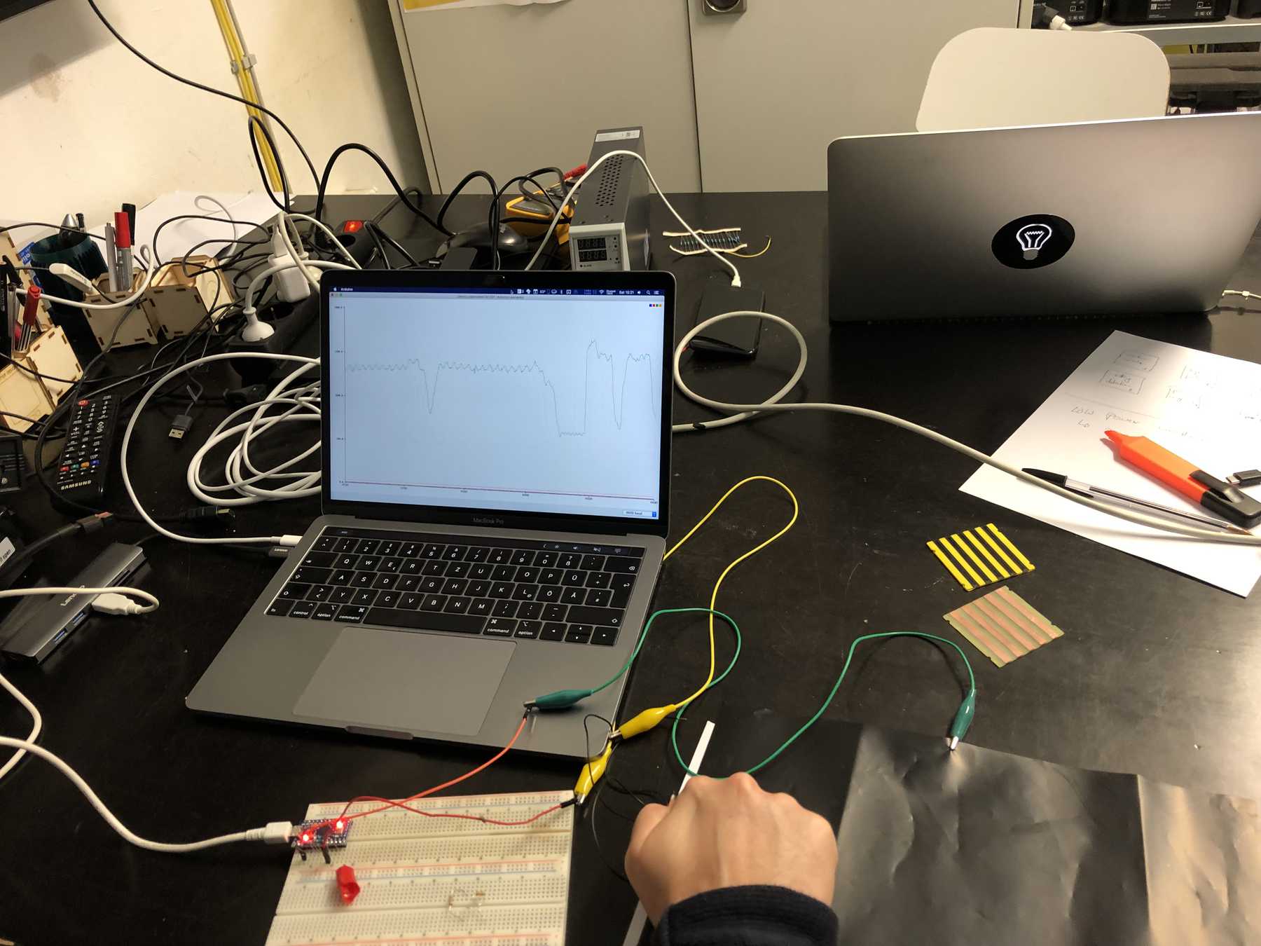
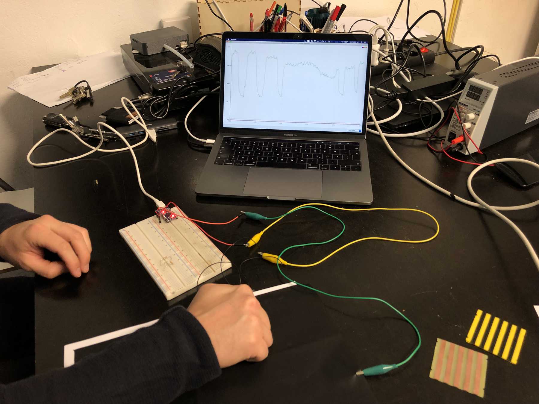
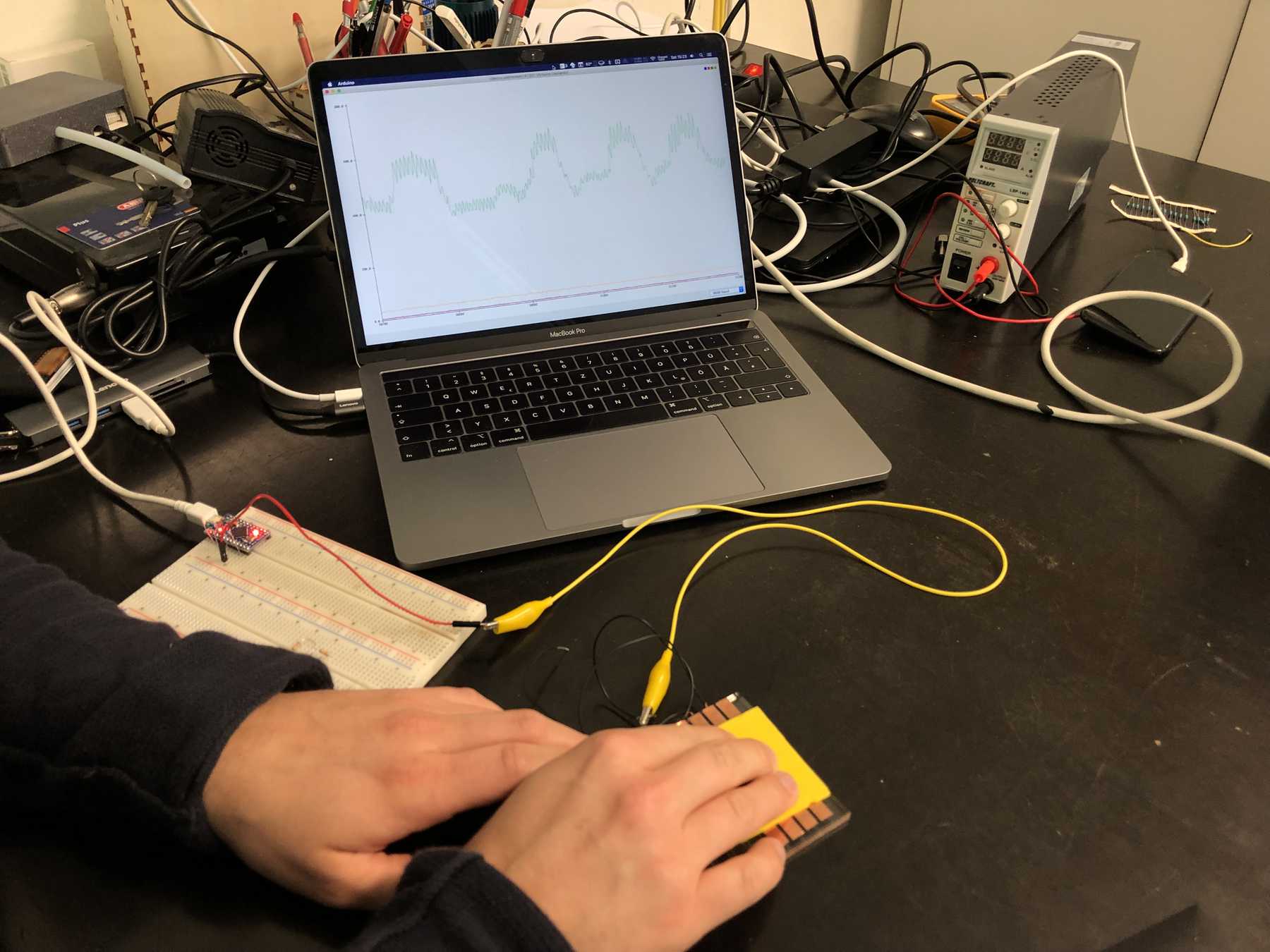
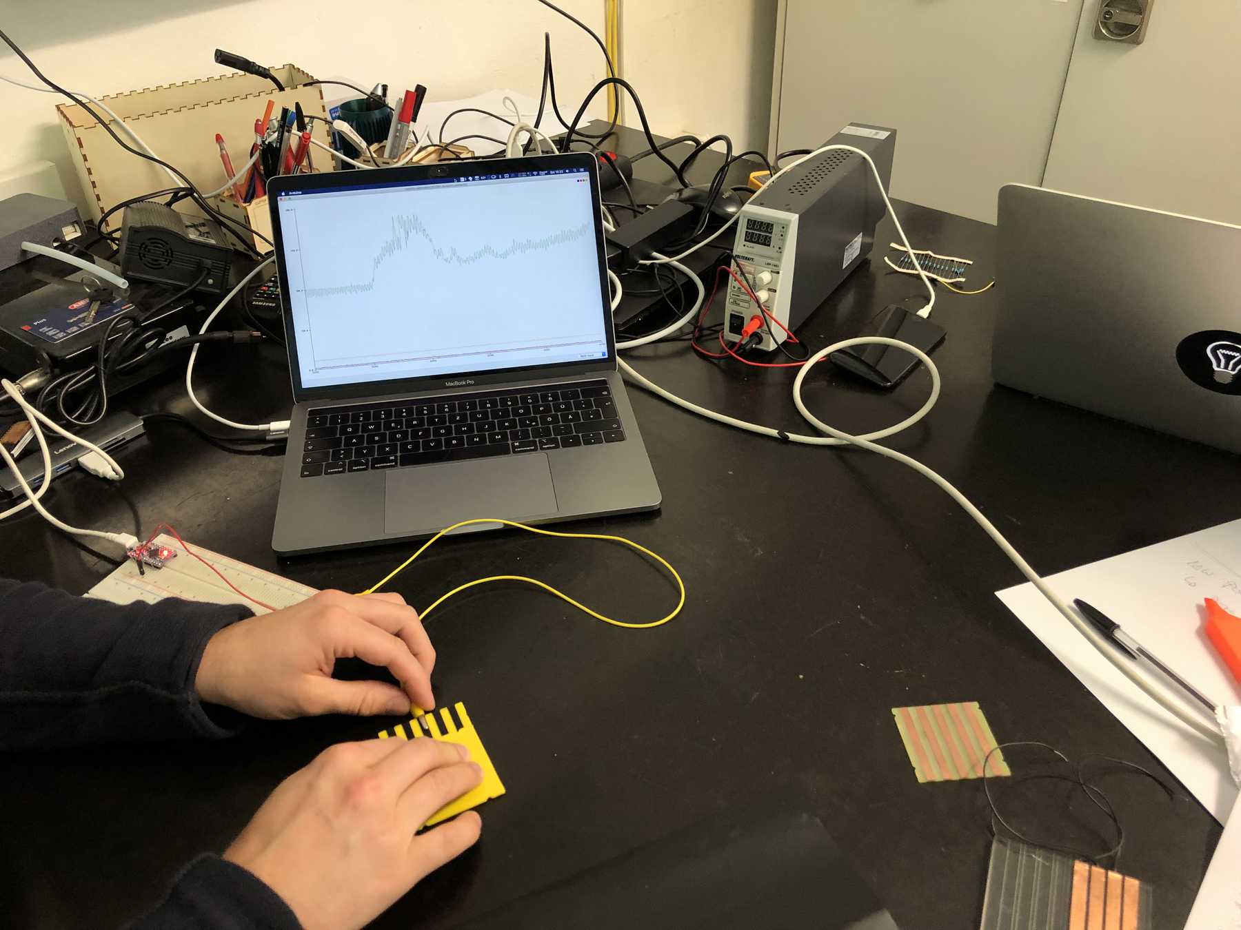
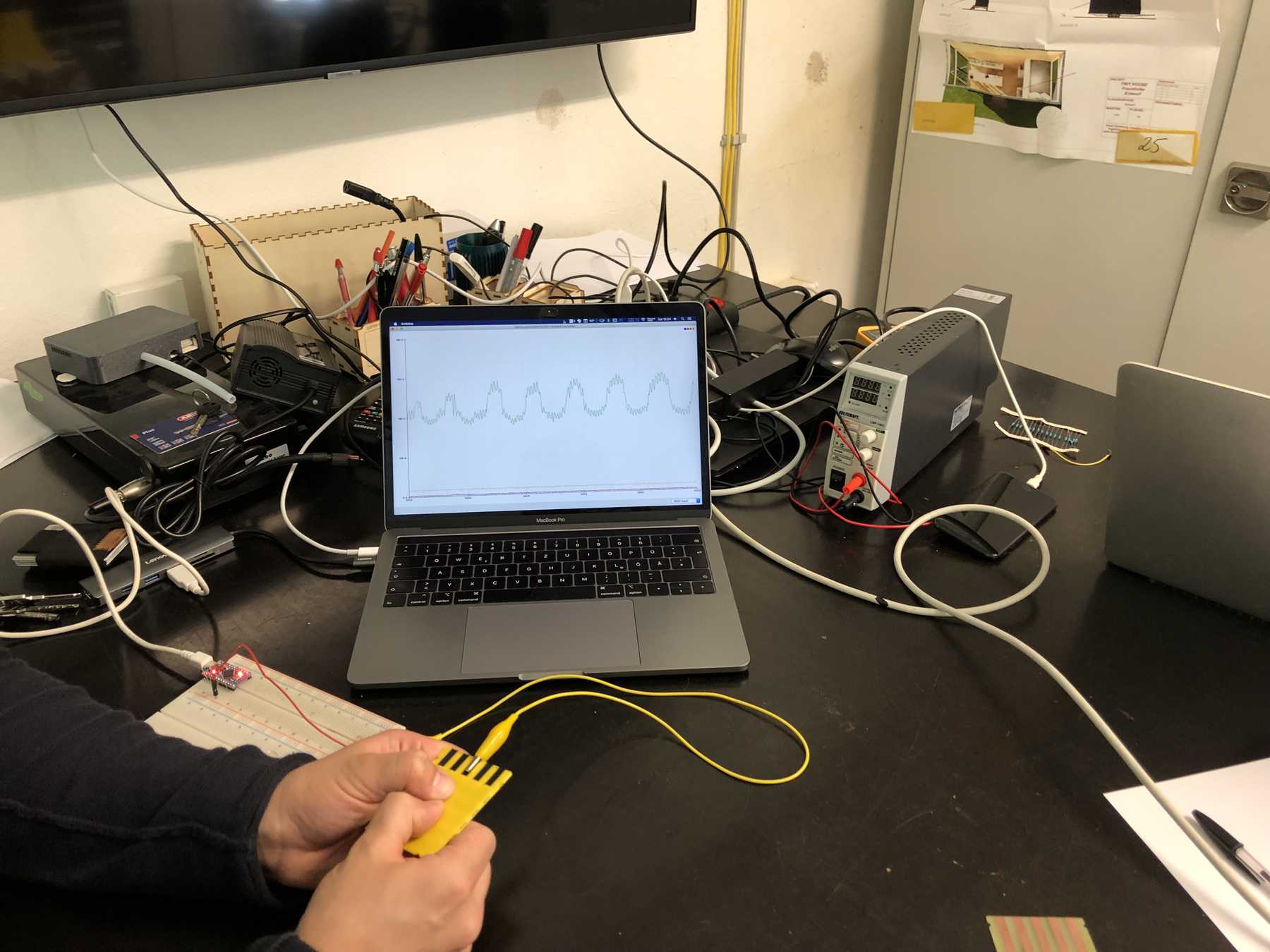
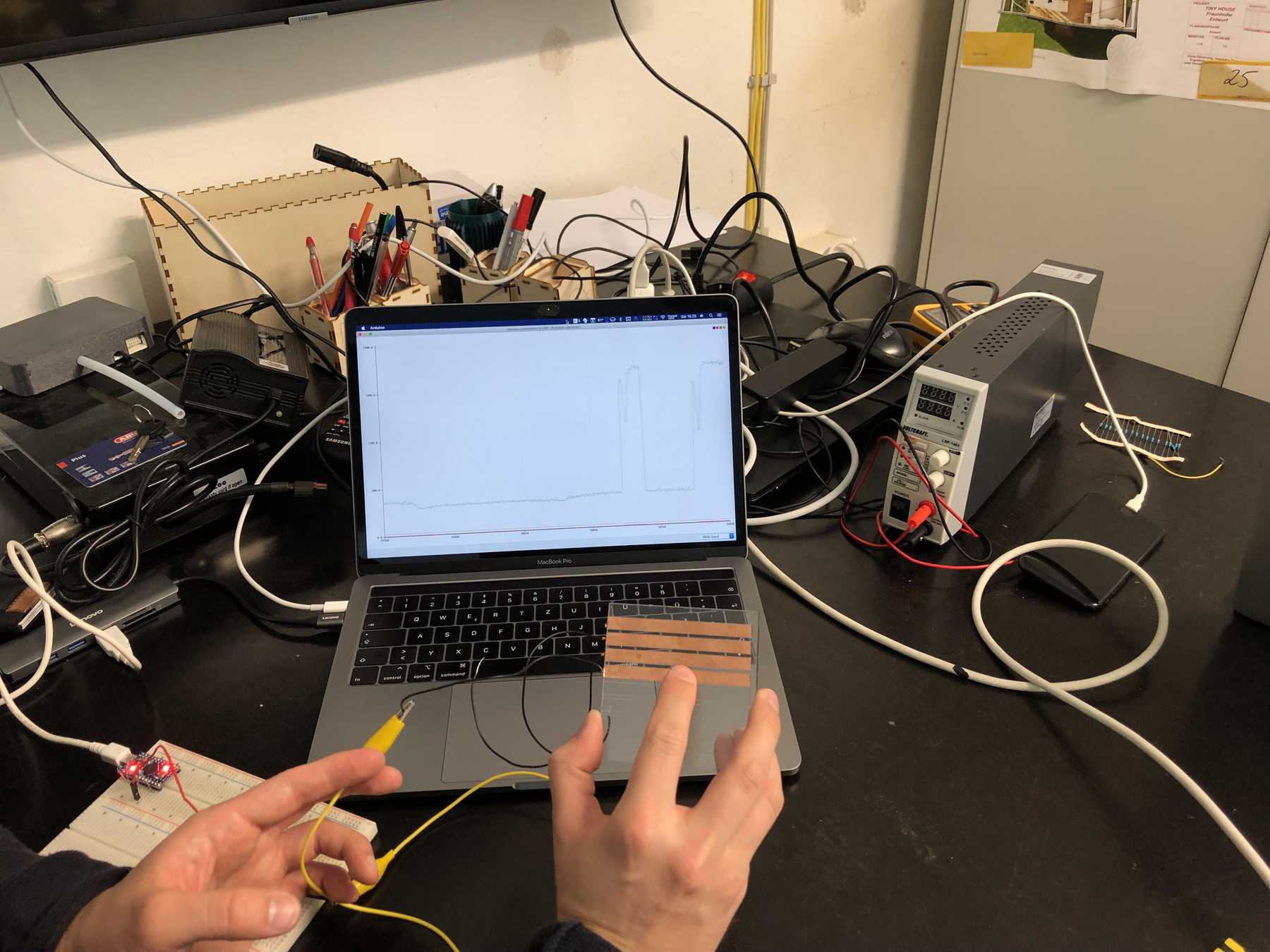
The result was this:
- Printed conductive filament is suitable for capacitive pressure determination.
- The noise can be significantly reduced by an additional ground connection.
- The areas of the touch sensor should be kept as small as possible.
- A much better SNR (Signal Noise Ratio) was achieved by adding several resistors. At 5 MOhm the result was excellent.
I would like to mention more objective measurements and more concrete numbers. Unfortunately, there is no time for this.
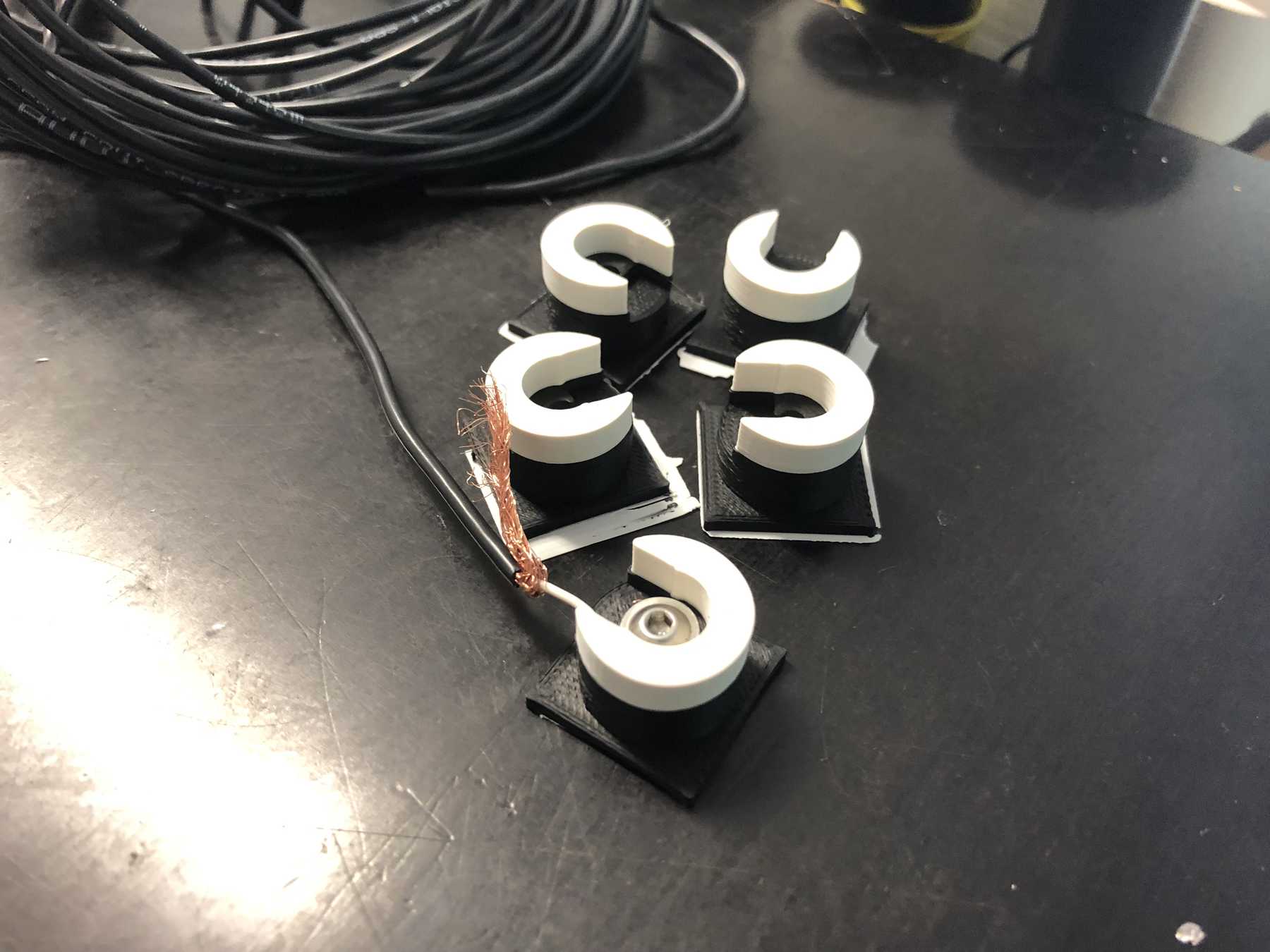
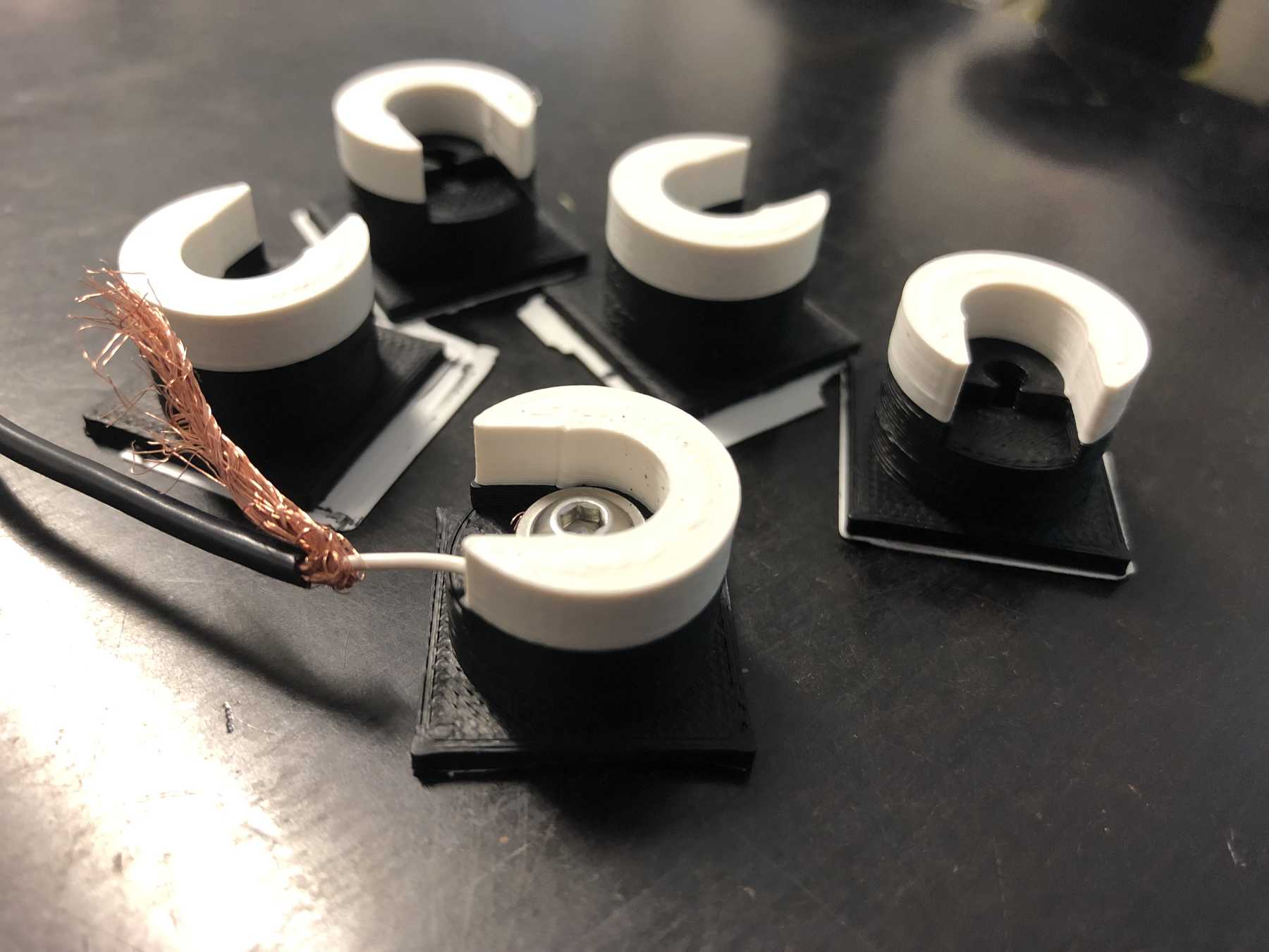
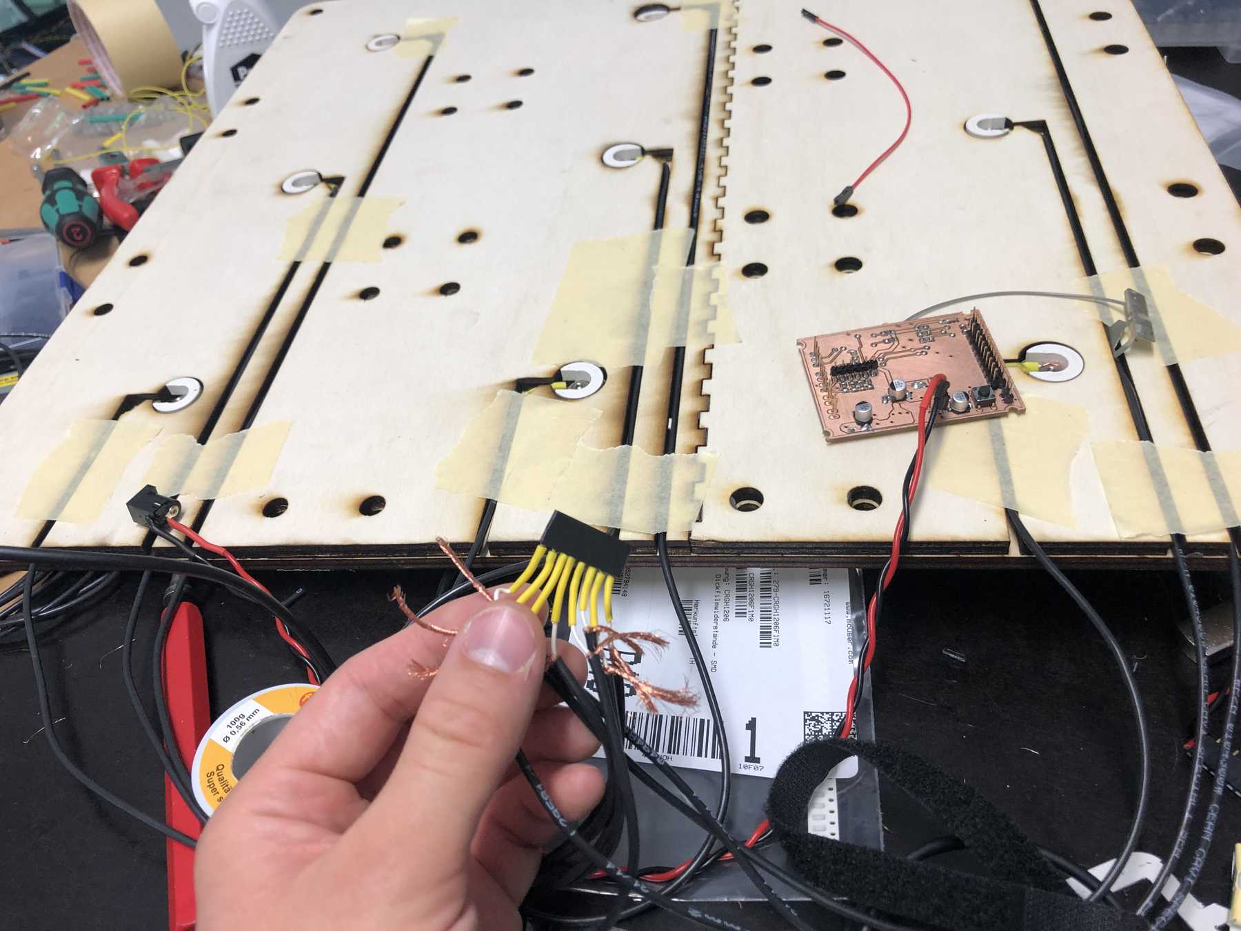
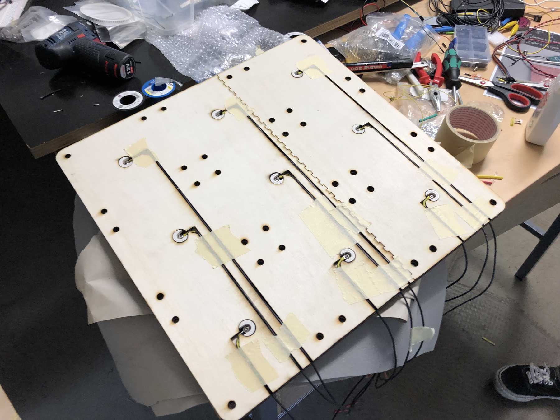
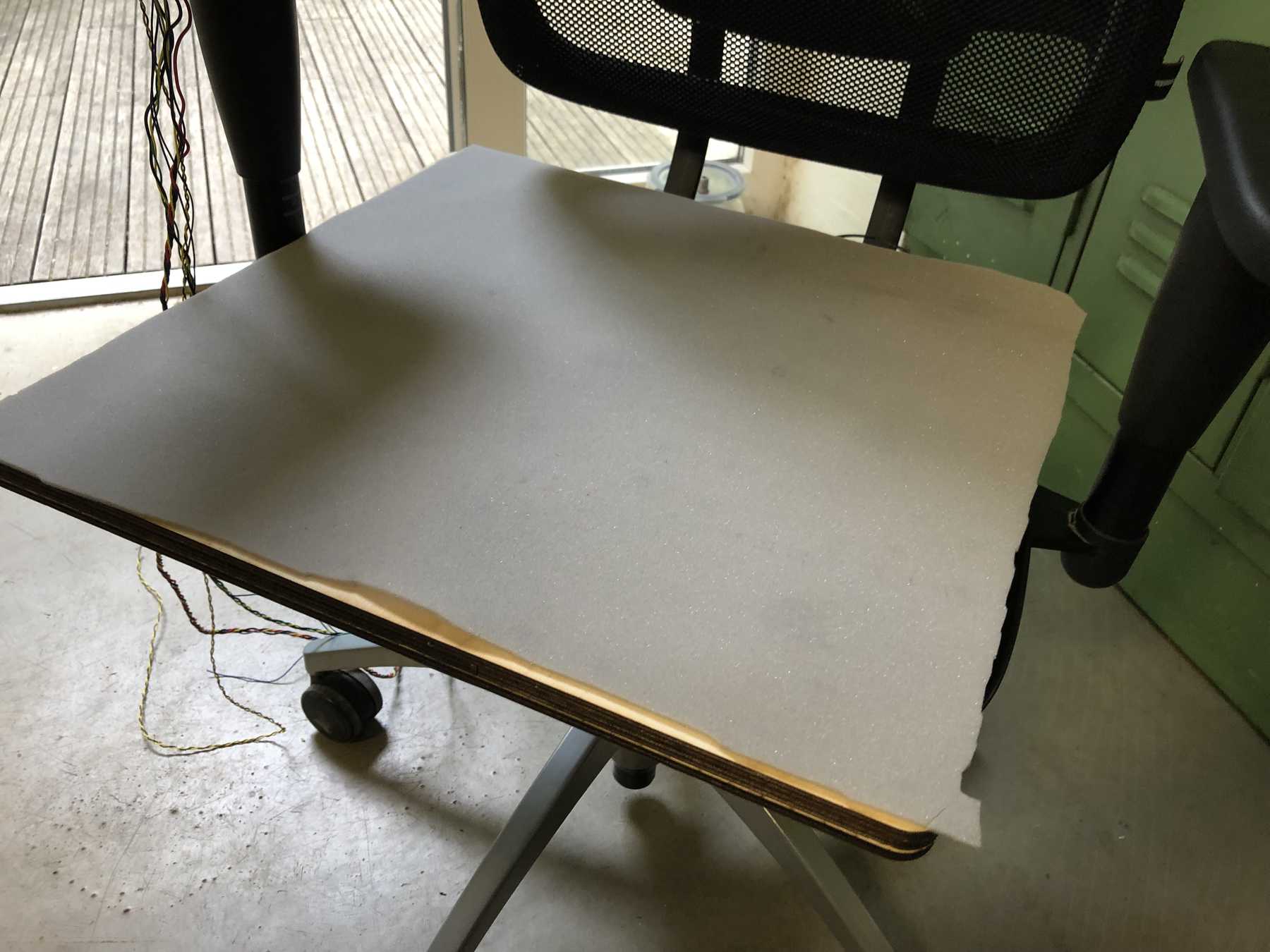
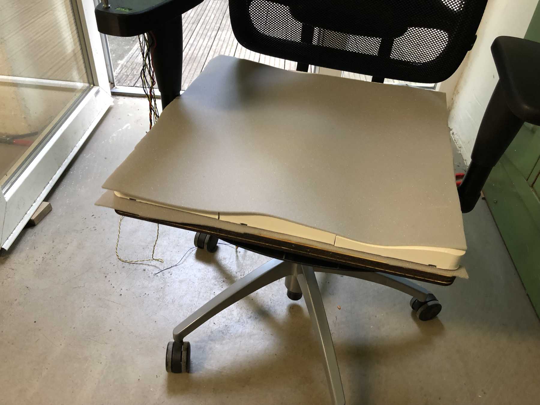
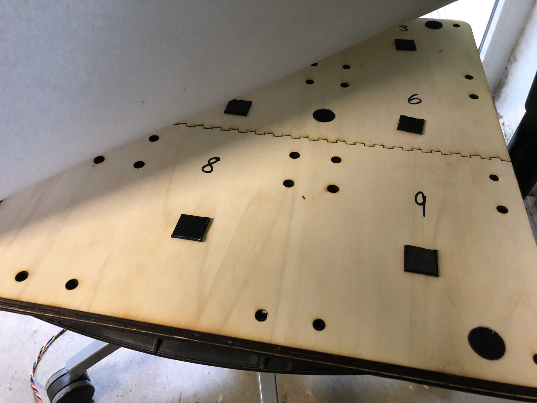
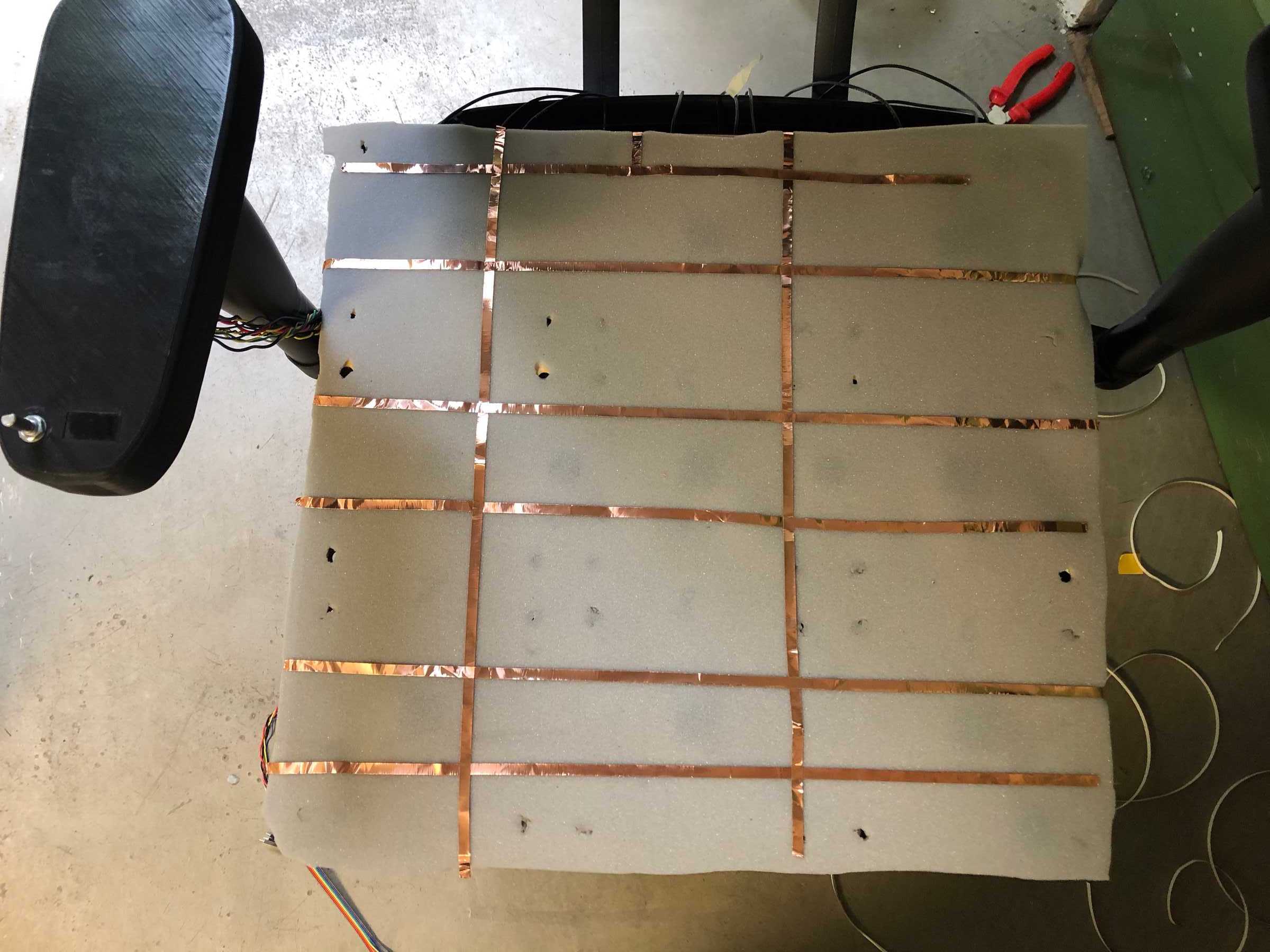
The next step was to create the model, which would later fit to the base plate. Between the two conductive filaments a foam layer of 3mm should be put. This ensures that we get more sensitive values. The capacitive sensor then looked as follows:
The cable was connected to the filament with a screw.
Electronics
PCB Design
My final project should be based on the ESP32. It contains 10 touch sensors, of which only 8 were available at the end. One is dropped because it’s attached to the internal memory of the built-in flash and the other one suddenly didn’t work anymore with the final board. But this worked on all previous test boards. Otherwise, there were always problems with the board, so I tend to dissuade this microcontroller for the next project. But in the beginning it was the egg-laying wollmilchsau - with WLAN, fast clock rate, enough memory and interrupt pins. Countless Arduino libraries have also been adapted for the ESP32 so far.
The final board should contain the following input and output sensors and requires the following number of connectors:
| Amount | Functions | VCC | GND | MCU PINS | GPIO Amount |
|---|---|---|---|---|---|
| 1 | Encoder with Push Putton | x | x | DIGITAL IN | 3 |
| 1 | Vibration | x | x | DIGITAL OUT | 1 |
| 1 | SD CARD | x | x | SPI (CS,MOSI,MISO,SCK) | 4 |
| 1 | Display | x | x | I2C (SCL,SDA) | 2 |
| 8 | Capacitive Pads | x | x | DIGITALS INs & OUT | 8 |
The vibration motor had the following specifications from Adafruit: https://www.adafruit.com/product/1201
- Dimension: 10mm diameter, 2.7mm thick
- Voltage: 2V - 5V
- 5V current draw: 100mA, 4V current draw: 80mA, 3V current draw: 60mA, 2V current draw: 40mA
- 11000 RPM at 5V
- Weight: 0.9 gram
The MicroSD card had the following connectors: https://www.conrad.de/de/p/microsd-kartensockel-druck-druck-attend-112i-tdar-r-1-st-1308329.html
- Height: 5.2 mm
- Operating temperature: -40 ~ +85c
- Rated current: 0.5a per pin
- Rated Voltage: 1.8 V
- Technology: Ddr 2
The display is an SSD1306 with 128x64 pixels: https://cdn-shop.adafruit.com/datasheets/SSD1306.pdf
- Viewing angle : greater than 160 degrees
- Low power consumption : 0.04W during normal operation
- Support wide voltage : 3.3V-5V DC
- Driver IC : SSD1306
- Communication : IIC, only two I / O ports
- Backlight : OLED self light, no backlight
- 4 pin version
The rotary encoder was found in the FabLab. It was a version with push button function. It has 24 steps and looks like this model. https://www.sparkfun.com/products/9117
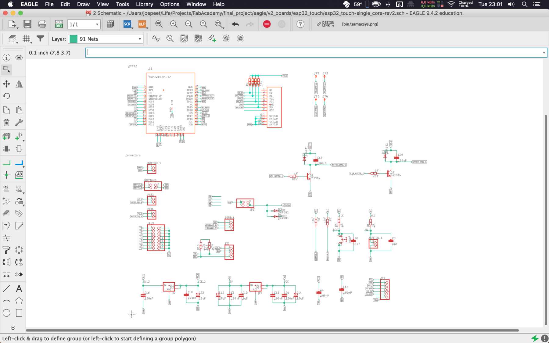
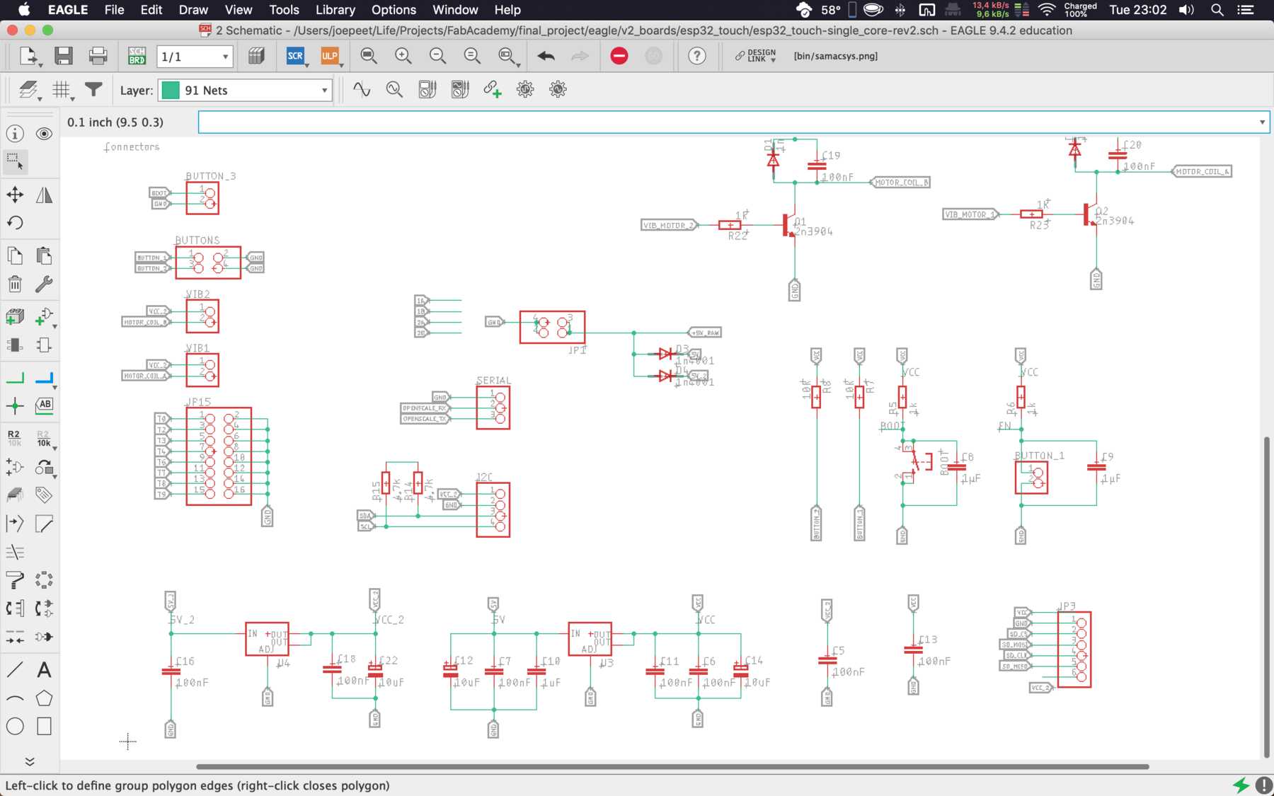
Then I started with the individual drawings with EAGLE. My first final should also contain different further functions, which were systematically thrown out.
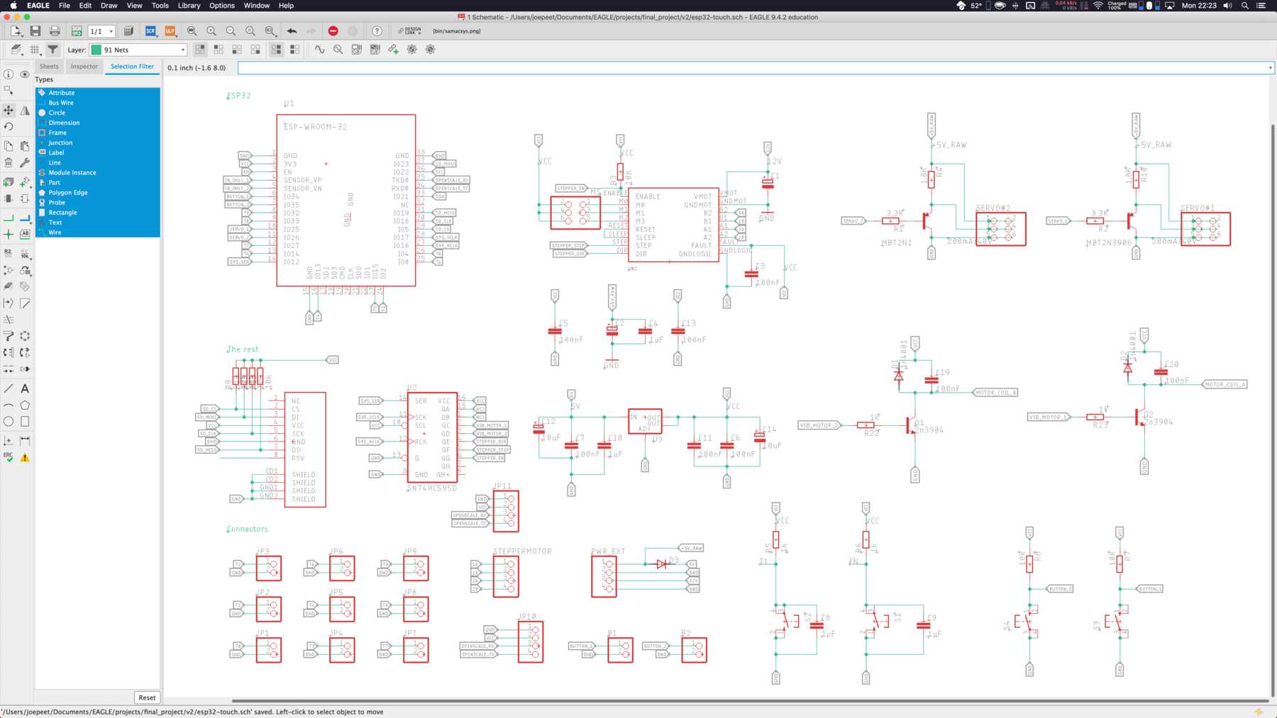
Various iterations followed, so that the schematic drawing looked as follows:

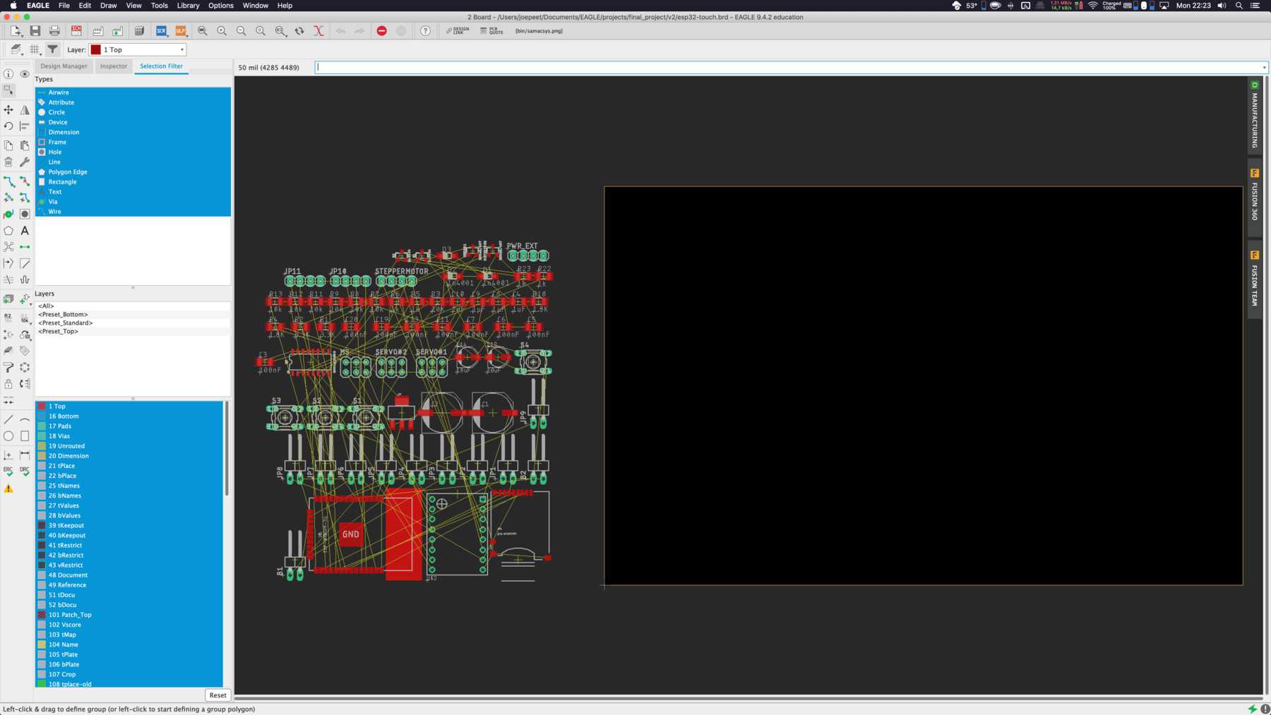
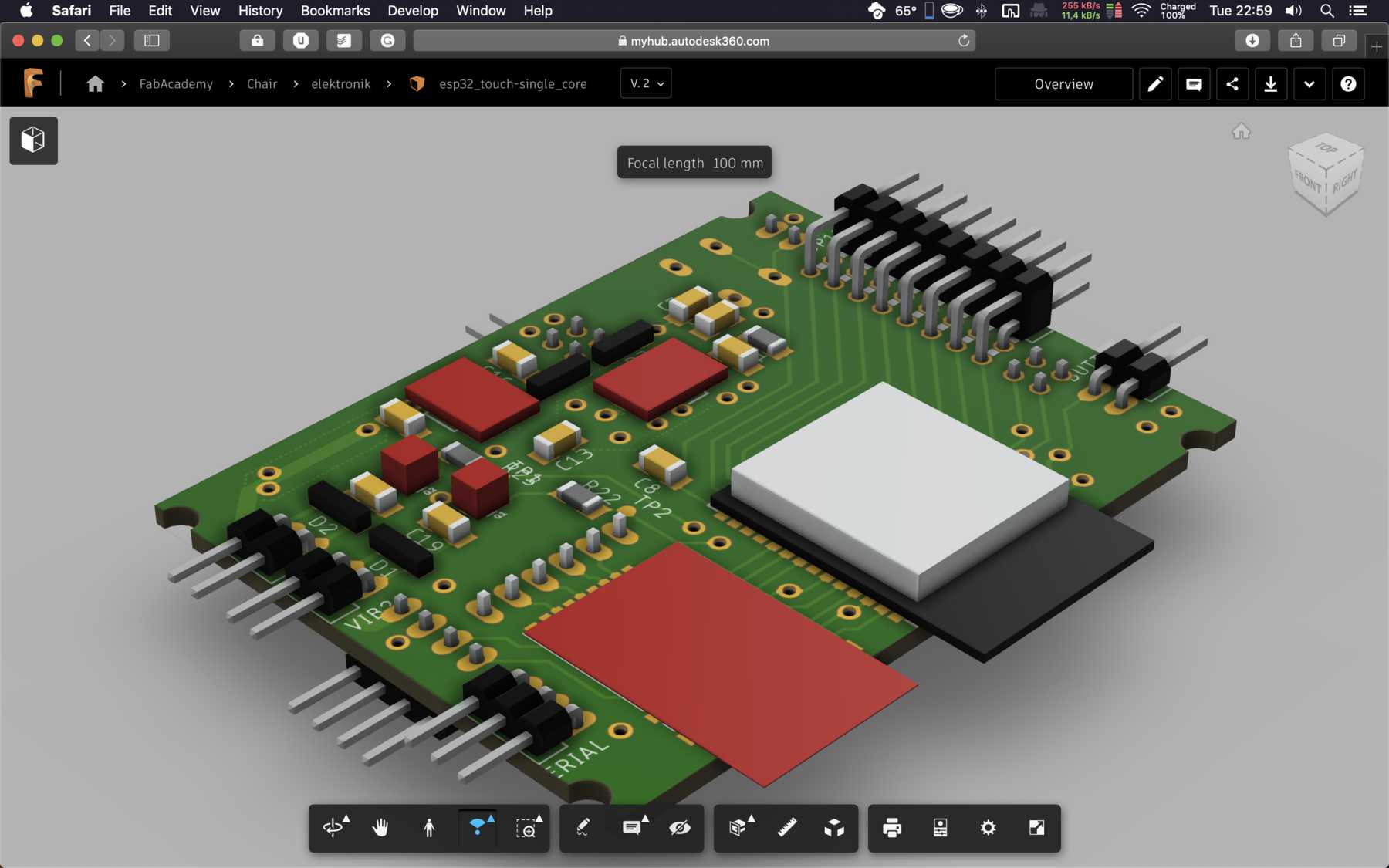
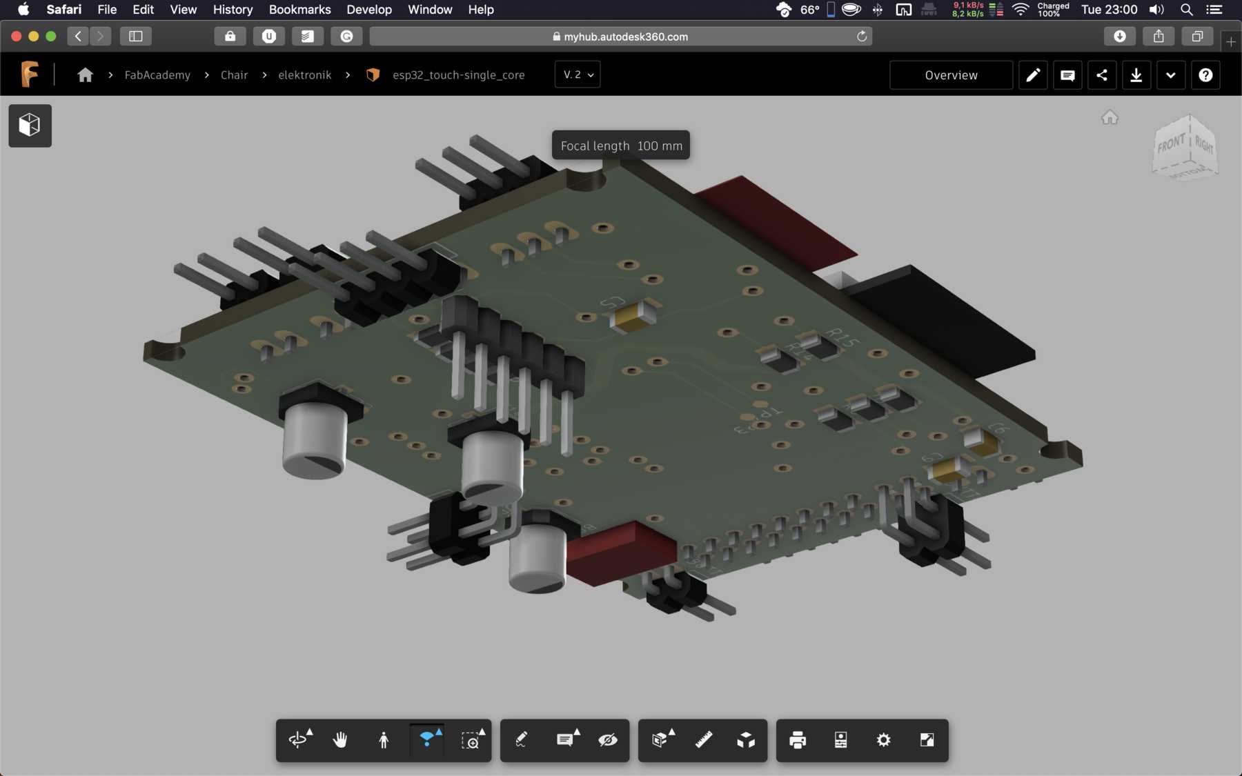
The final board design was as follows:
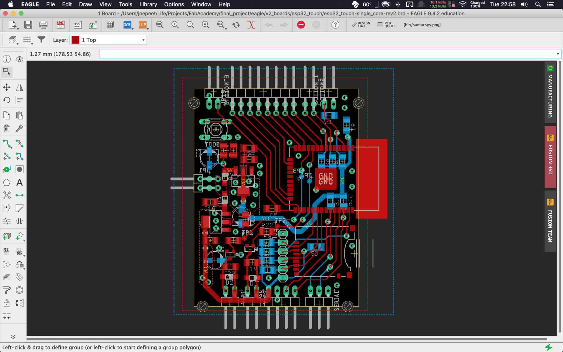
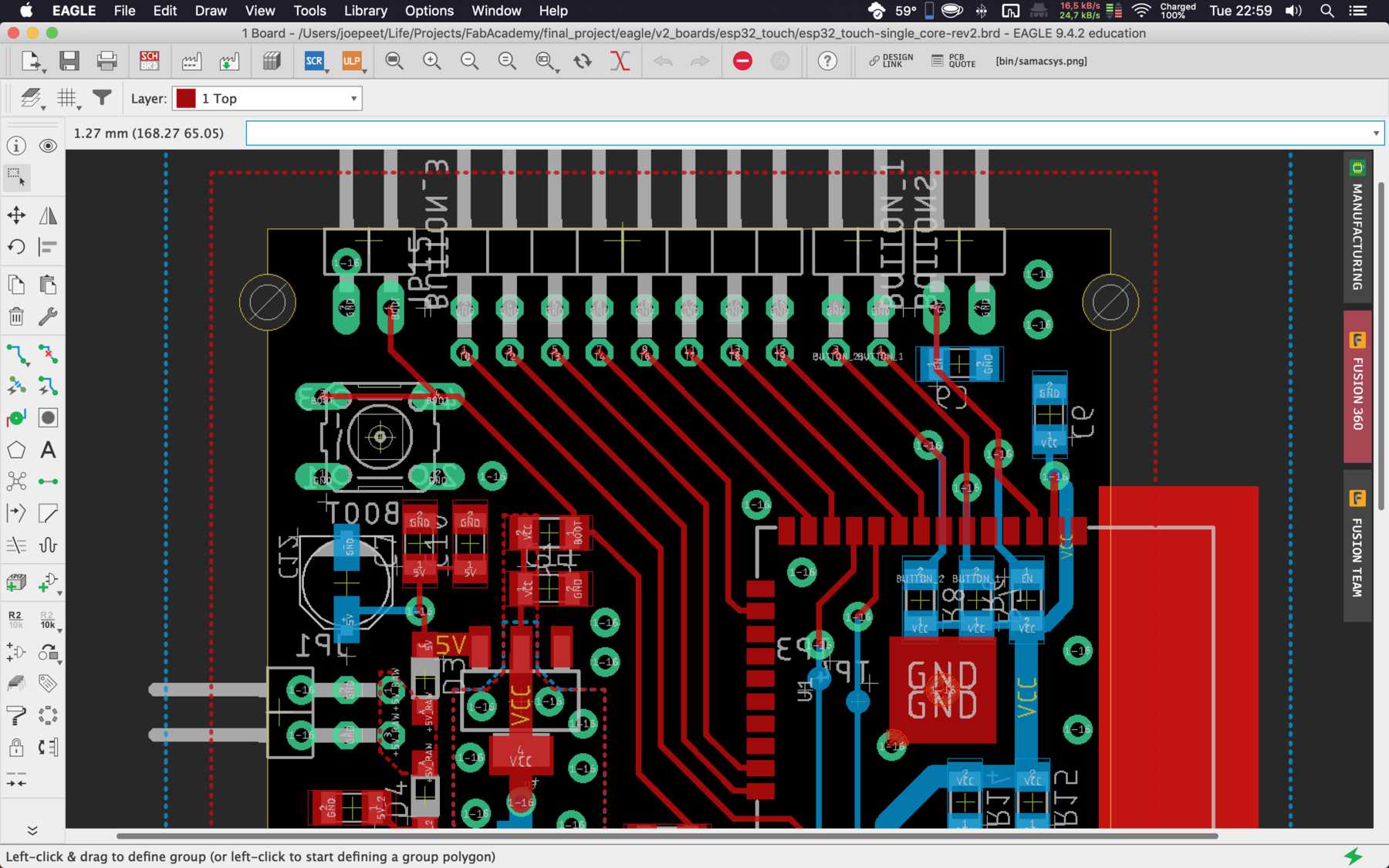
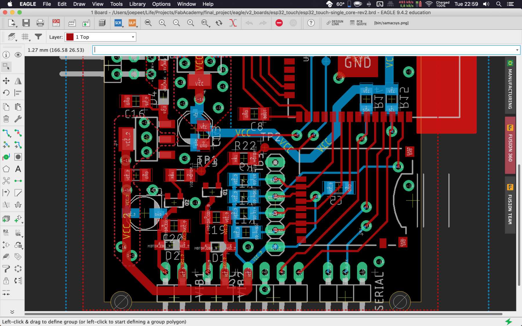
The preview of the board was a pleasure.
In the end the following parts were necessary:
| Qty | Value | Device | Package | Parts | Description | |
|---|---|---|---|---|---|---|
| 1 | 10-XX | B3F-10XX | BOOT | OMRON SWITCH | ||
| 4 | PINHD-1X2/90 | 1X02/90 | BUTTON_1, BUTTON_3, VIB1, VIB2 | PIN HEADER | ||
| 1 | PINHD-1X3/90 | 1X03/90 | SERIAL | PIN HEADER | ||
| 1 | PINHD-1X4/90 | 1X04/90 | I2C | PIN HEADER | ||
| 1 | PINHD-1X6 | 1X06 | JP3 | PIN HEADER | ||
| 2 | PINHD-2X2/90 | 2X02/90 | BUTTONS, JP1 | PIN HEADER | ||
| 1 | PINHD-2X8/90 | 2X08/90 | JP15 | PIN HEADER | ||
| 2 | V_REG_LM1117SOT223 | SOT223 | U3, U4 | Voltage Regulator LM1117 | ||
| 4 | 100nF | C-EUC1206 | C1206 | C5, C13, C19, C20 | CAPACITOR, European symbol | |
| 5 | 100nF | C-EUC1206 | C1206 | C6, C7, C11, C16, C18 | CAPACITOR, European symbol | |
| 6 | 10k | R-EU_R1206 | R1206 | R7, R8, R9, R11, R12, R13 | RESISTOR, European symbol | |
| 3 | 10uF | CPOL-EUC | PANASONIC_C | C12, C14, C22 | POLARIZED CAPACITOR, European symbol | |
| 2 | 1k | R-EU_R1206 | R1206 | R22, R23 | RESISTOR, European symbol | |
| 2 | 1k | R-EU_R1206 | R1206 | R5, R6 | RESISTOR, European symbol | |
| 4 | 1n4001 | DIODE-SOD123 | SOD123 | D1, D2, D3, D4 | DIODE | |
| 1 | 1uF | C-EUC1206 | C1206 | C10 | CAPACITOR, European symbol | |
| 2 | 1µF | C-EUC1206 | C1206 | C8, C9 | CAPACITOR, European symbol | |
| 2 | 2n3904 | TRANS_NPN-MMBT2222AL | SOT23-3 | Q1, Q2 | NPN transistor | |
| 2 | 4,7k | R-EU_R1206 | R1206 | R14, R15 | RESISTOR, European symbol | |
| 1 | ESP-WROOM-32 | ESP-WROOM-32 | ESP-WROOM-32 | U1 | ||
| 4 | TPB1,27 | TPB1,27 | B1,27 | TP1, TP2, TP3, TP4 | Test pad | |
| 1 | USD-SOCKETUSD | USD-SOCKETUSD | USD-SOCKET-PP | U$1 | microSD Socket |
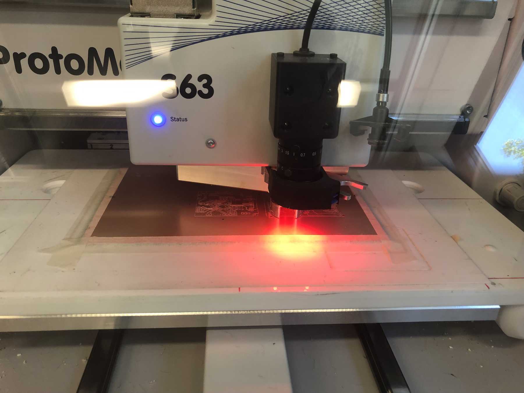
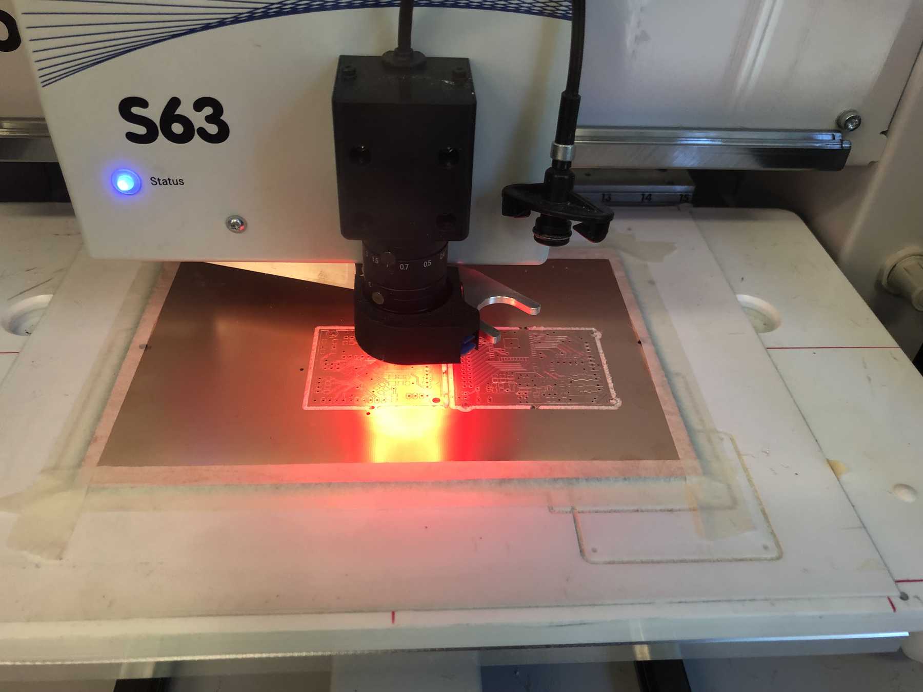
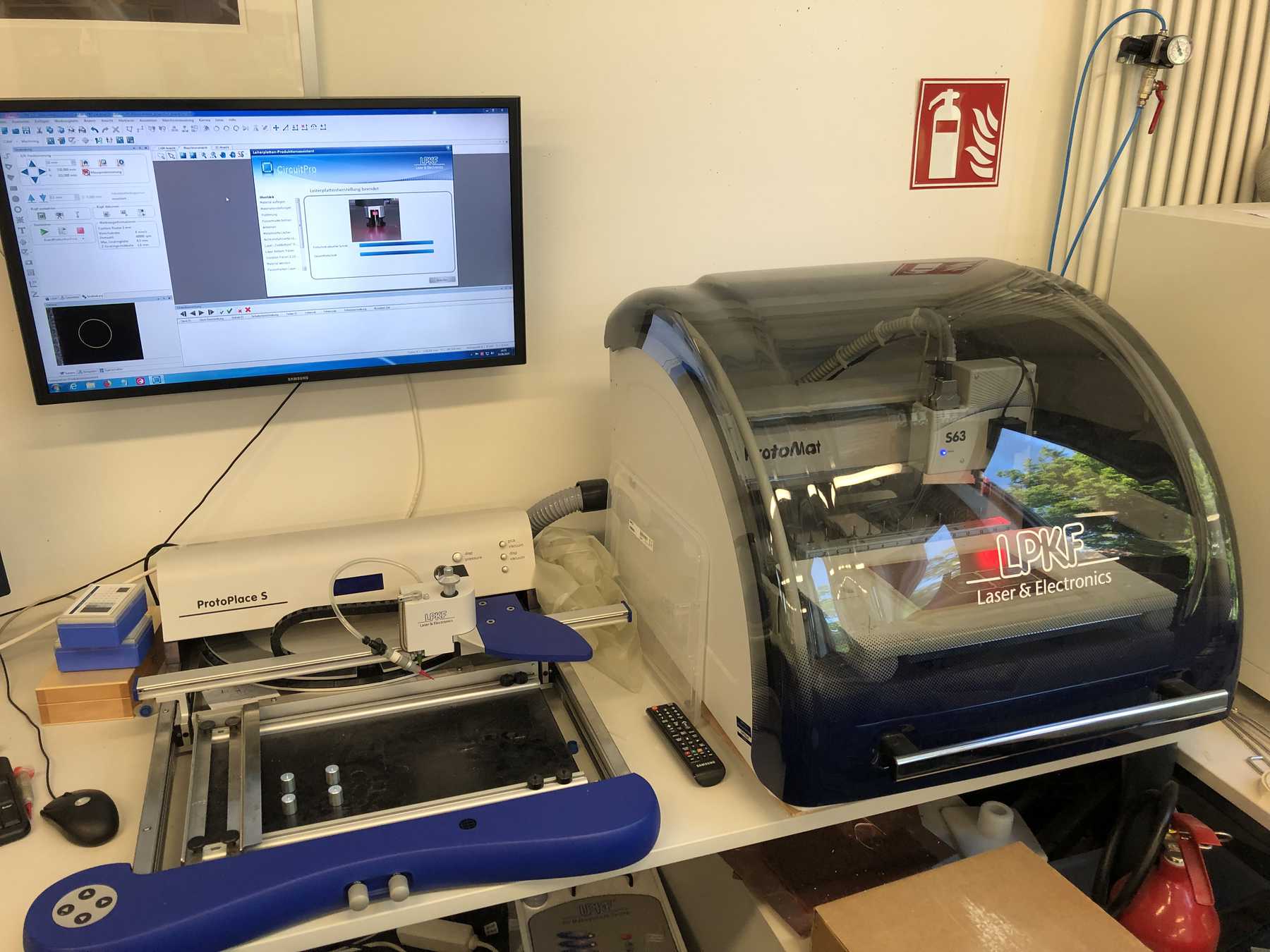
PCB production
Go to LKPF ProtoMat S63 for milling. A pleasure. I have already uploaded countless videos about this machine. Therefore here only a few pictures of the process.
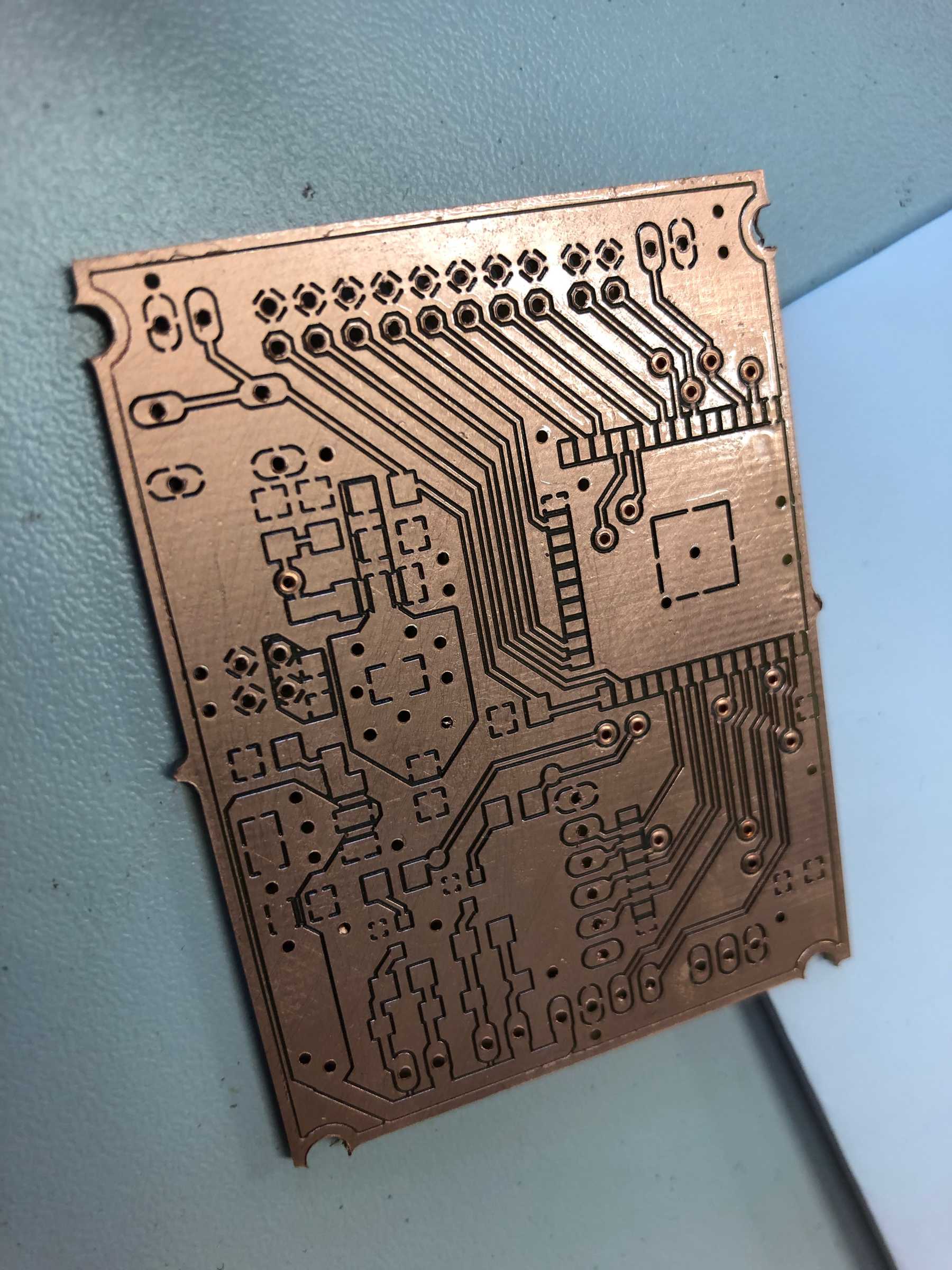
- Milling.
- Solder varnish on it.
- Vias through connections.
- A nice board.


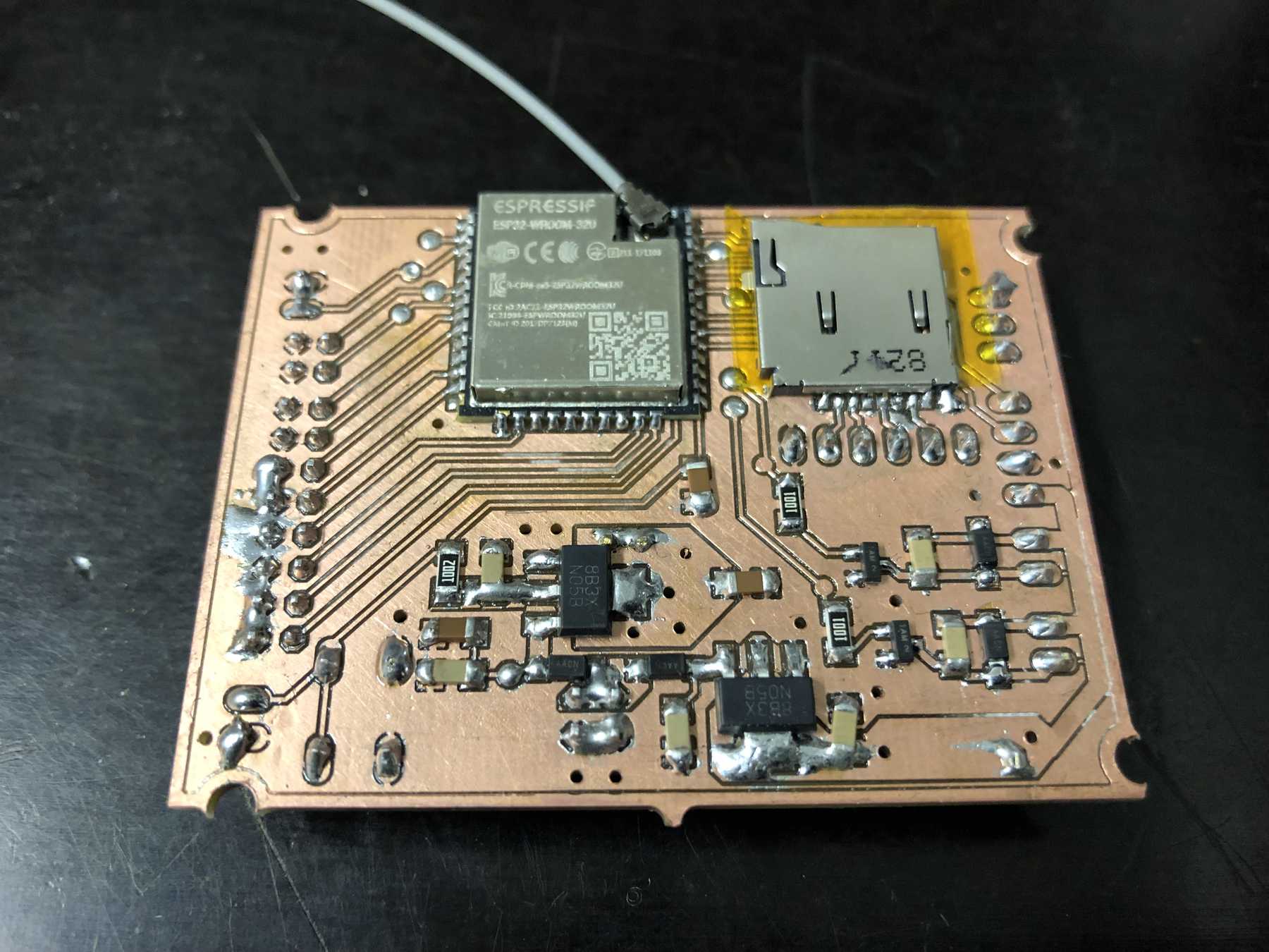
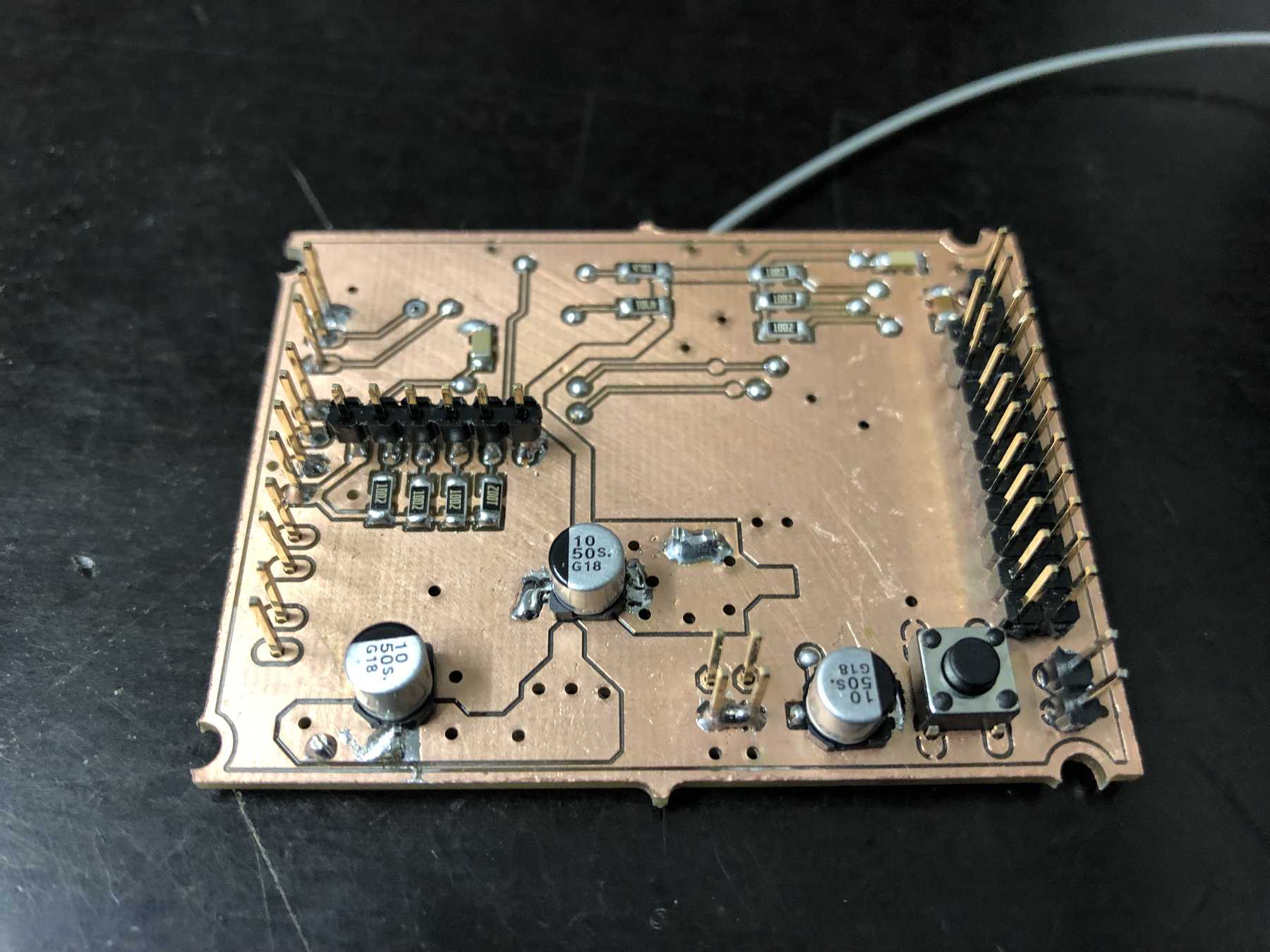
Soldering
Then it went on to soldering in chaos, which in the meantime has arisen with all previous developments.
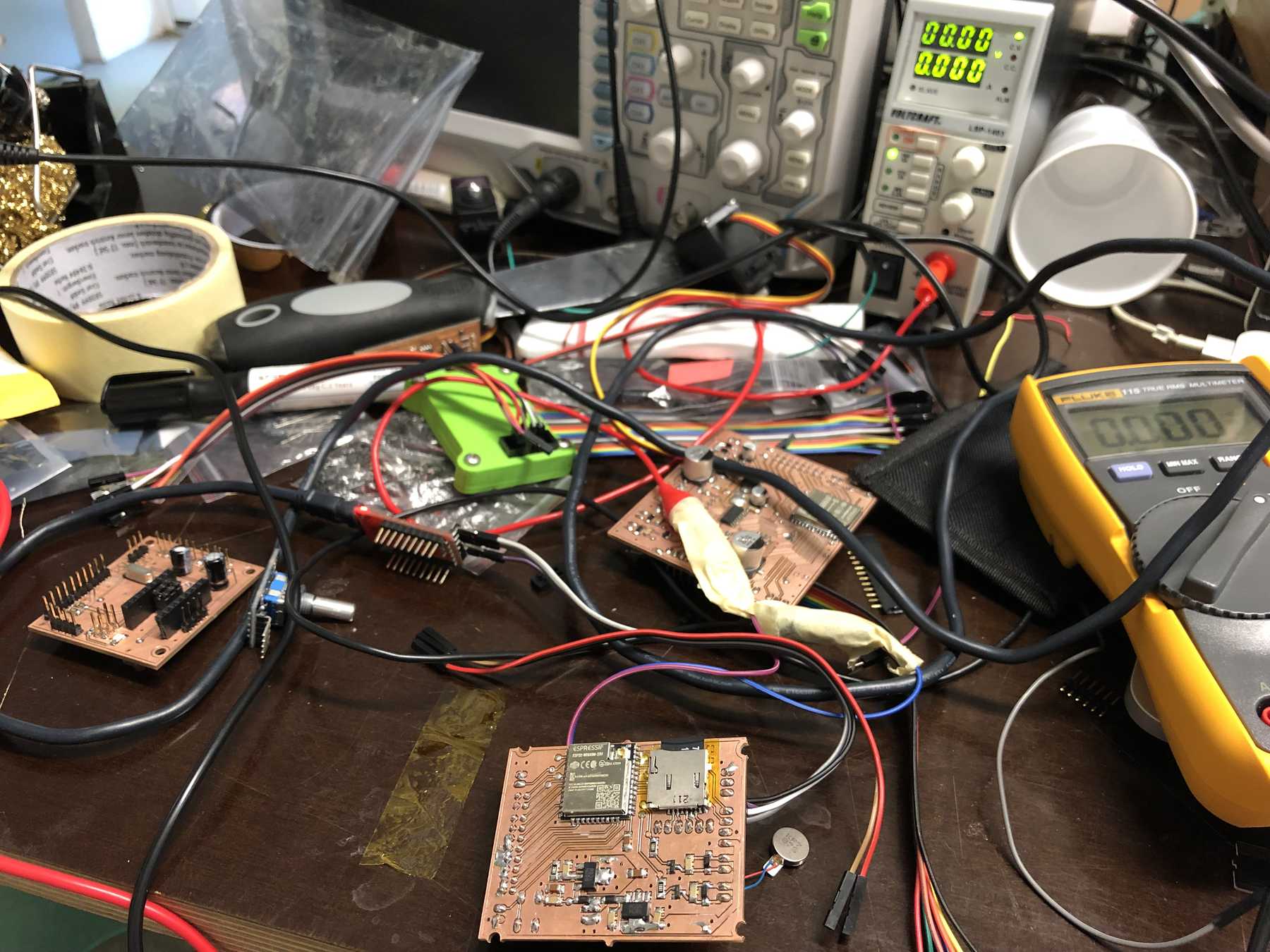
The result was this:
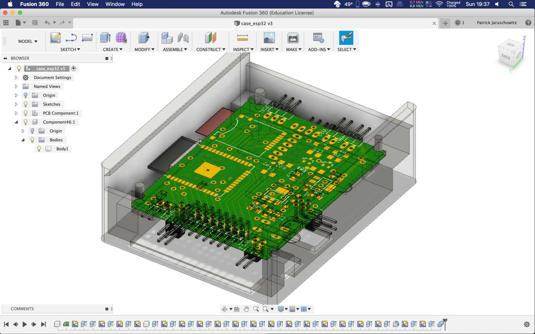
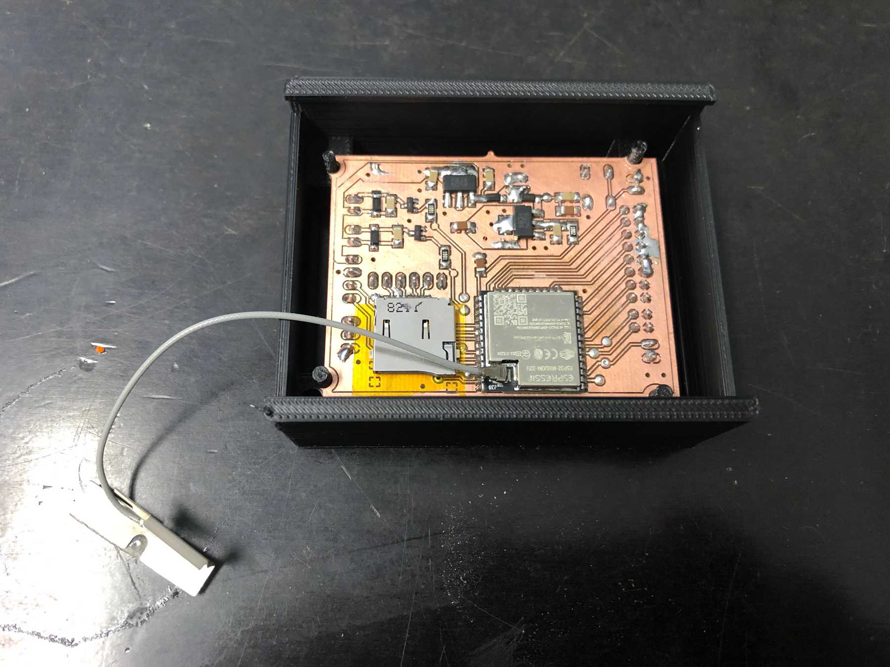
Afterwards a housing was designed for it, which looked as follows:
Pressure mapping
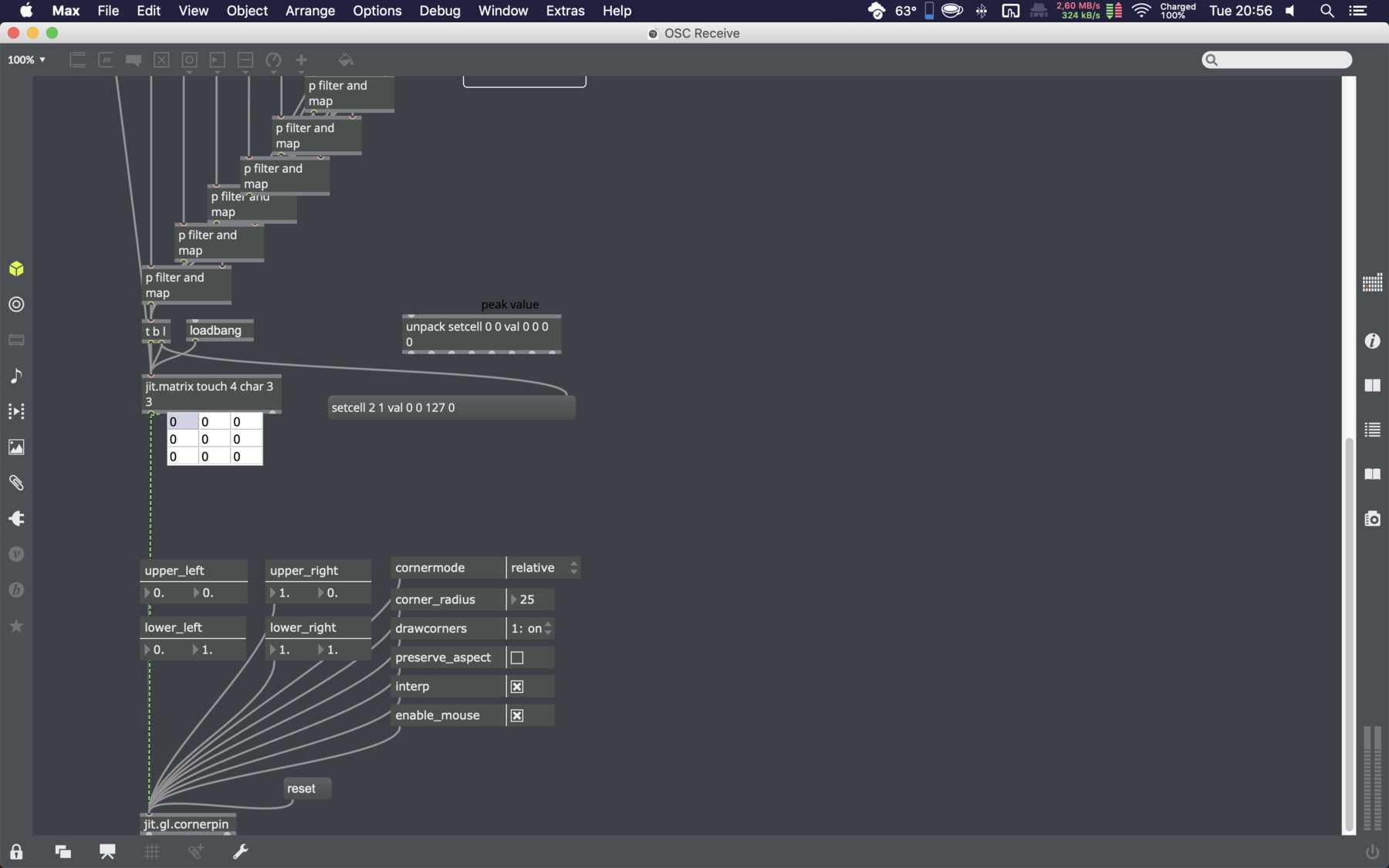
The aim here was to simply process and graphically display the read-out data. Due to the time restrictions, this should be done quickly. Recently I was introduced to Cycling ‘74 Max/MSP. It is a graphical integrated development environment for music and multimedia, which is designed for real-time processes.
The data is transmitted via Open Sound Control (OSC), a message-based network protocol that is mainly used for real-time processing of sound over networks and multimedia installations. Messages are transmitted in OSC in the simplest possible way. An OSC packet consists of its data and a byte indicating the length of the data. It is sent via TCP or UDP. There is also an OSC library for Arduino.
Der Workflow der in Max erarbeitet wurde, sah wie folgt aus:
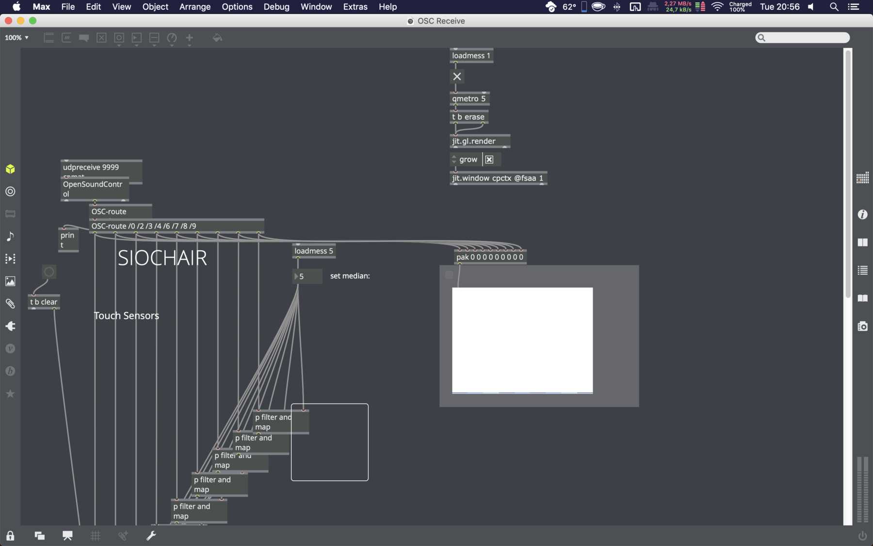
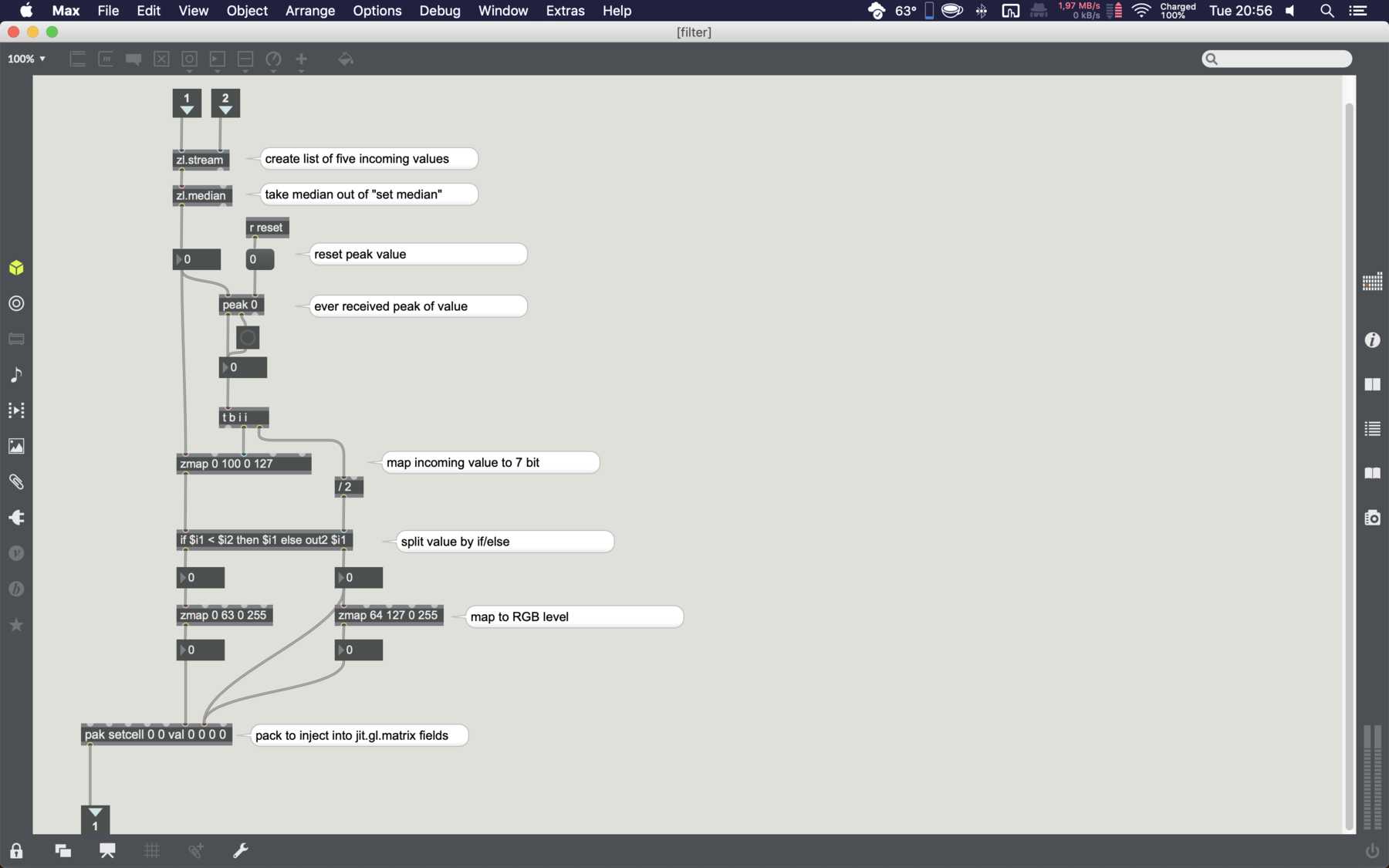
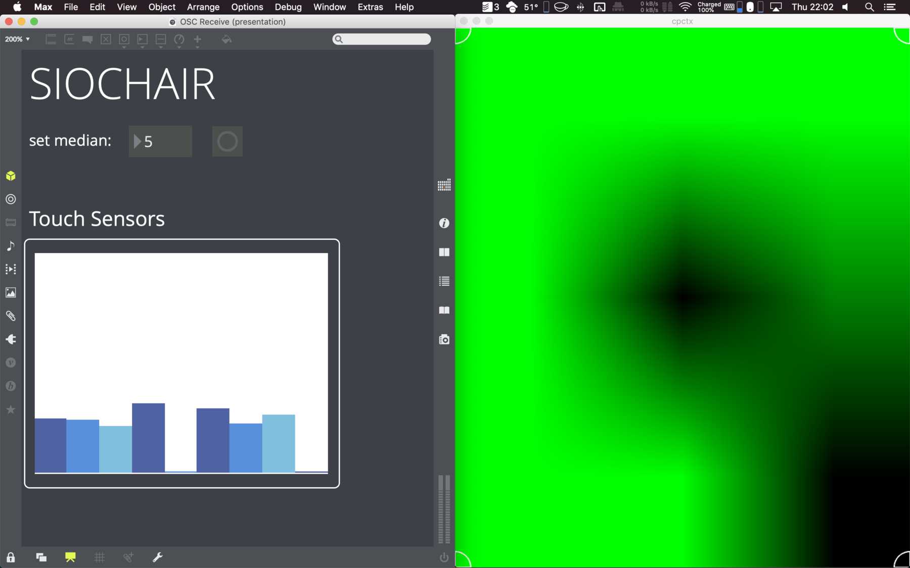
When you switched to presentation mode, only two windows were visible. On the left side the transmitted data, as well as a button for data leveling. Since there are occasionally zero values in the data, I used the median as statistical method. By default it is set to Five. On the right the seat was graphically displayed. Depending on the pressure it changed color.
Pomodoro integration
The Pomodoro technique is a method for time management. The work is divided into 25-minute sections - the so-called pomodori - and break times. I still need two components for the visualization: Display and vibration motor. I have tested these for functionality:
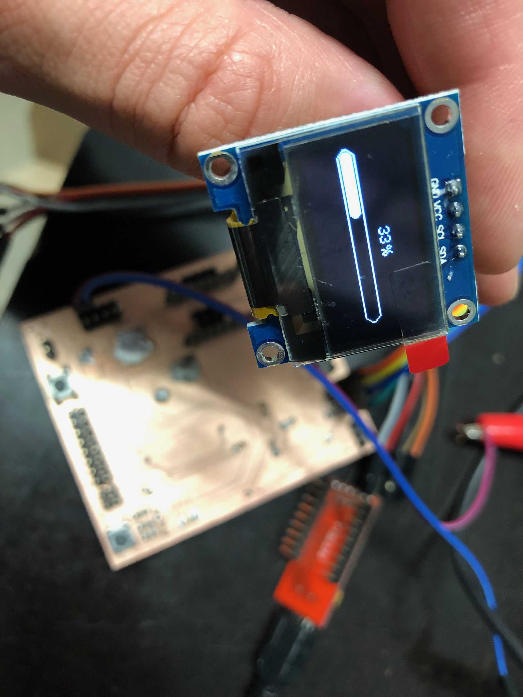
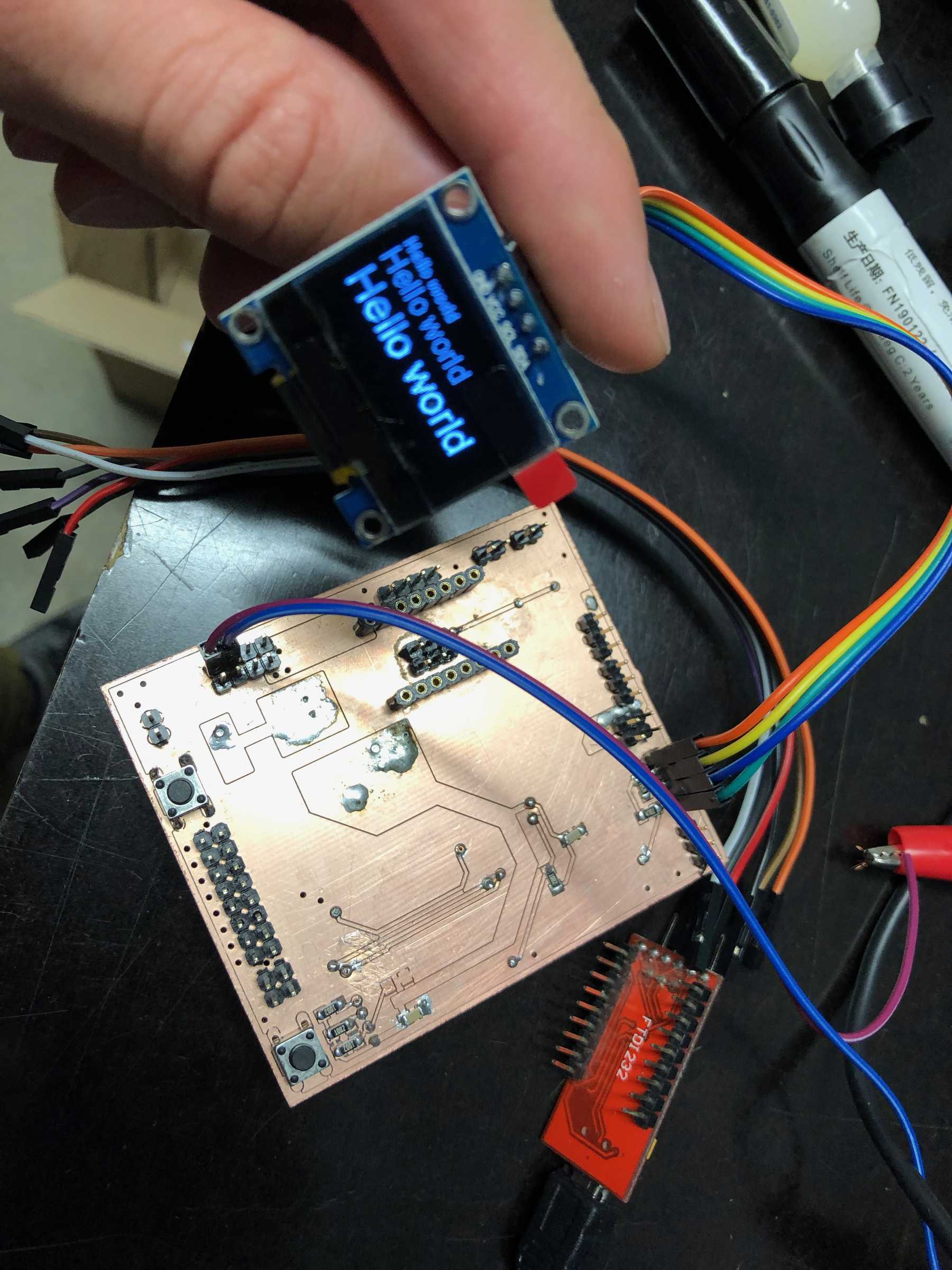

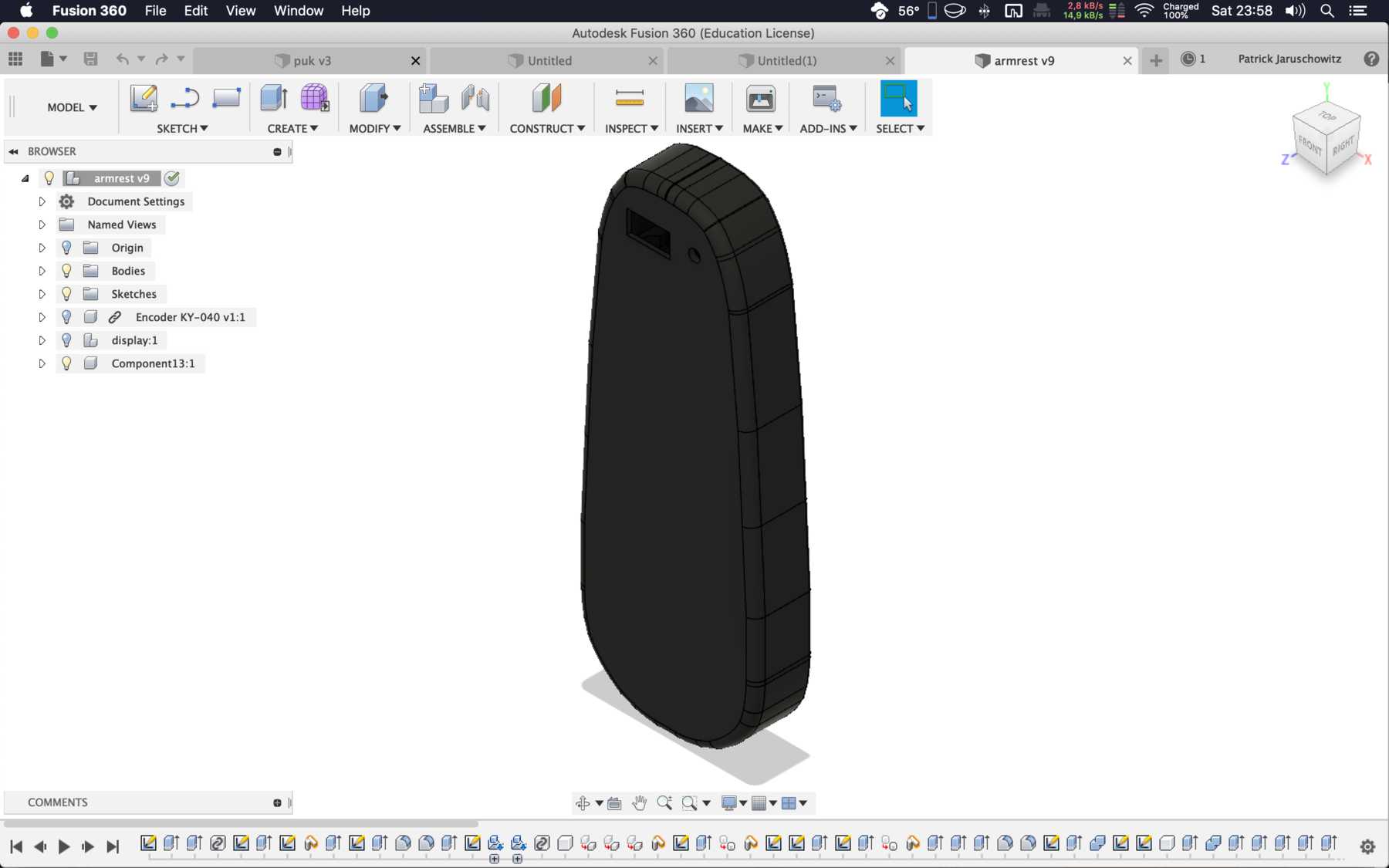
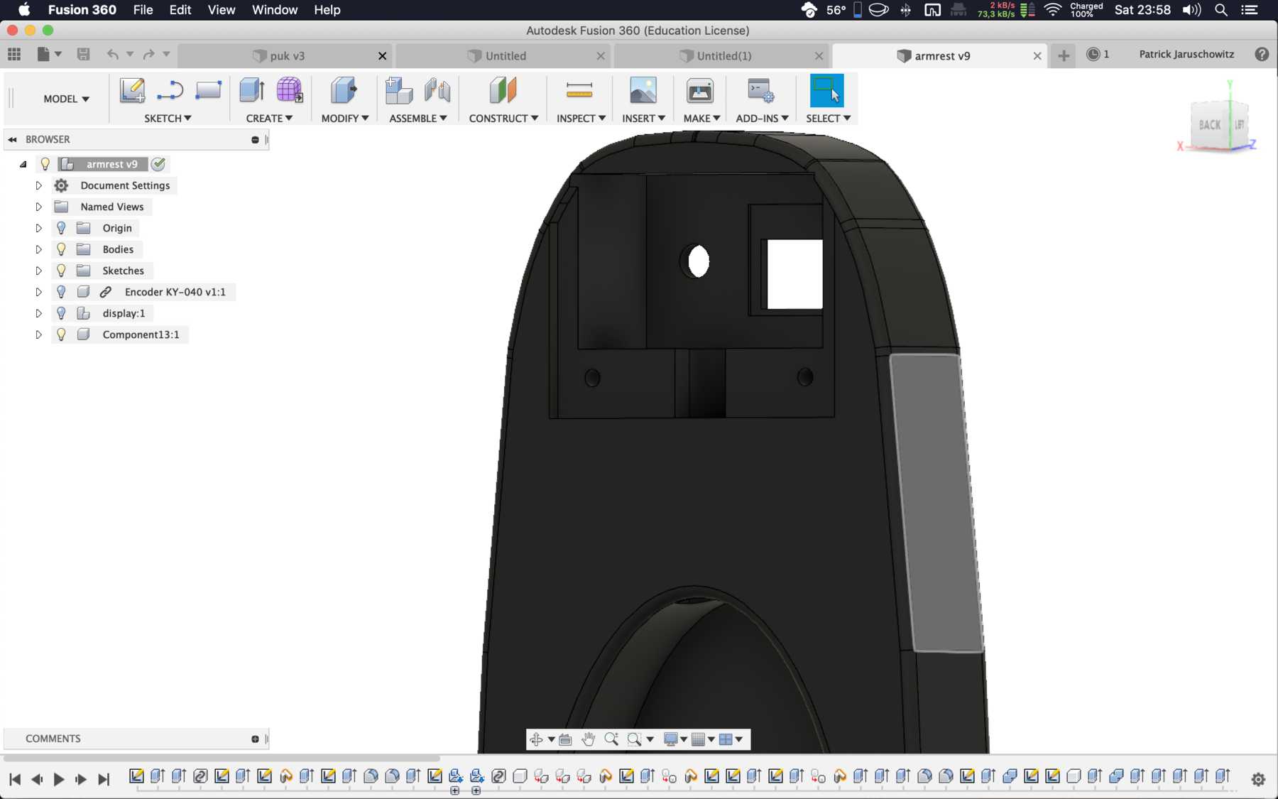
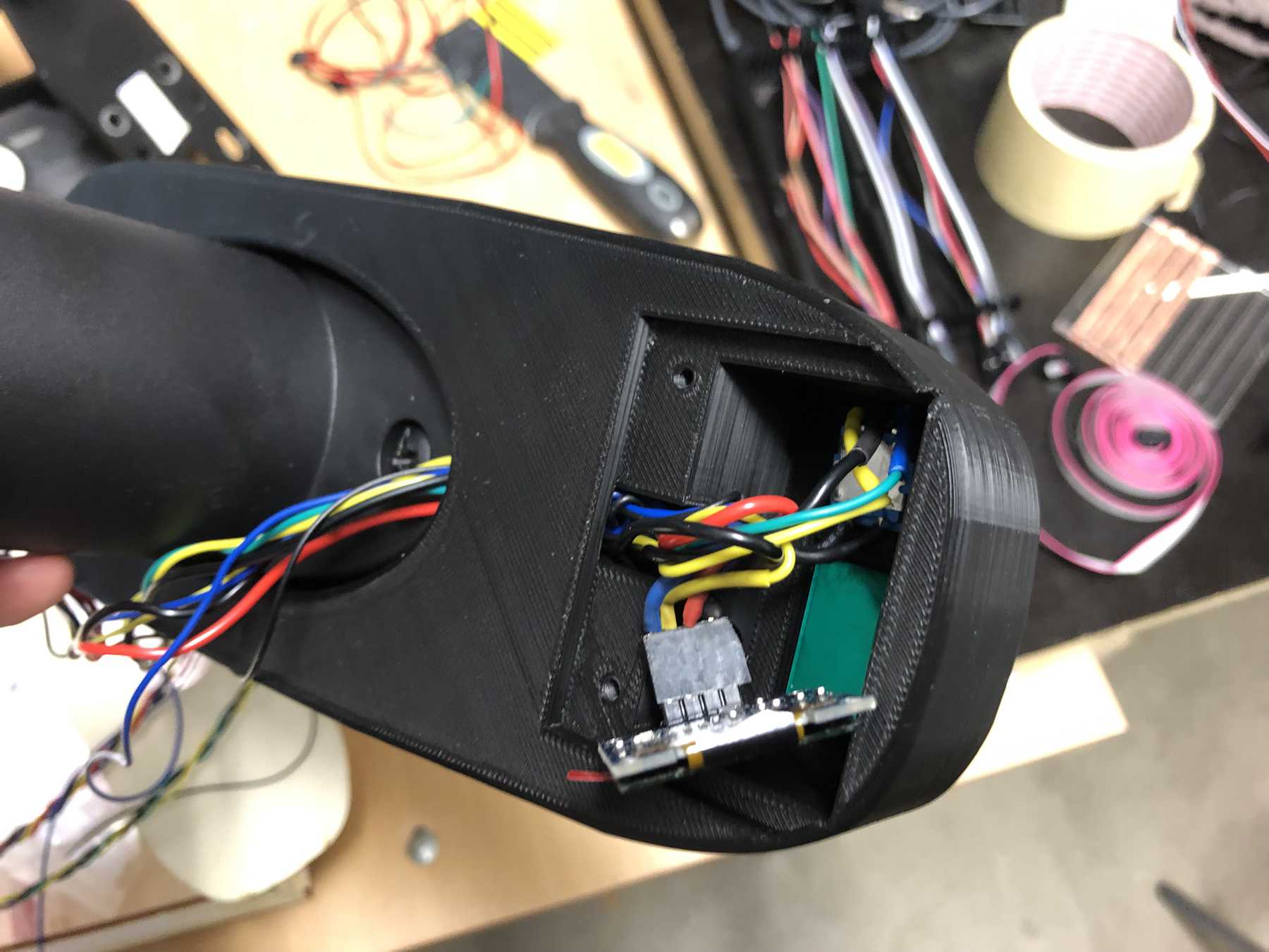
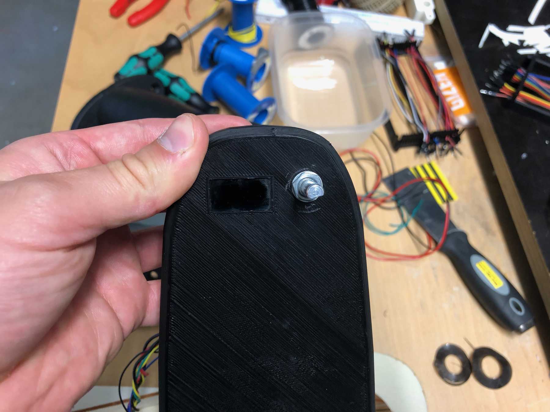
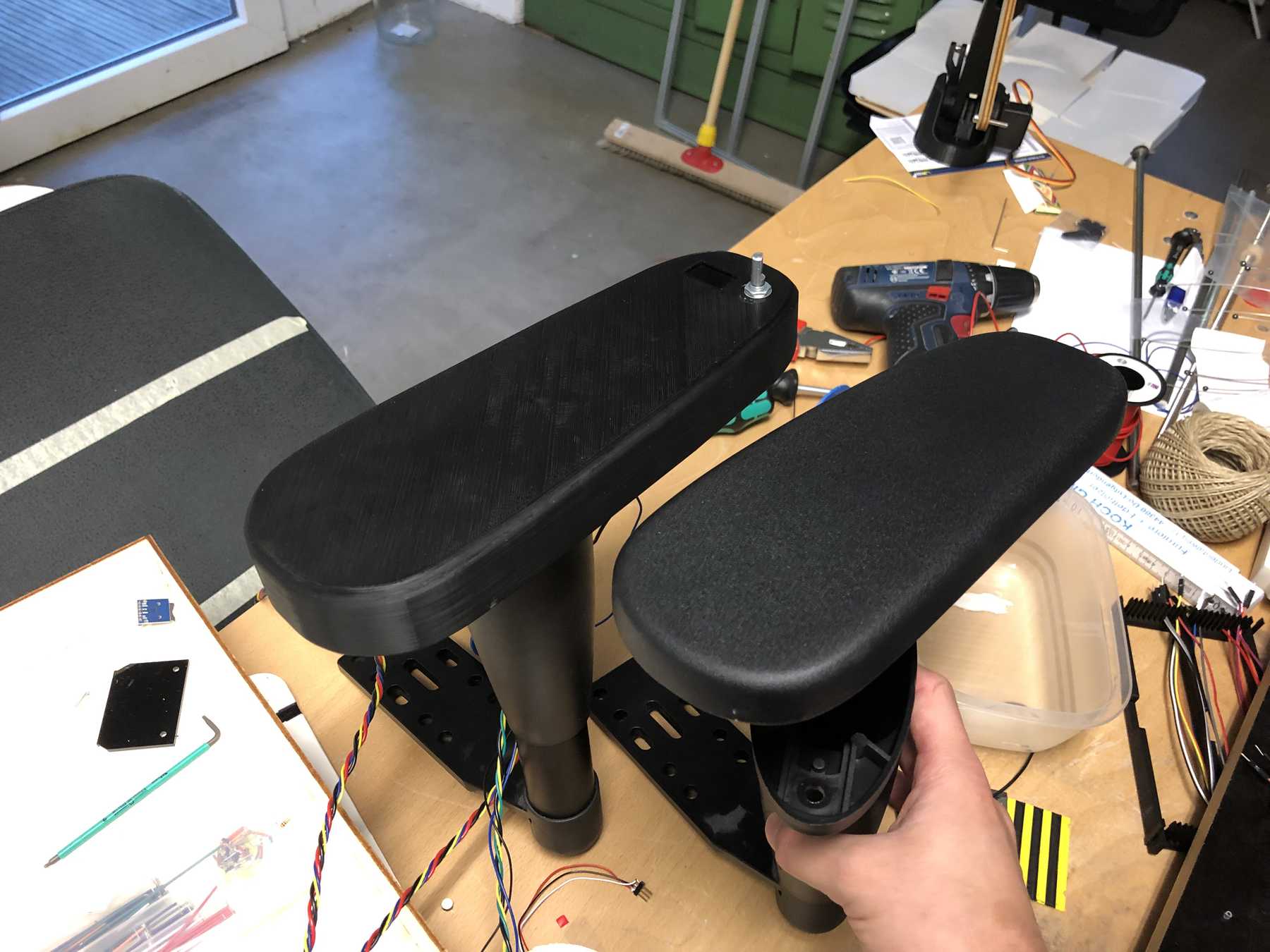
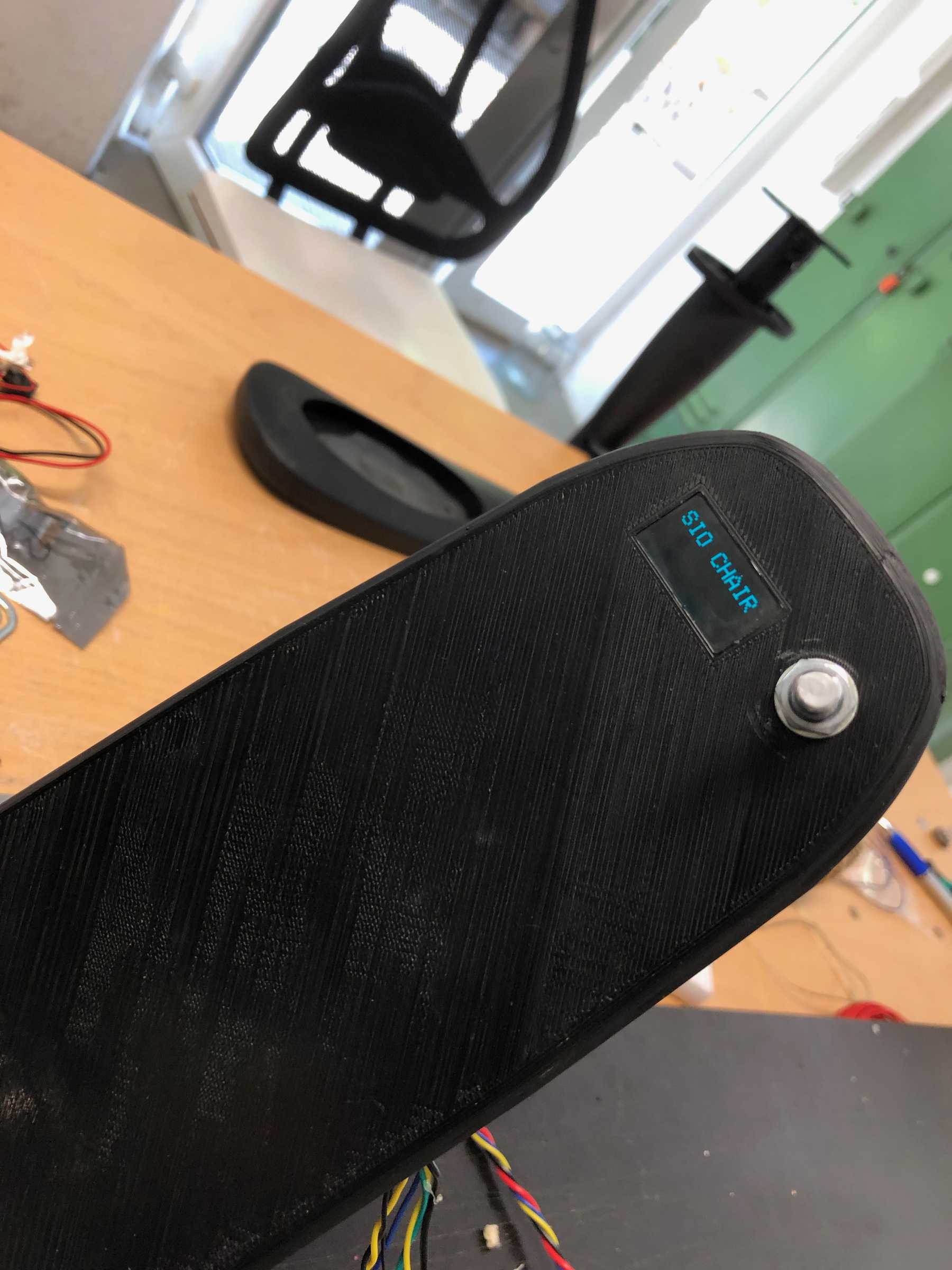
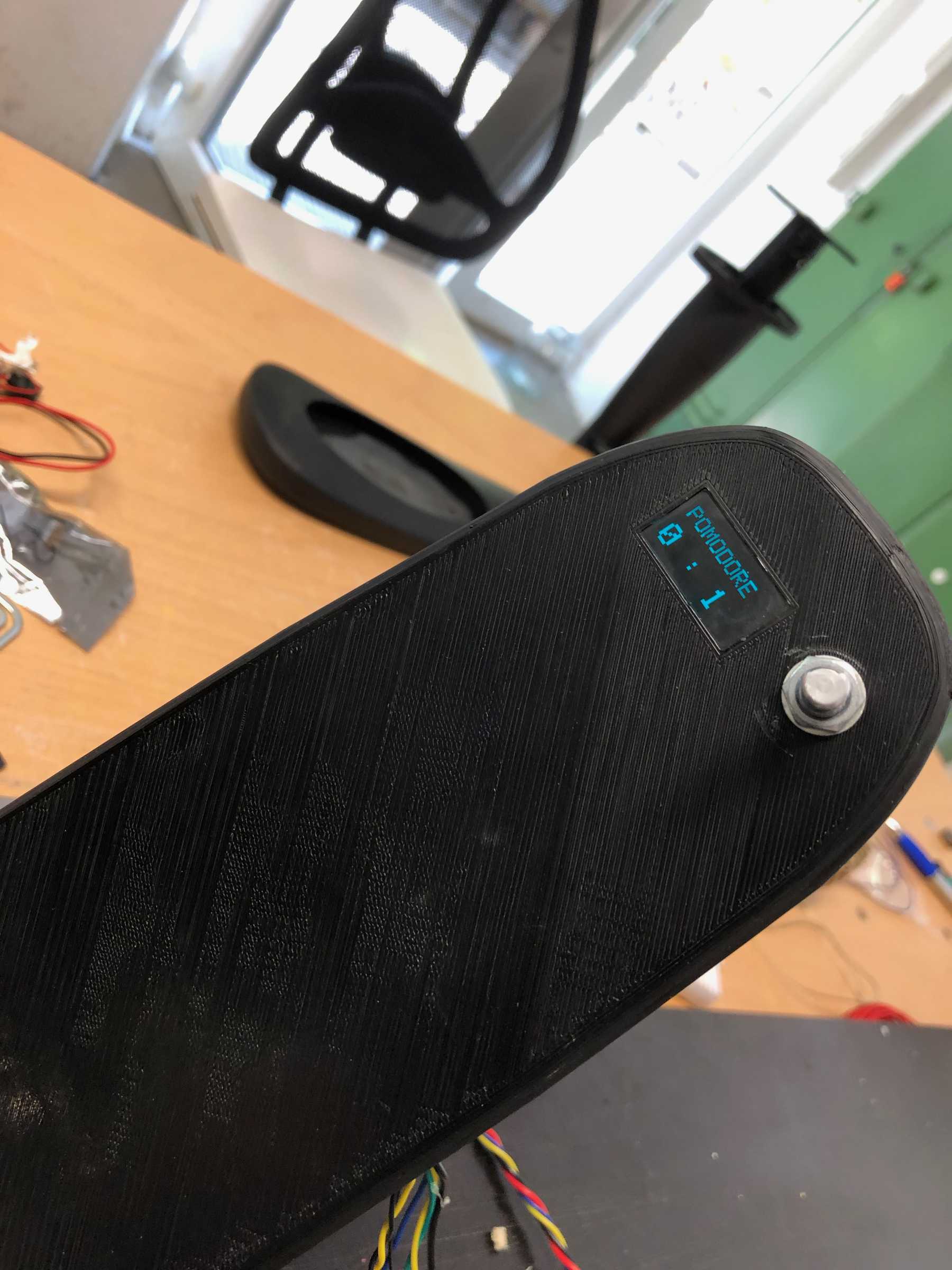
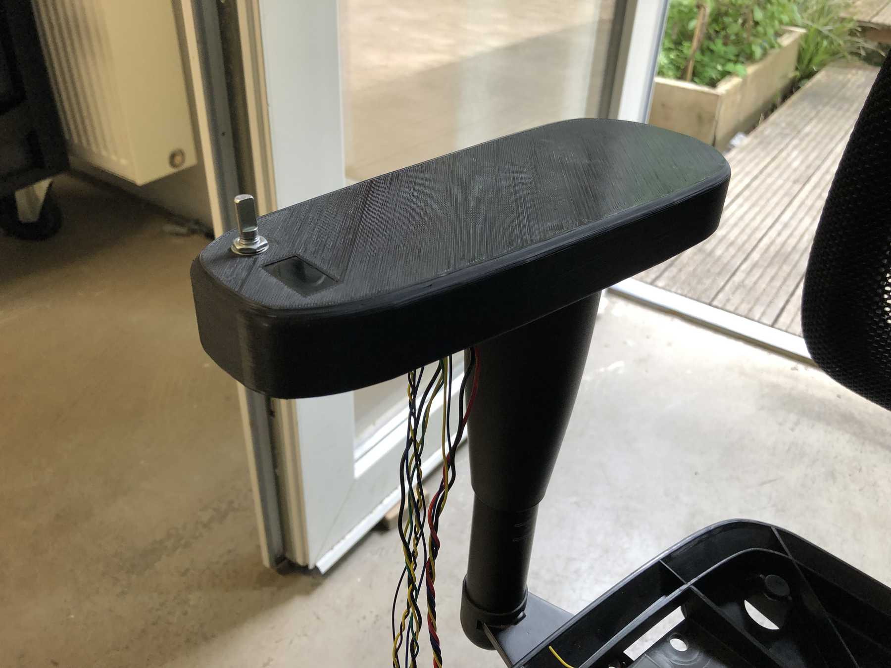
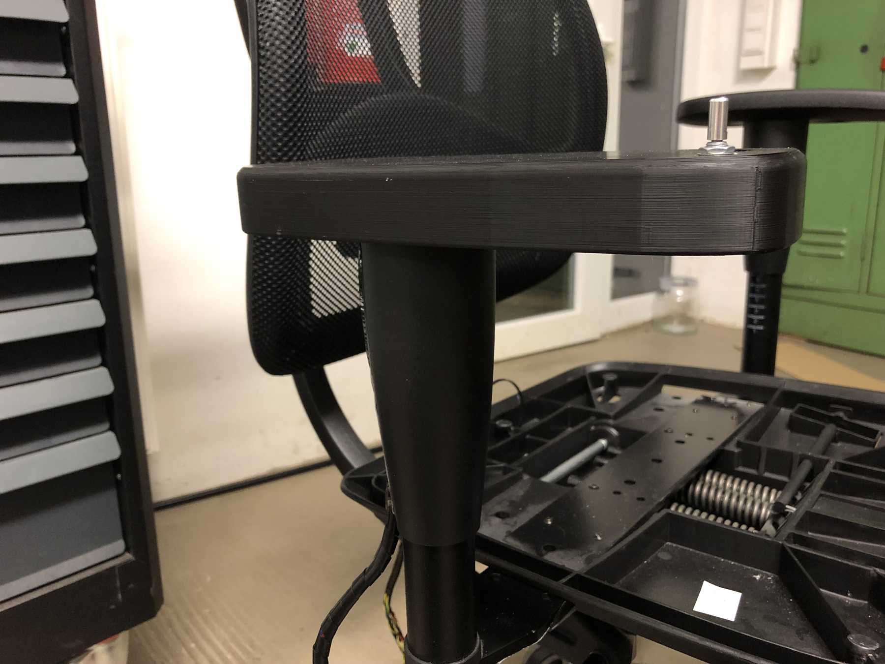
The whole thing should be integrated into the armrest. I drew a 3D model, printed it on the big 3D printer and finished it. In addition to the display and the vibration motor, an encoder with button function was integrated into the armrest.
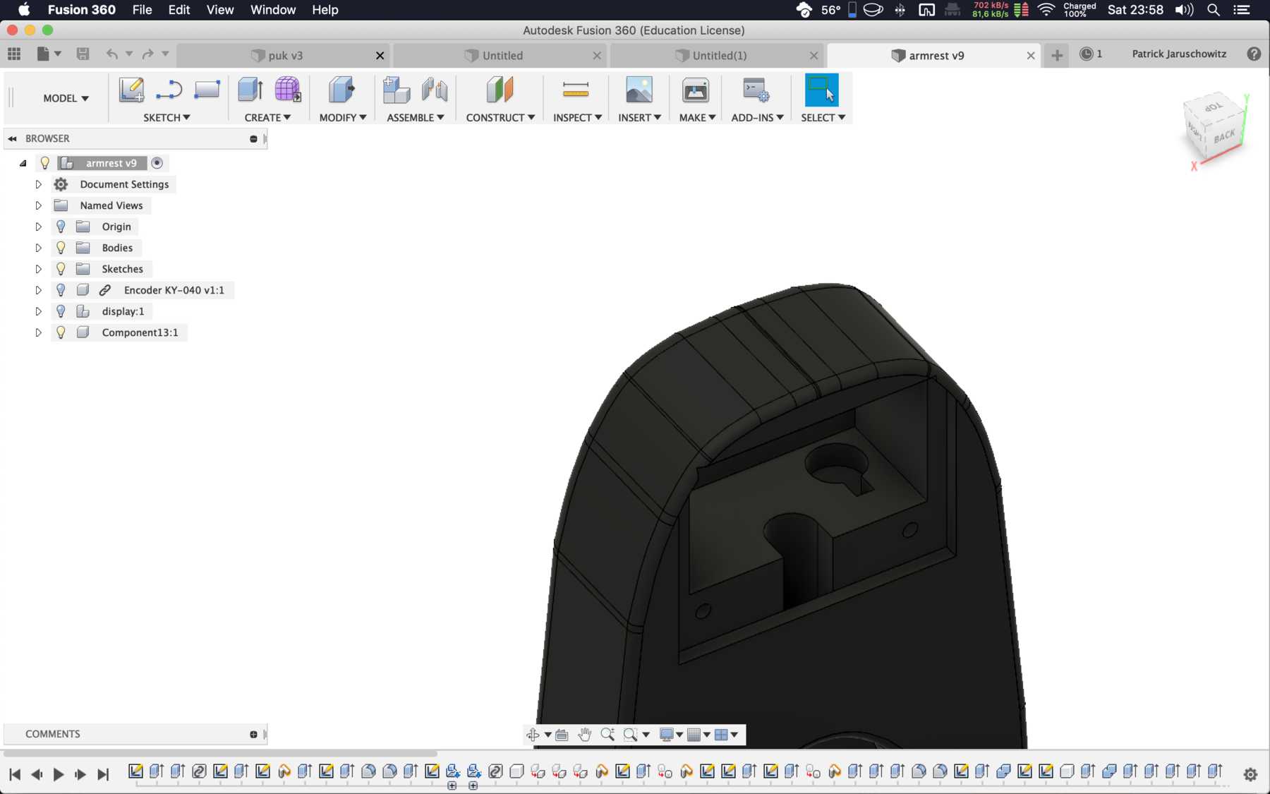
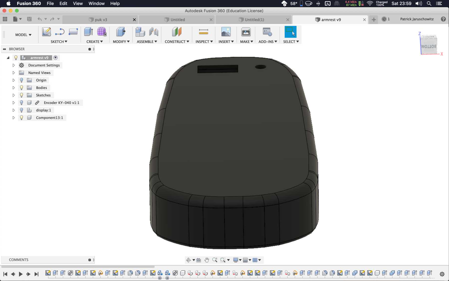
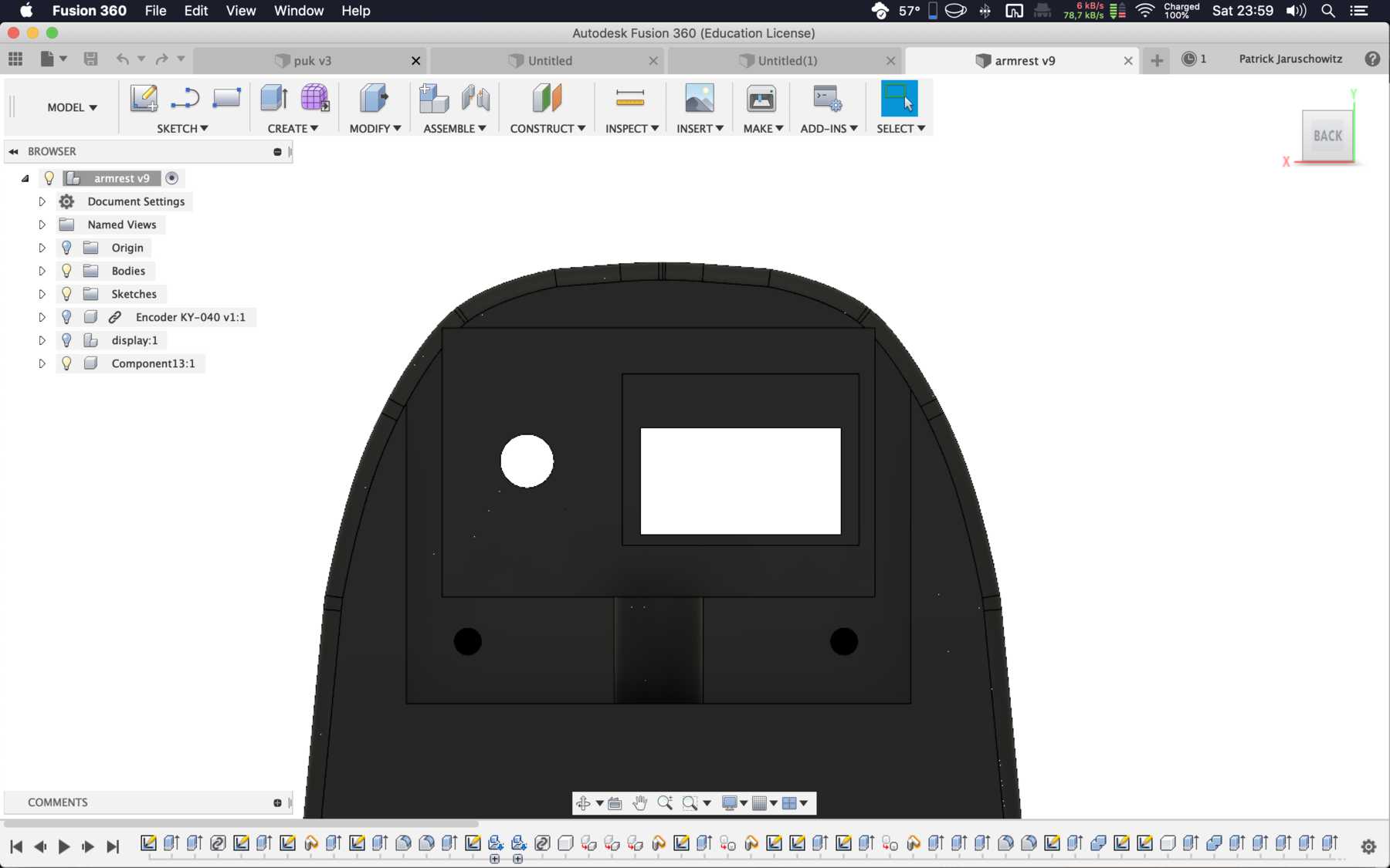
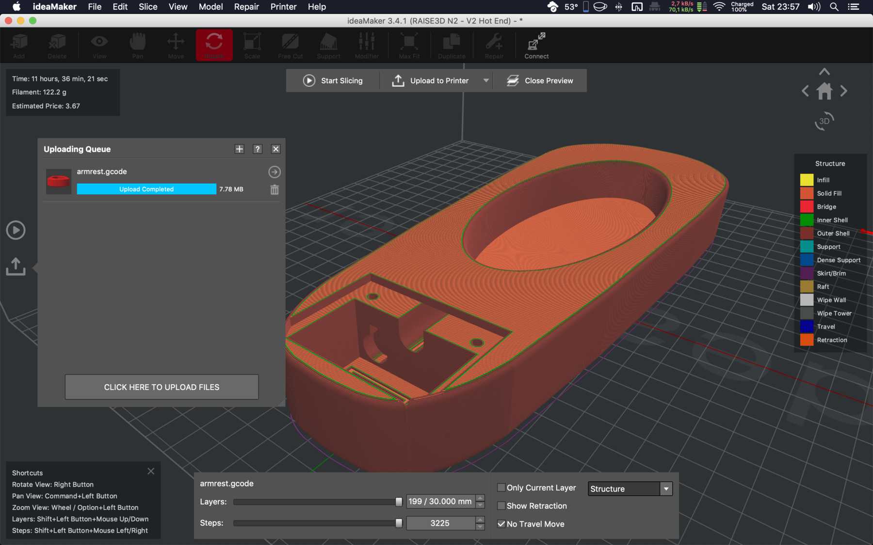
In real life, it looked like this:
Coding
The code is based on Arduino. It uses different libraries for the various components. We have interrupts that activate scenarios. As soon as these are called, different functions are started, such as the Pomodoro function.
Here’s the code for the Arduino sketch:
#include <WiFi.h>
#include <WiFiUdp.h>
#include <OSCMessage.h>
#include <OSCBundle.h>

#include "AiEsp32RotaryEncoder.h"
#include "Arduino.h"
#include "settings.h"

AiEsp32RotaryEncoder rotaryEncoder = AiEsp32RotaryEncoder(ROTARY_ENCODER_A_PIN, ROTARY_ENCODER_B_PIN, ROTARY_ENCODER_BUTTON_PIN, ROTARY_ENCODER_VCC_PIN);
int16_t encoderValue = 0;


//--------------------Includes-------------------------
#include "ArduinoTimer.h" // If missing, install the MegunoLink library:
//"Sketch"-> "Include Library" -> "Manage Libraries..." -> search and install

#include <SPI.h>
#include <Wire.h>
#include <Adafruit_GFX.h>
#include <Adafruit_SSD1306.h>

Adafruit_SSD1306 display(SCREEN_WIDTH, SCREEN_HEIGHT, &Wire, OLED_RESET);


#if (SSD1306_LCDHEIGHT != 64)
#error("Height incorrect, please fix Adafruit_SSD1306.h!");
#endif

//--------------------Class Header-------------------------
// Delay-based simple Button Debounce Class
class DebouncedSwitch
{
    const int m_uDebounceDelayMs = 25; // Increase if bouncing still occurs
    const int m_SwitchPin;
    bool m_bRecentState;
    bool m_bLastSteadyState;
    ArduinoTimer TransitionTimer;

  public:
    DebouncedSwitch(int SwitchPin, bool UseInternalPullup);
    bool Read();
};

//--------------------Class Body-------------------------
DebouncedSwitch::DebouncedSwitch(int SwitchPin, bool UseInternalPullup)
  : m_SwitchPin(SwitchPin)
{
  if (UseInternalPullup)
  {
    pinMode(m_SwitchPin, INPUT);
  }
  else
  {
    pinMode(m_SwitchPin, INPUT);
  }

  m_bRecentState = digitalRead(m_SwitchPin);
  m_bLastSteadyState = m_bRecentState;
}

// Reads pin and returns debounced state
bool DebouncedSwitch::Read()
{
  bool CurrentState = digitalRead(m_SwitchPin);

  if (CurrentState != m_bLastSteadyState) // potential change in steady state
  {
    if (CurrentState != m_bRecentState)
    {
      TransitionTimer.Reset(); // new transition detected, wait for bounces
    }
    else if (TransitionTimer.TimePassed_Milliseconds(m_uDebounceDelayMs, false))
    {
      m_bLastSteadyState = CurrentState; // bouncing should be over by now
    }
  }

  m_bRecentState = CurrentState;

  return m_bLastSteadyState;
}

DebouncedSwitch MyButton(ButtonPin, true);


int test_limits = 4;

void rotary_onButtonClick() {
  //rotaryEncoder.reset();
  //rotaryEncoder.disable();
  rotaryEncoder.setBoundaries(-test_limits, test_limits, false);
  test_limits *= 2;
}

void rotary_loop() {
  //first lets handle rotary encoder button click
  if (rotaryEncoder.currentButtonState() == BUT_RELEASED) {
    //we can process it here or call separate function like:
    rotary_onButtonClick();
  }

  //lets see if anything changed
  int16_t encoderDelta = rotaryEncoder.encoderChanged();

  //optionally we can ignore whenever there is no change
  if (encoderDelta == 0) return;

  //for some cases we only want to know if value is increased or decreased (typically for menu items)
  if (encoderDelta > 0) Serial.print("+");
  if (encoderDelta < 0) Serial.print("-");

  //for other cases we want to know what is current value. Additionally often we only want if something changed
  //example: when using rotary encoder to set termostat temperature, or sound volume etc

  //if value is changed compared to our last read
  if (encoderDelta != 0) {
    refreshDisplay = true;
    //now we need current value
    encoderValue = rotaryEncoder.readEncoder();
    //process new value. Here is simple output.
    Serial.print("Value: ");
    Serial.println(encoderValue);
  }

}

//--------------------Setup-------------------------
void setup()
{
  // Setup serial for outputting button press count
  Serial.begin(115200);
  Serial.println("SIOCHAIR");

  // SSD1306
  display.begin(SSD1306_SWITCHCAPVCC, 0x3C);  // initialize with the I2C addr 0x3D (for the 128x64)
  // internally, this will display the splashscreen.
  display.display();
  display.invertDisplay(false);
  display.setRotation(2);
  //delay(2000);
  display.clearDisplay();


  // OSC
  Serial.print("Connecting to ");
  Serial.println(ssid);
  WiFi.begin(ssid, pass);

  while (WiFi.status() != WL_CONNECTED) {
    delay(500);
    Serial.print(".");
  }
  Serial.println("");

  Serial.println("WiFi connected");
  Serial.println("IP address: ");
  Serial.println(WiFi.localIP());

  Serial.println("Starting UDP");
  Udp.begin(localPort);
  Serial.print("Local port: ");
  Serial.println(localPort);

  // BUTTON
  // Setup last state variable used to detect button changes
  LastState = MyButton.Read();

  // VIB MOTOR
  // Setup onboard LED pin for indicating button state
  pinMode(LedPin, OUTPUT);


  // ENCODER
  //we must initialize rorary encoder
  rotaryEncoder.begin();
  rotaryEncoder.setup([] {rotaryEncoder.readEncoder_ISR();});
  //optionally we can set boundaries and if values should cycle or not
  rotaryEncoder.setBoundaries(0, 1, true); //minValue, maxValue, cycle values (when max go to min and vice versa)
}


//--------------------Loop-------------------------
void loop()
{
  rotary_loop();
  if (millis() > encoderWait) rotaryEncoder.enable ();

  // Read the debounced button state:
  // using        MyButton.Read()
  // instead of   digitalRead(ButtonPin)

  bool CurrentState = MyButton.Read();

  // Turn on LED if the button is being pressed
  if (CurrentState == LOW) // level-sensitive
  {
    digitalWrite(LedPin, HIGH);
    pomoAction = true;

  } else {
    digitalWrite(LedPin, LOW);
  }

  // Increment and print the count at the start of each button press
  if (CurrentState == LOW && CurrentState != LastState) // edge-sensitive
  {
    //pomoAction = true;
    //refreshDisplay = true;

    Count++;
    Serial.print("Count: ");
    Serial.println(Count);

  }

  // Store button state so changes can be detected
  LastState = CurrentState;

  if (pomoCount >= pomoCountMax) {
    Serial.println("reached max. reset pomoCount");
    pomoAction = false;
    pomoReset = true;
    display.clearDisplay();
    display.setTextSize(2);
    display.setTextColor(WHITE);
    display.setCursor(10, 5);
    display.println("take a break");  // Clear the buffer.
    display.display();
    digitalWrite(LedPin, HIGH);
    delay(200);
    digitalWrite(LedPin, LOW);
    delay(500);
    digitalWrite(LedPin, HIGH);
    delay(200);
    digitalWrite(LedPin, LOW);
    delay(500);
    refreshDisplay = true;
    encoderValue = 2;


  }


  if (encoderValue == 1) {
    //pomoAction = true;
    //pomoCount = 0;
    //Serial.println("count2");
  }
  else if (encoderValue != 2) {
    selectAction == 3;
    pomoAction = false;
    pomoReset = true;
  }
  if (Count >= maxCount) {
    Count = 0;
  }
  //pomoCurrentTime = millis();
  if (pomoReset == true) {
    pomoReset = false;
    pomoCount = 0;
  }


  if ((millis() - pomoCurrentTime) > 1000 && pomoAction == true && encoderValue == 1) {
    //Serial.println(pomoCurrentTime);

    if (pomoCount < pomoCountMax) {
      pomoCount ++;
      Serial.printf("pomoCount: %d \n", pomoCount);
      refreshDisplay = true;
    }

    pomoCurrentTime = millis();
  }
  if (refreshDisplay == true) {
    uint32_t seconds = pomoCount;
    display.clearDisplay();
    display.setTextSize(2);
    display.setTextColor(WHITE);
    display.setCursor(10, 5);

    if (encoderValue != 1) {
      display.println("SIOCHAIR");  // Clear the buffer.
      refreshDisplay = false;
    }
    else if (encoderValue == 1) {
      uint32_t s = seconds % 60;
      seconds = (seconds - s) / 60;
      uint32_t m = seconds % 60;

      display.println("POMODORE");  // Clear the buffer.
      display.setTextSize(3);
      display.setTextColor(WHITE);
      display.setCursor(10, 30);
      display.println(String(m) + ":" + String(s));  // Clear the buffer.
      //display.setTextSize(2);
      //display.println("secs");  // Clear the buffer.

      refreshDisplay = false;

    }
    else {
      display.println(encoderValue);  // Clear the buffer.
      refreshDisplay = false;

    }
    display.display();
    delay(100);
  }
  if ((millis() - oscSendTime) > oscInterval) {
    uint8_t t0 = touchRead(T0);
    uint8_t t2 = touchRead(T2);
    uint8_t t3 = touchRead(T3);
    uint8_t t4 = touchRead(T4);
    uint8_t t6 = touchRead(T6);
    uint8_t t7 = touchRead(T7);
    uint8_t t8 = touchRead(T8);
    uint8_t t9 = touchRead(T9);
    //declare the bundle
    OSCBundle bndl;
    //BOSCBundle's add' returns the OSCMessage so the message's 'add' can be composed together
    bndl.add("/touch/0").add((int32_t)t0);
    bndl.add("/touch/2").add((int32_t)t2);
    bndl.add("/touch/3").add((int32_t)t3);
    bndl.add("/touch/4").add((int32_t)t4);
    bndl.add("/touch/6").add((int32_t)t6);
    bndl.add("/touch/7").add((int32_t)t7);
    bndl.add("/touch/8").add((int32_t)t8);
    bndl.add("/touch/9").add((int32_t)t9);

    Udp.beginPacket(outIp, outPort);
    bndl.send(Udp);
    Udp.endPacket();
    bndl.empty();

    oscSendTime = millis();
  }
}
Here is the code for the settings.h:
#define ROTARY_ENCODER_A_PIN 34
#define ROTARY_ENCODER_B_PIN 35
#define ROTARY_ENCODER_BUTTON_PIN 0
#define ROTARY_ENCODER_VCC_PIN -1 /*put -1 of Rotary encoder Vcc is connected directly to 3,3V; else you can use declared output pin for powering rotary encoder */
#define encoderWait 20000

#define pomoCountMax

//#define pomoCountMax 1500
uint32_t pomoCurrentTime = 0;
uint32_t pomoCurrentTimeOld = 0;
#define maxCount 2
bool refreshDisplay = true;

int selectAction = 0;
bool pomoAction = false;
uint16_t pomoCount = 0;
bool pomoReset = true;

#define SCREEN_WIDTH 128 // OLED display width, in pixels
#define SCREEN_HEIGHT 64 // OLED display height, in pixels
#define OLED_RESET -1
#define LED_BUILTIN 16
const int ButtonPin = 0;  // Pin number of the user's button
const int LedPin = 26;    // Pin number of the onboard LED
bool LastState;           // Previous button state seen in loop()
unsigned int Count = 0;   // Count of button presses seen in loop()


char ssid[] = "DEZENTRALE";          // your network SSID (name)
char pass[] = "";                    // your network password

WiFiUDP Udp;                                // A UDP instance to let us send and receive packets over UDP
const IPAddress outIp(192, 168, 1, 169);     // remote IP of your computer
const unsigned int outPort = 9999;          // remote port to receive OSC
const unsigned int localPort = 8888;        // local port to listen for OSC packets (actually not used for sending)

#define oscInterval 100
uint32_t oscSendTime;
uint32_t oscSendTimeOld = 0;
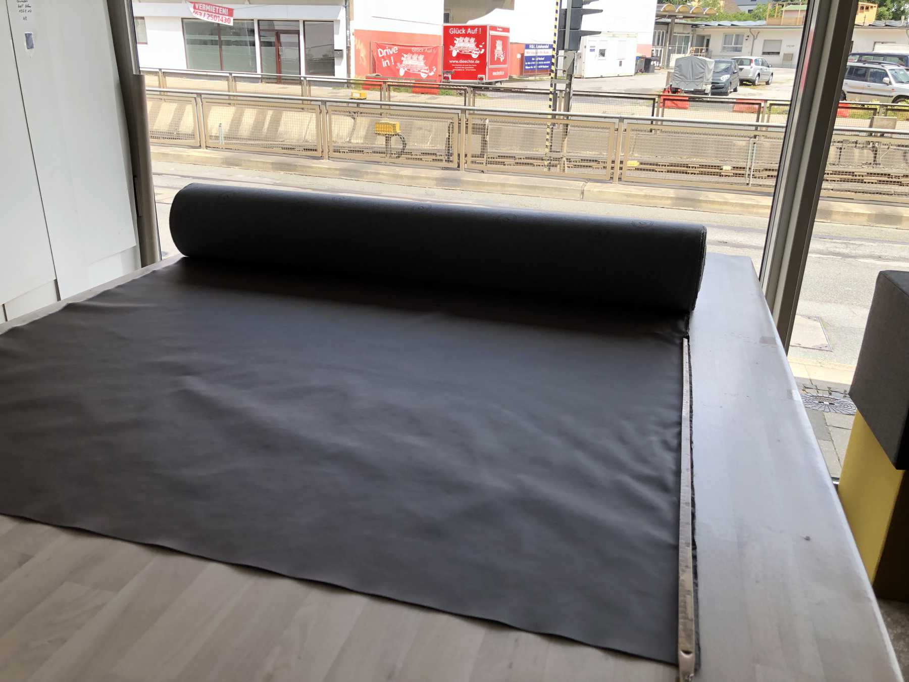
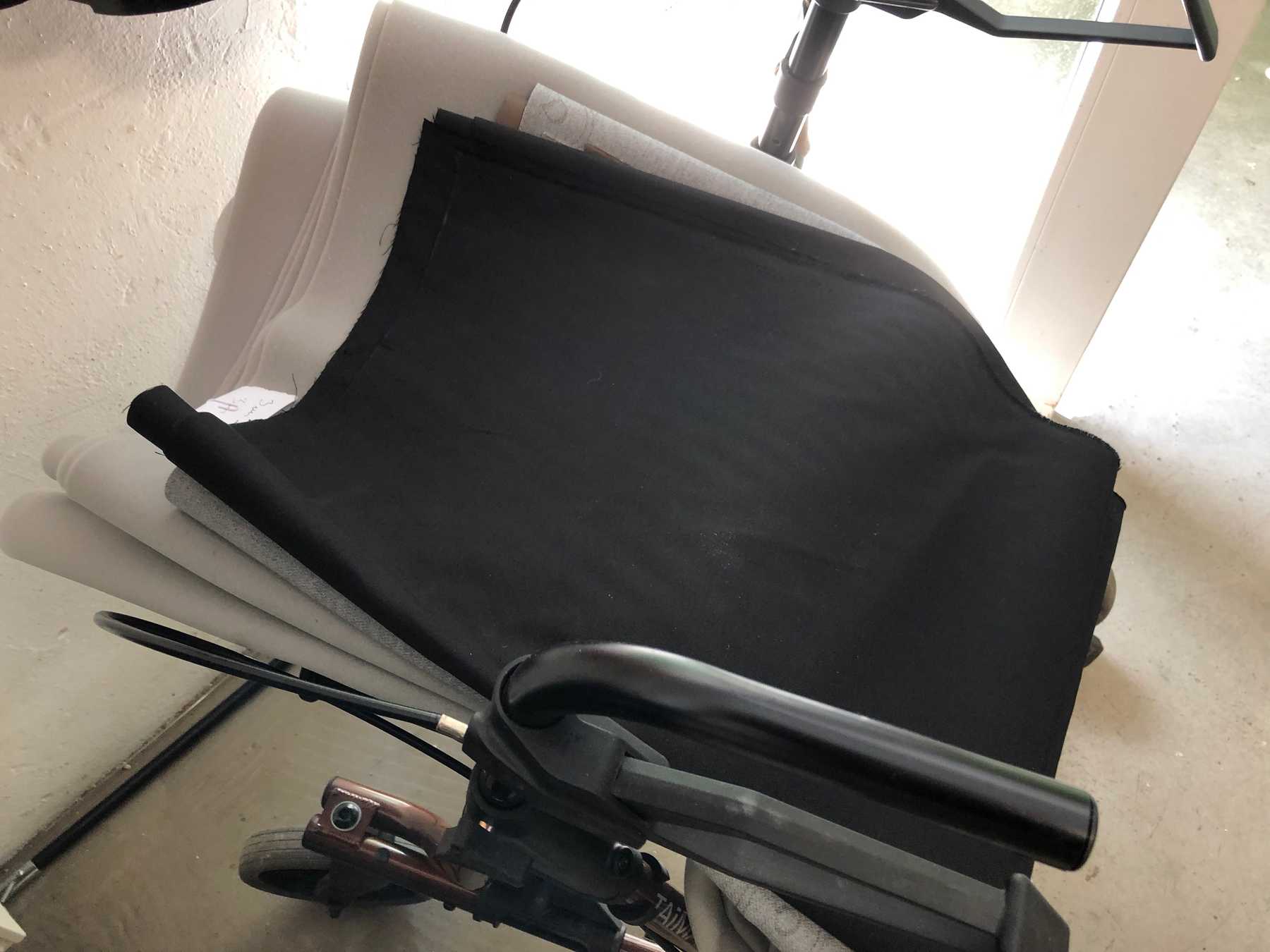
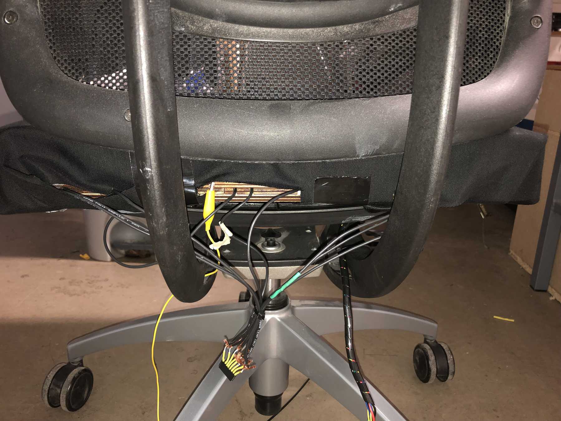
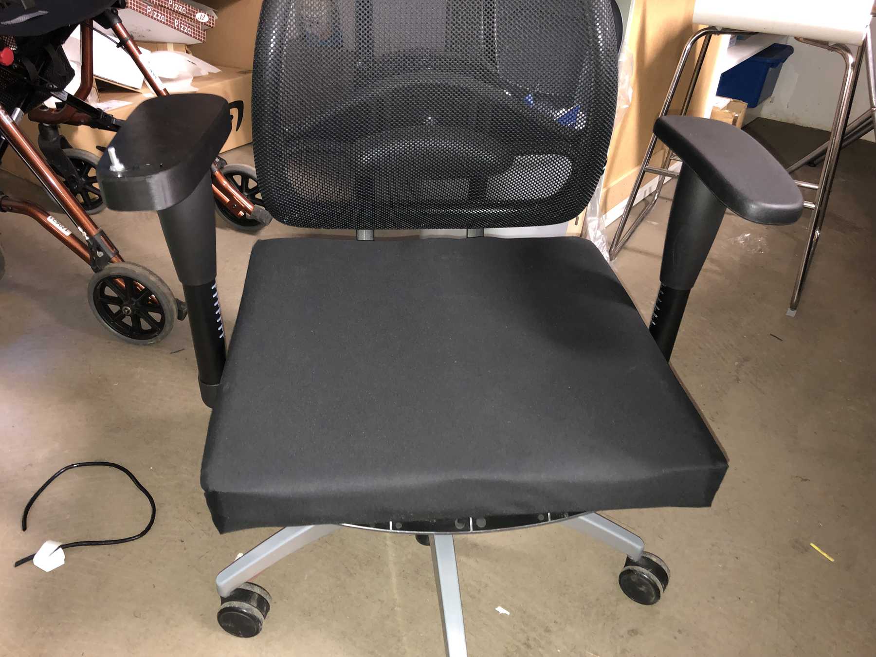
Assembling the chair
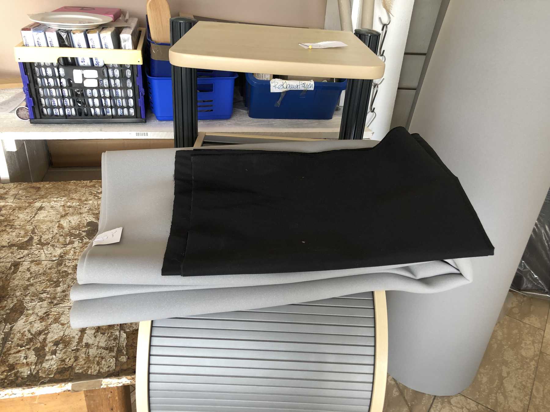
At the end the chair had to be assembled. For this I bought fabric and 3mm foam. The following pictures should show how all this was assembled until the end.


Here you can download all the files:
3D-model as Cura files (smaller as STEP or STL)
Armrest files
Pressure elements files
Max sketch
Arduino files
Take a look at the presentation