Input Devices
Week 11
In this week the individual task was to measure something, no matter what, mainly the microcontroller board was designed by myself and could measure something. The group assignment was: probe an input device’s analog levels and digital signals.
Group assignment
Digital signal from an input device
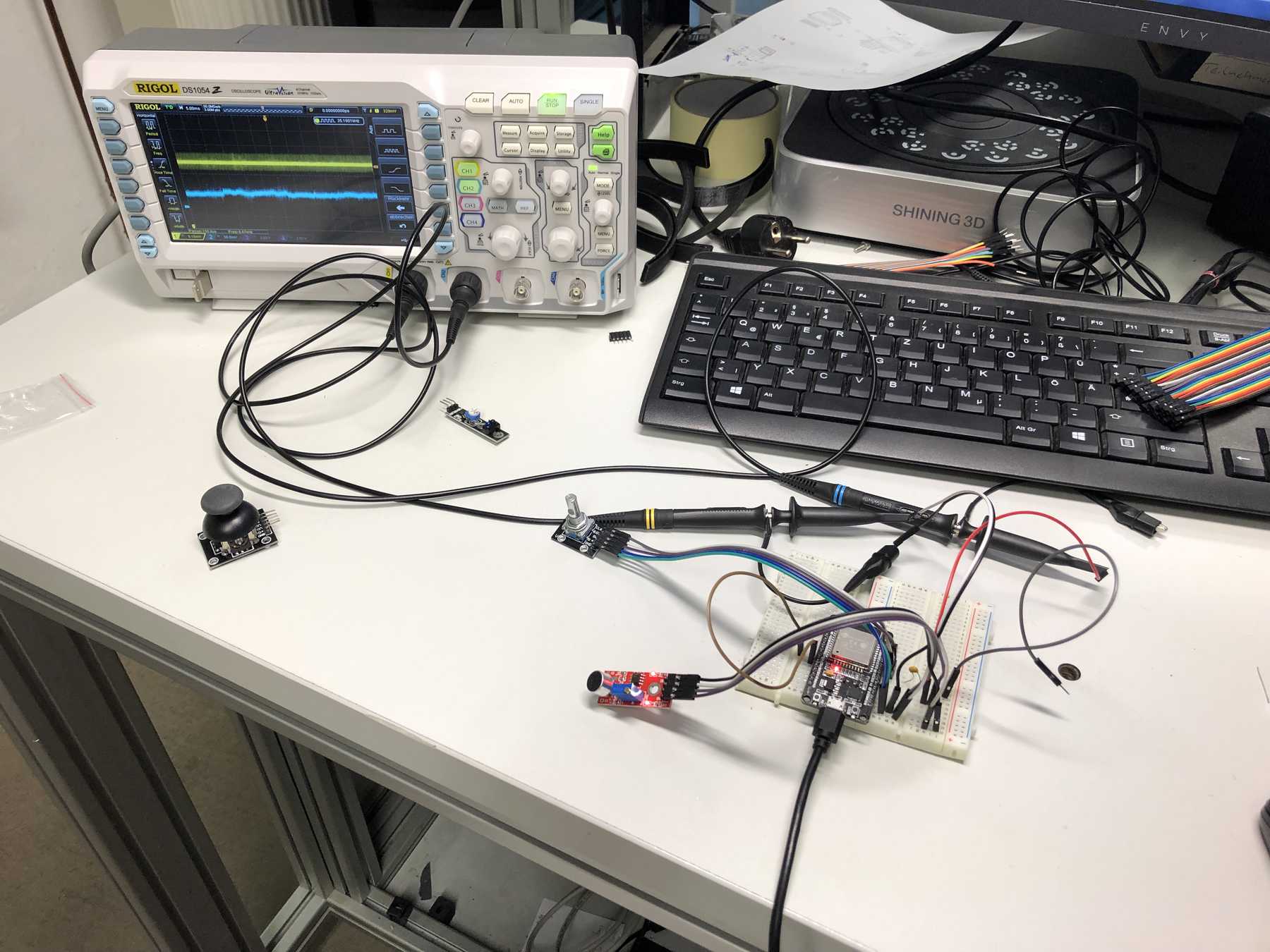
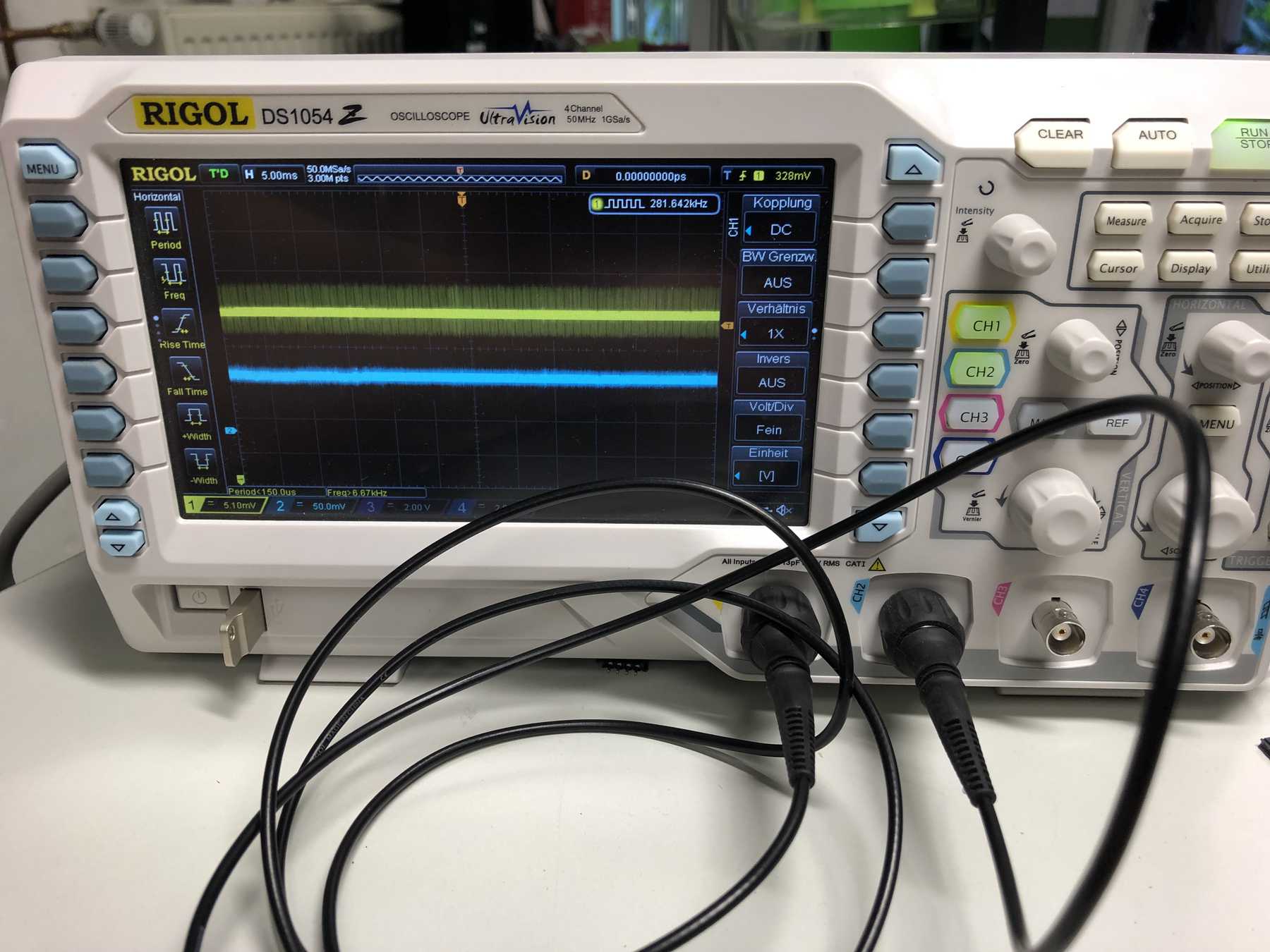
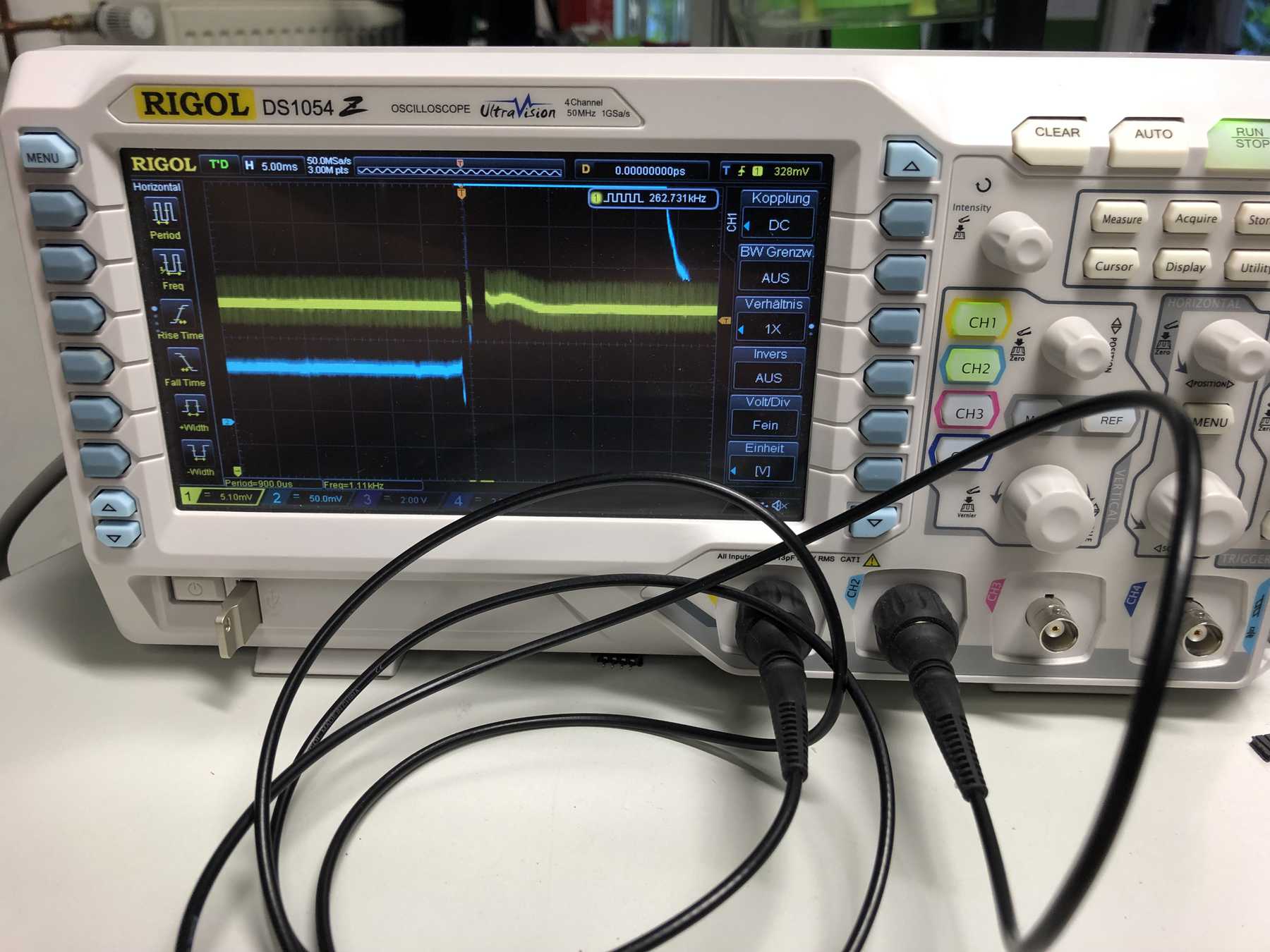
In the group assignment we should measure an input device with regard to analog levels and digital signals. For the first experiment I used a microphone as input device and then measured the analog out and the digital out of the input device over an oscilloscope. The trimmer can be used to measure the trigger voltage or trigger voltage at which it triggers, i.e. digitally switches from low to high. On the pictures you can see two states: One where I scream and one where it is quiet. Yellow is analog, blue is digital. It is a microphone that converts the sound energy into a variable voltage. The variable voltage is output directly via the analog A0 and can be picked up (from the oscilloscope). The analog voltage is not decoupled AC.
Then there was another example with a joystick. Here the analog signal was displayed using the Arduino serial plotter. Depending on the displacement of the joystick you can see the voltage variation.
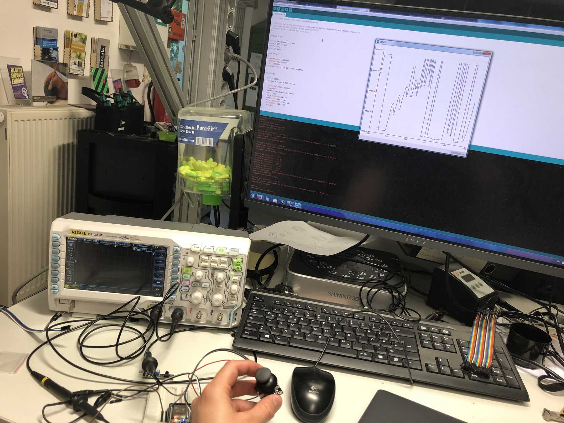
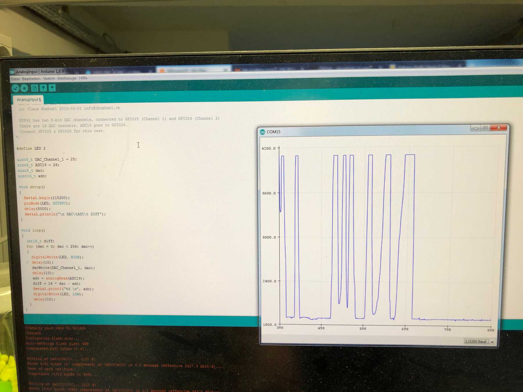
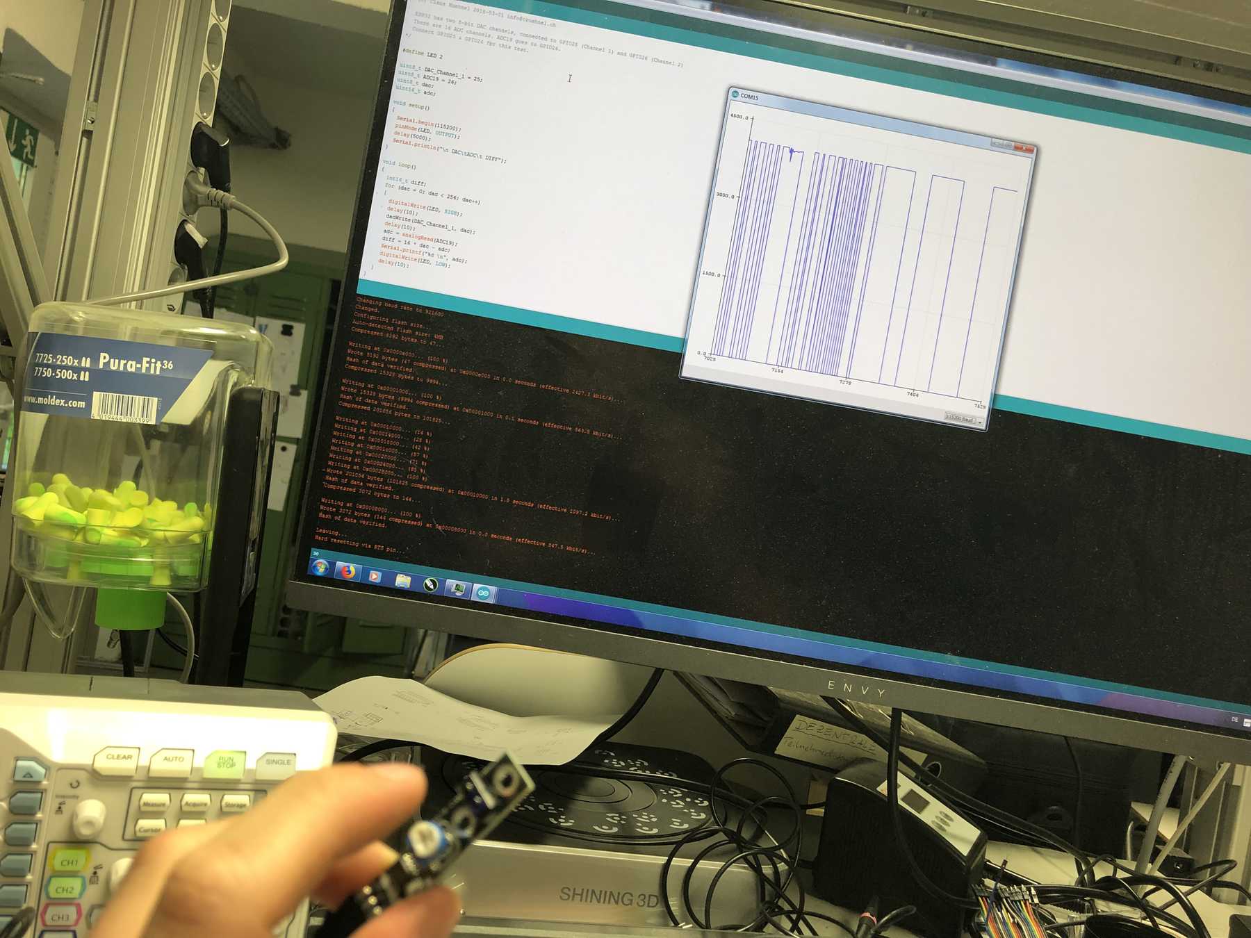
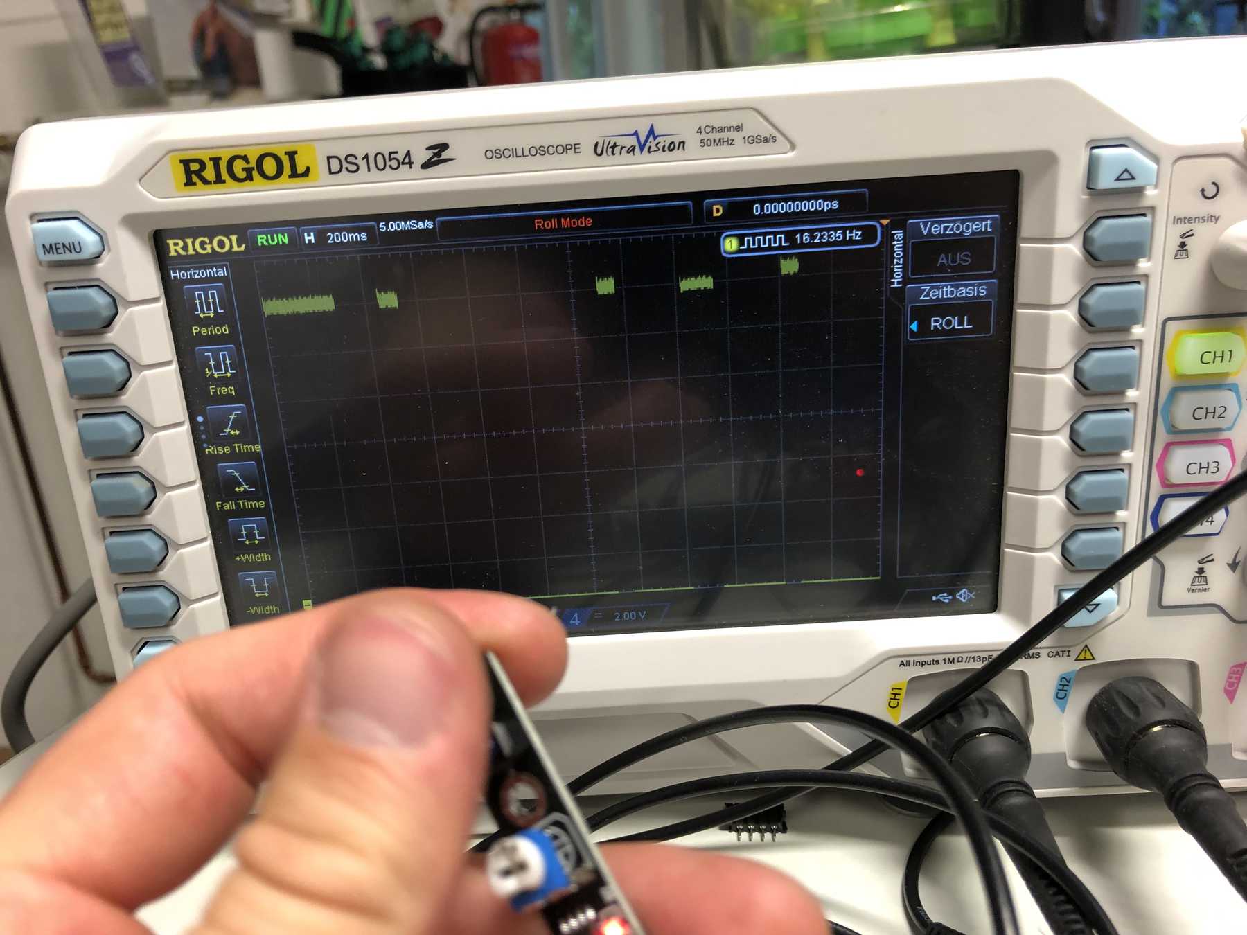
As a digital input device I had the pleasure to measure with an IR distance sensor. I did the measurement directly on the oscilloscope and also used the serial plotter from Arduino for a graphical analysis. You can see that the voltage level changes as soon as it is triggered. On the oscilloscope, we chose the Roll mode to be able to display also a selected range. These then showed recurring measurements, depending on whether the input sensor was measuring something or not.
Individual assignment
Board design
This chapter is divided into two parts. The first part deals with PCB design and can be found in this week. The second part is in output devices week and deals with the manufacturing process with another milling machine.
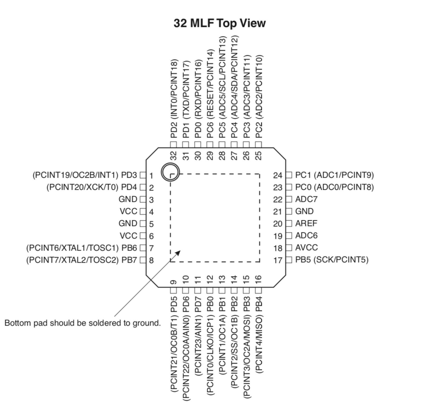
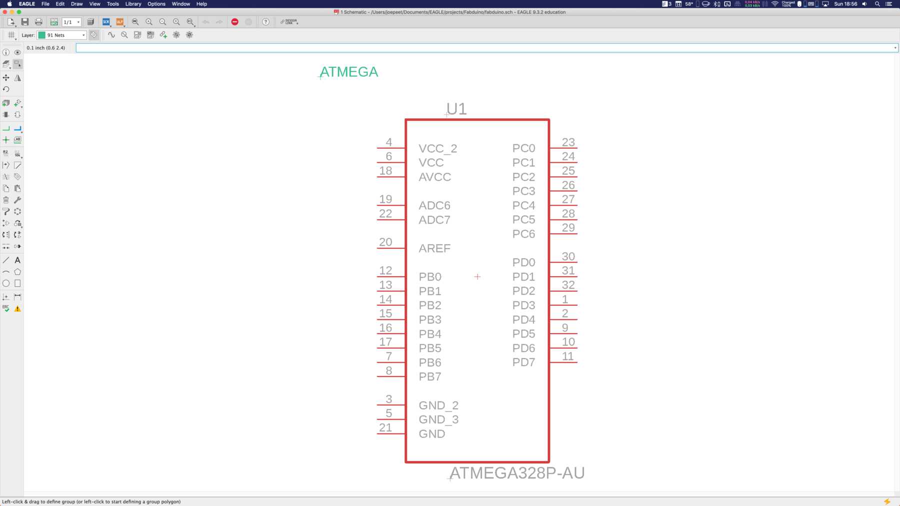
So the first step was to create a new PCB. This board should be so designed that I can use it for input and output devices week, as Niel recommended in his lecture. Therefore I looked at several projects of other students and got stuck at Fabkit. The structure is relatively simple. Only a few capacitors and resistors, a resonator and a button, an LED - that was it. You don’t need more to have an Arduino replica. So nothing else but a minimalized Arduino. If you think ahead, you can theoretically do without almost everything - one possibility to produce a power-saving module. So the thought was: Design your own Arduino board. I looked at the ATmega328P:
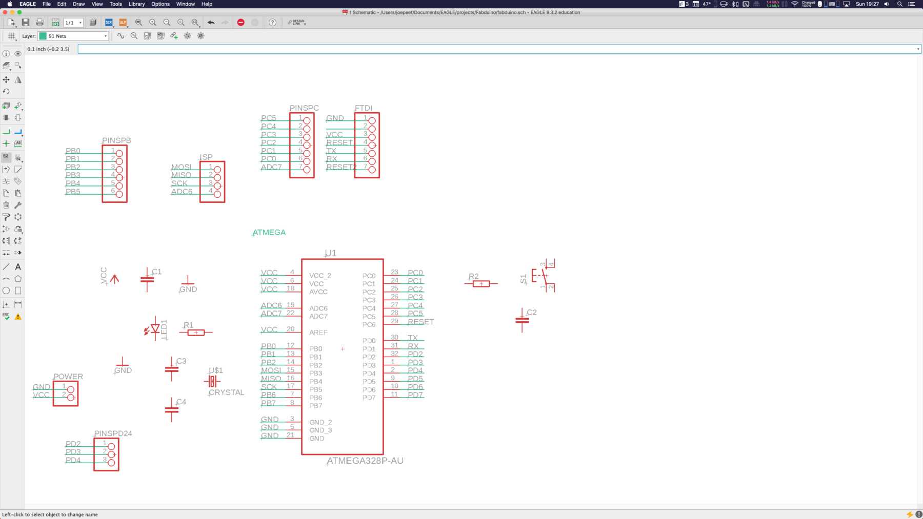
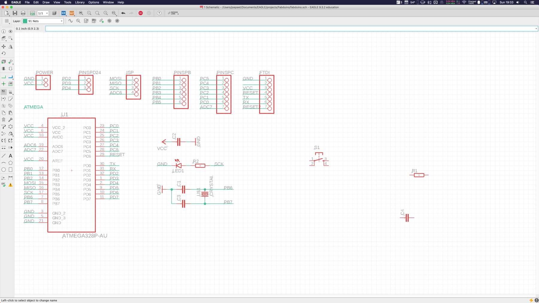
I started working on EAGLE and drew the schematic drawing. I downloaded the necessary footprints for the ATmega328P from element14. The following was created in several stages:
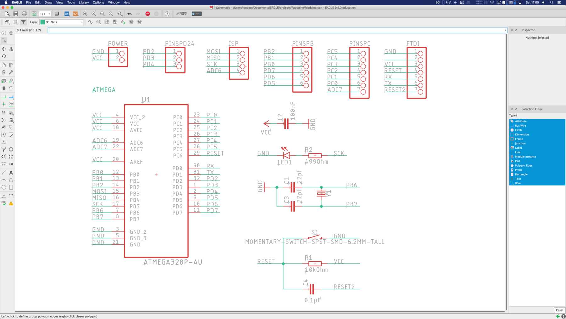
In this assignment, I learned a valuable lesson. Take a close look at which components you have at your place and after that you can start with the drawing or manufacturing. I had to painfully learn how few components are available regionally - despite the fact that I live in an urban area - it’s nearly impossible. The parts list for the board with external 16MHz crystal was as follows:
| Qty | Value | Device | Package | Parts | Description | |
|---|---|---|---|---|---|---|
| 1 | CRYSTALSMD-HC49UP | HC49UP | Y1 | Crystals (Generic) | ||
| 1 | LEDSML1206 | SML1206 | LED1 | LED | ||
| 1 | PINHD-1X2 | 1X02 | POWER | PIN HEADER | ||
| 1 | PINHD-1X3 | 1X03 | PINSPD24 | PIN HEADER | ||
| 1 | PINHD-1X4 | 1X04 | ISP | PIN HEADER | ||
| 1 | PINHD-1X6 | 1X06 | PINSPB | PIN HEADER | ||
| 2 | PINHD-1X7 | 1X07 | FTDI, PINSPC | PIN HEADER | ||
| 2 | 100nF | C-EUC1206 | C1206 | C2,C4 | CAPACITOR, European symbol | |
| 1 | 10kOhm | R-EU_R1206 | R1206 | R1 | RESISTOR, European symbol | |
| 2 | 22pF | C-EUC1206 | C1206 | C1, C3 | CAPACITOR, European symbol | |
| 1 | 499Ohm | R-EU_R1206 | R1206 | R2 | RESISTOR, European symbol | |
| 1 | ATMEGA328P-AU | ATMEGA328P-AU | QFP80P900X900X120-32N | U1 | 8-bit Microcontroller with In-System Programmable Flash - ATMEGA328P-AU | |
| 1 | MOMENTARY-SWITCH-SPST-SMD-6.2MM-TALL | MOMENTARY-SWITCH-SPST-SMD-6.2MM-TALL | TACTILE_SWITCH_SMD_6.2MM_TALL | S1 | Momentary Switch (Pushbutton) - SPST |
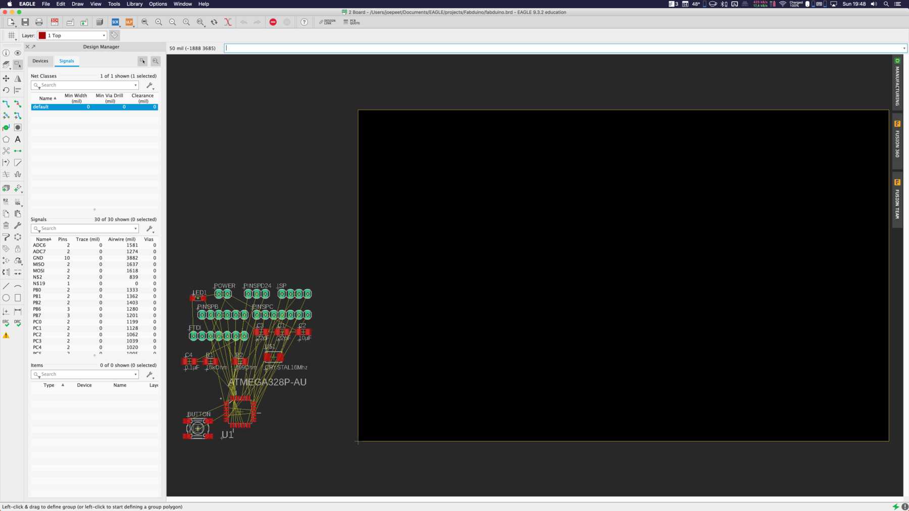
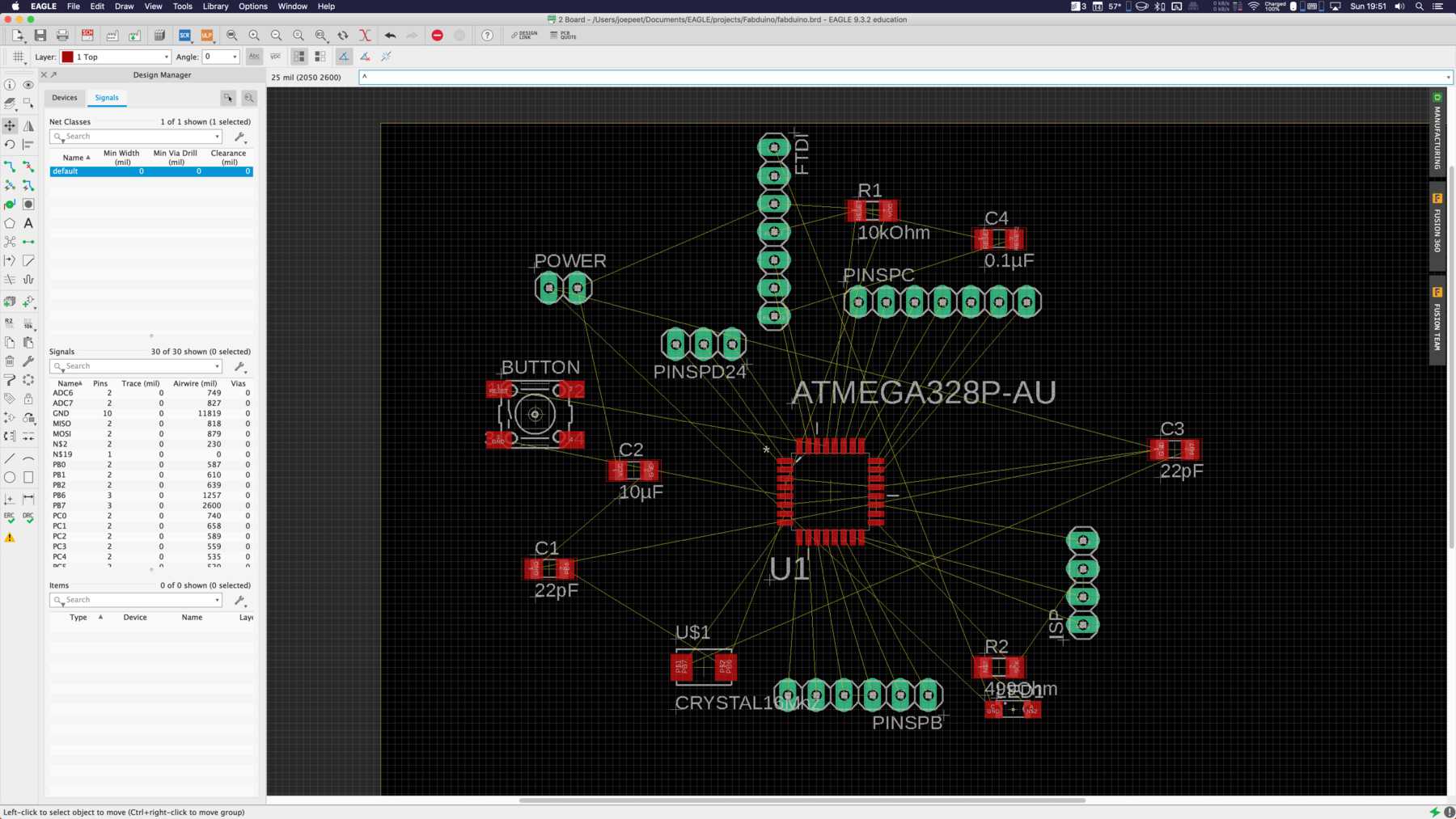
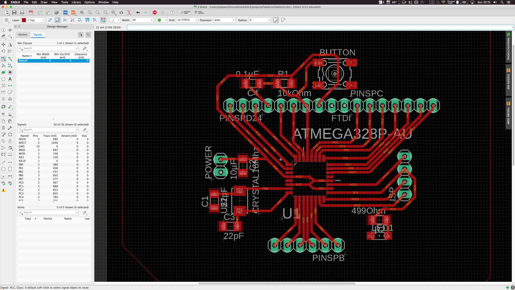
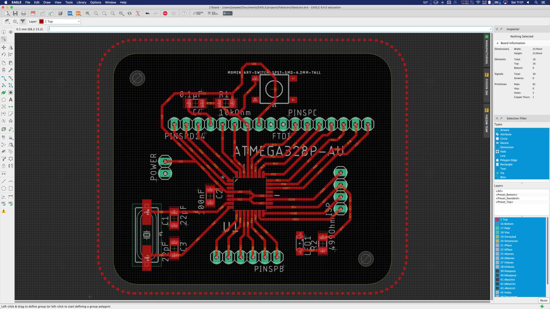
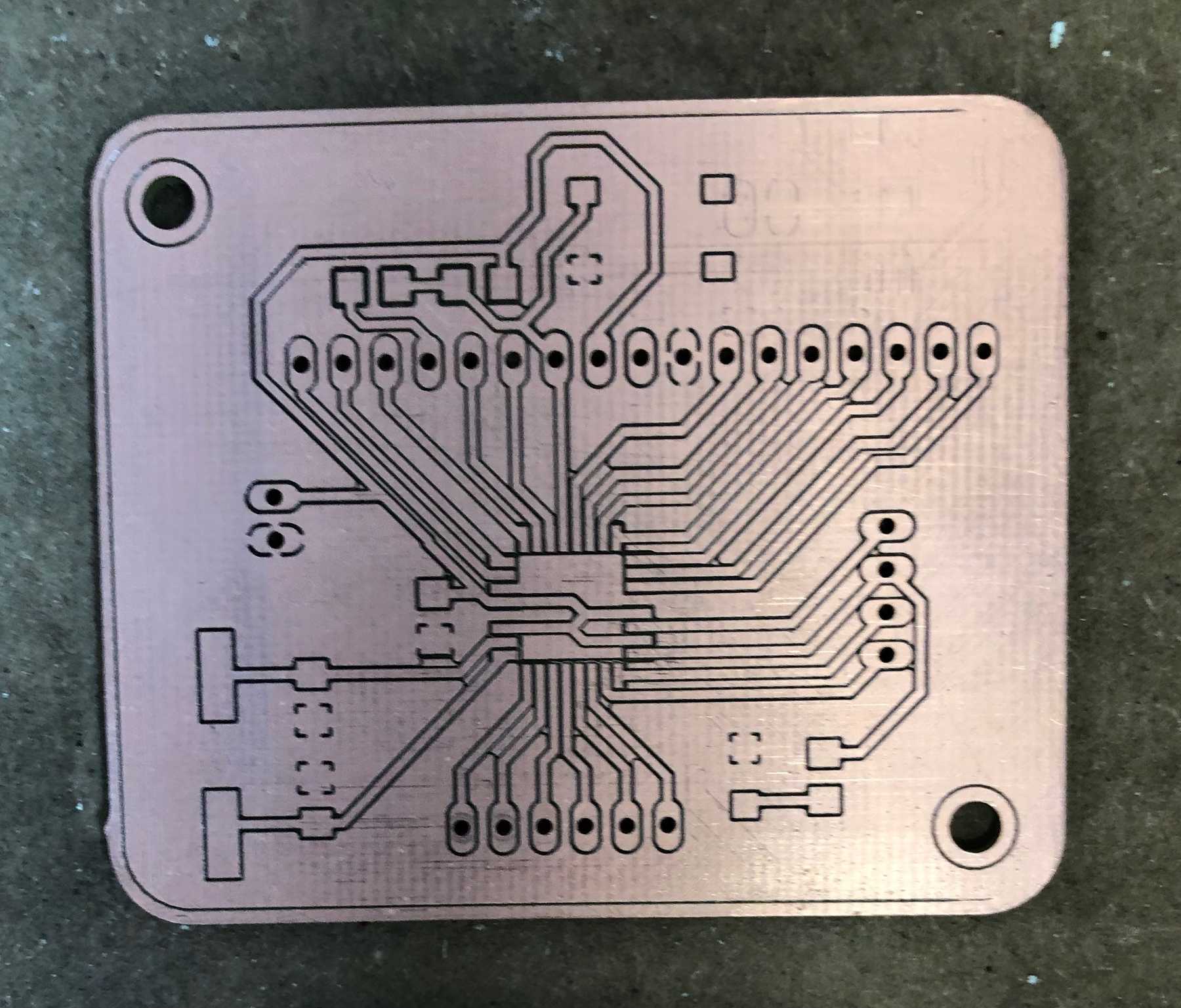
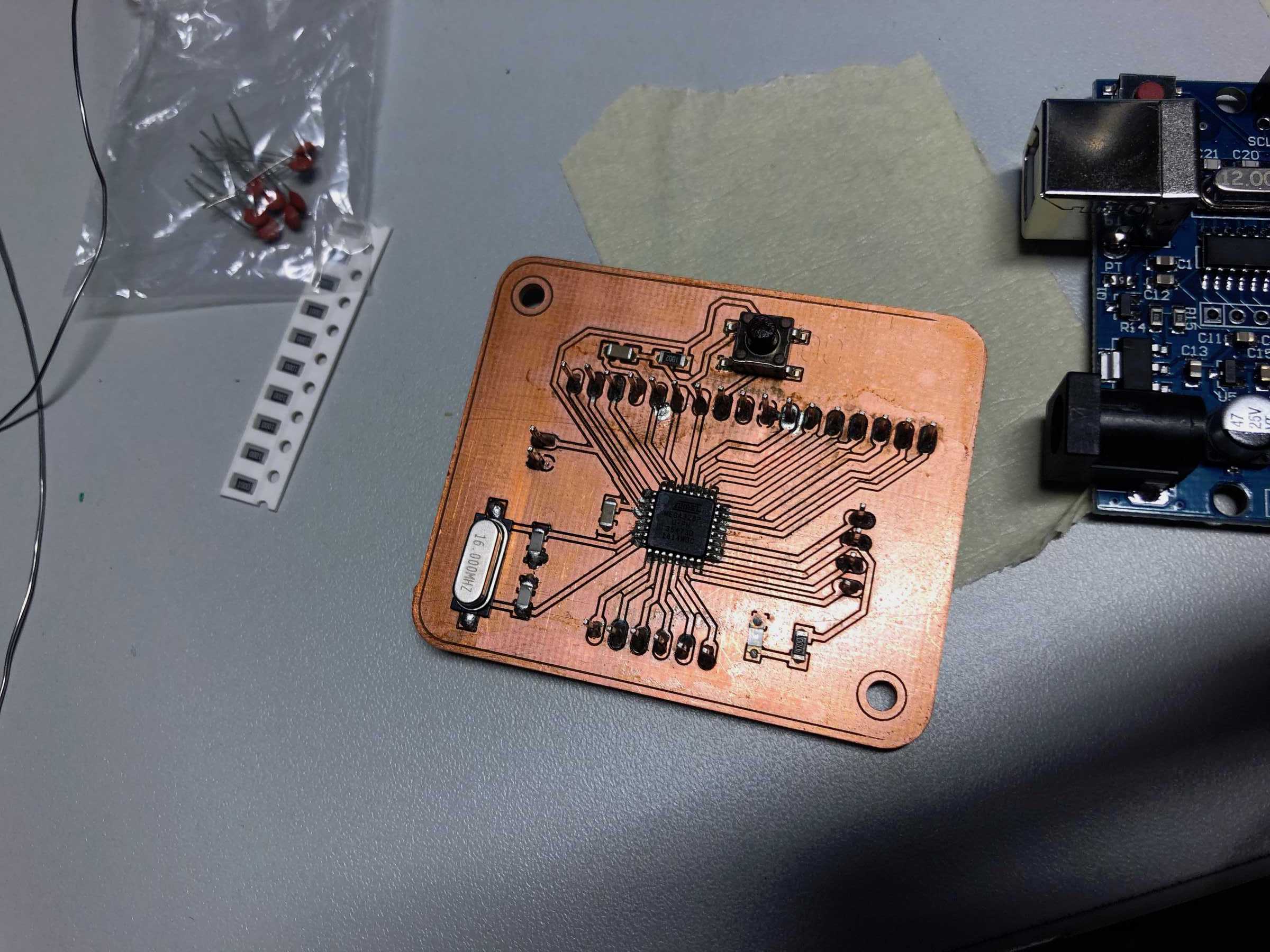
This was followed by the production of the board design. This took some time. Finally the board looked like this - including round corners and holes for mounting:
Afterwards I manufactured it and was allowed to solder all SMD components to it. Solder paste on it, everything in the reflow oven and measure. No connection between GND and VCC?
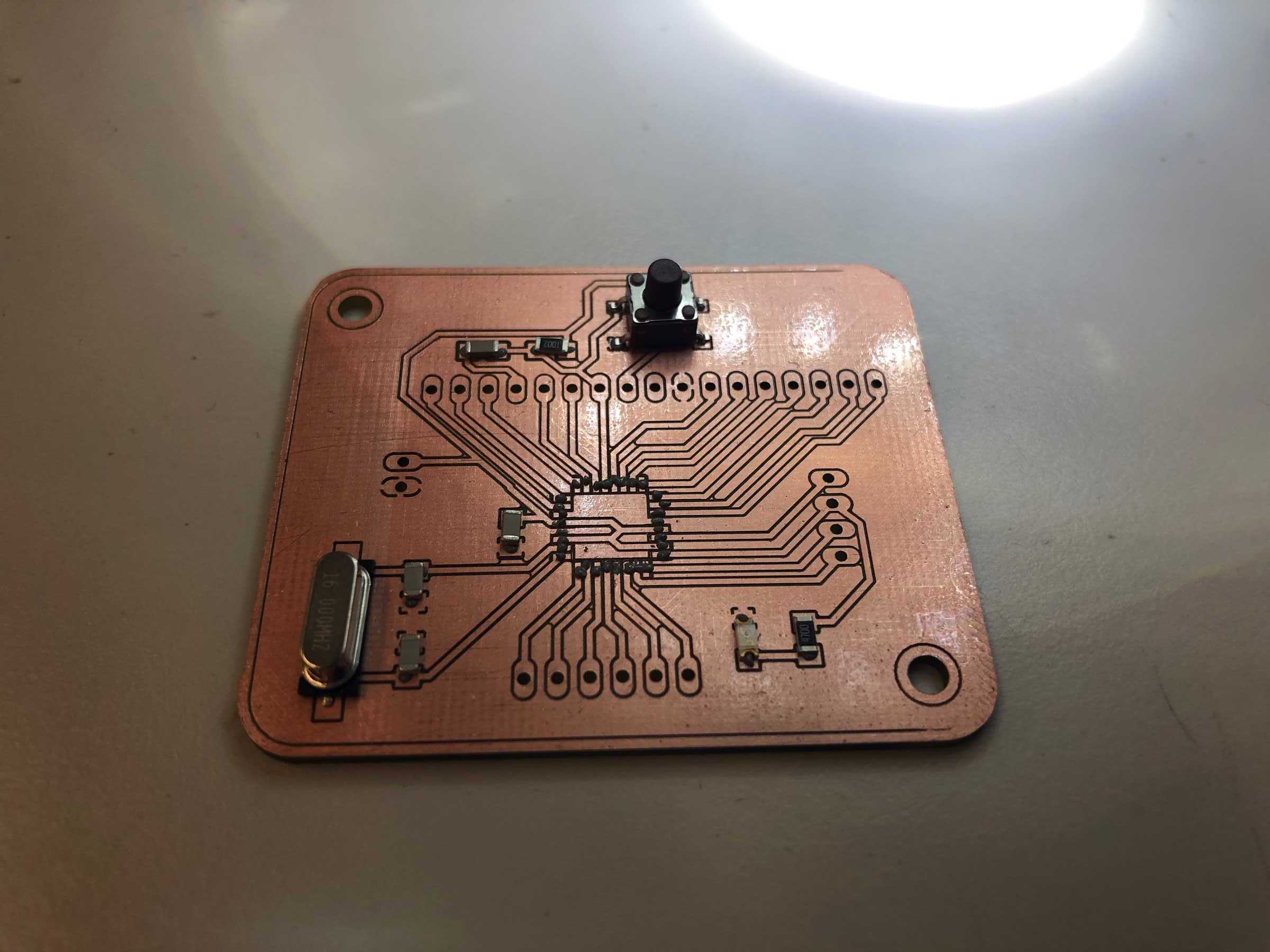
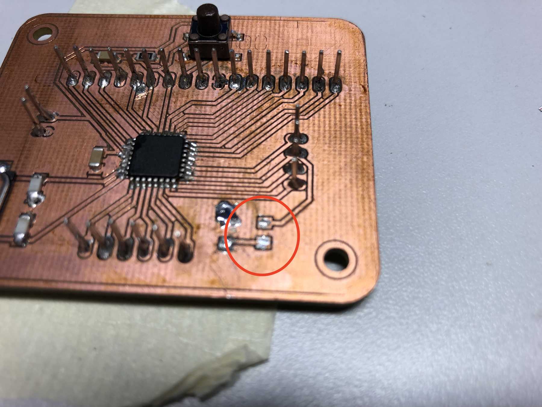
Fortunately I measured everything once again and at one point there was a connection during the check where none should be there. I searched again and identified the resistor as not soldered correctly. Removed and lo and behold:
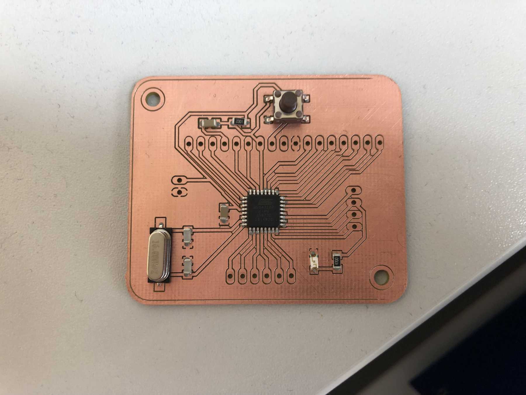
At the end the board looked like that:
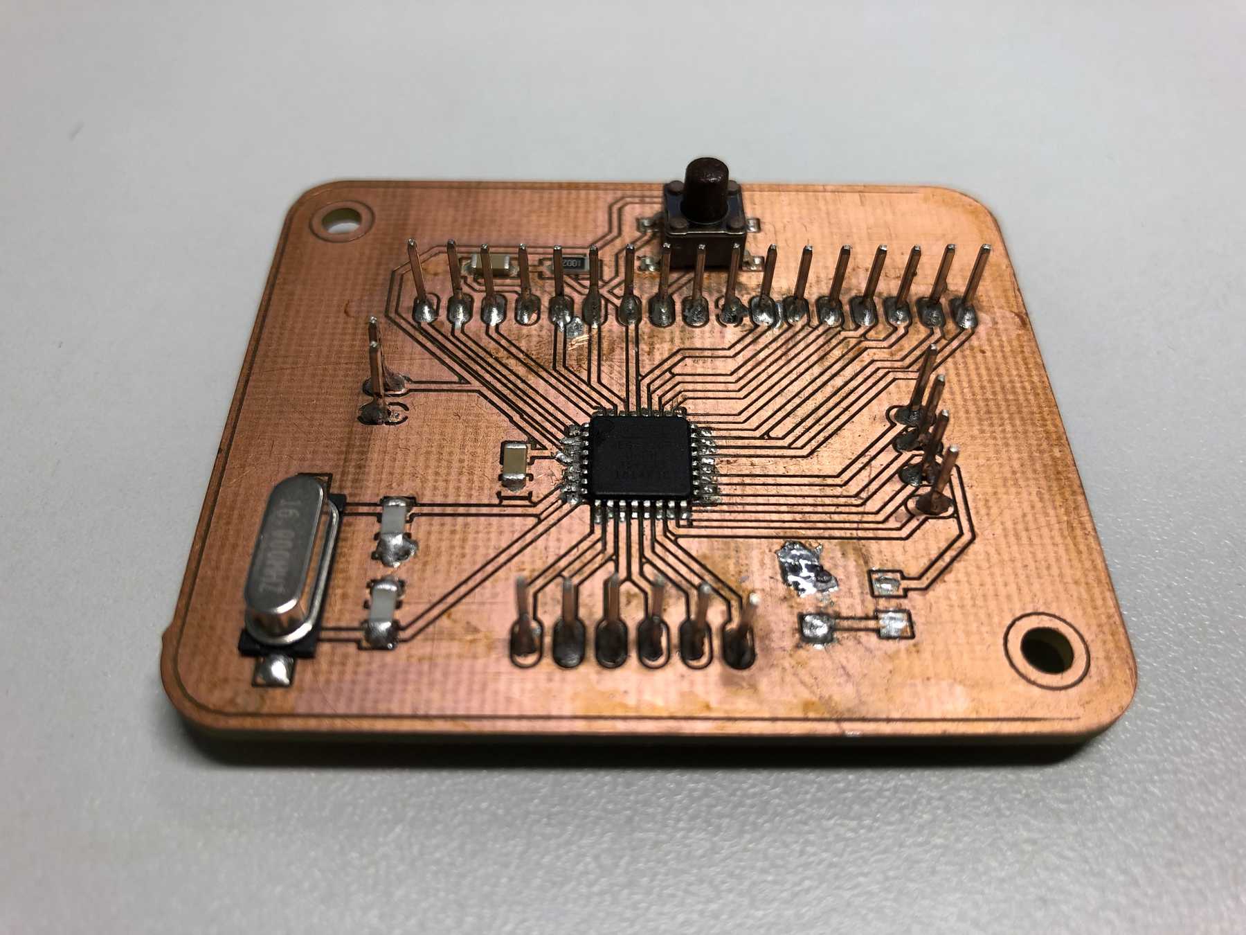
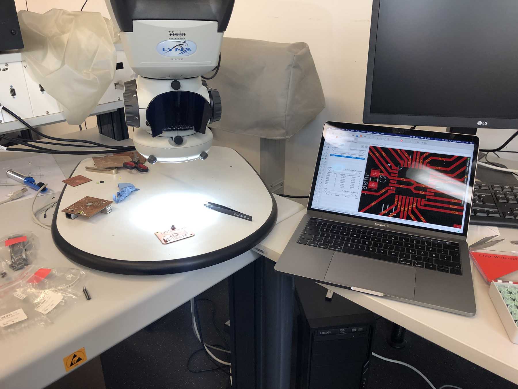
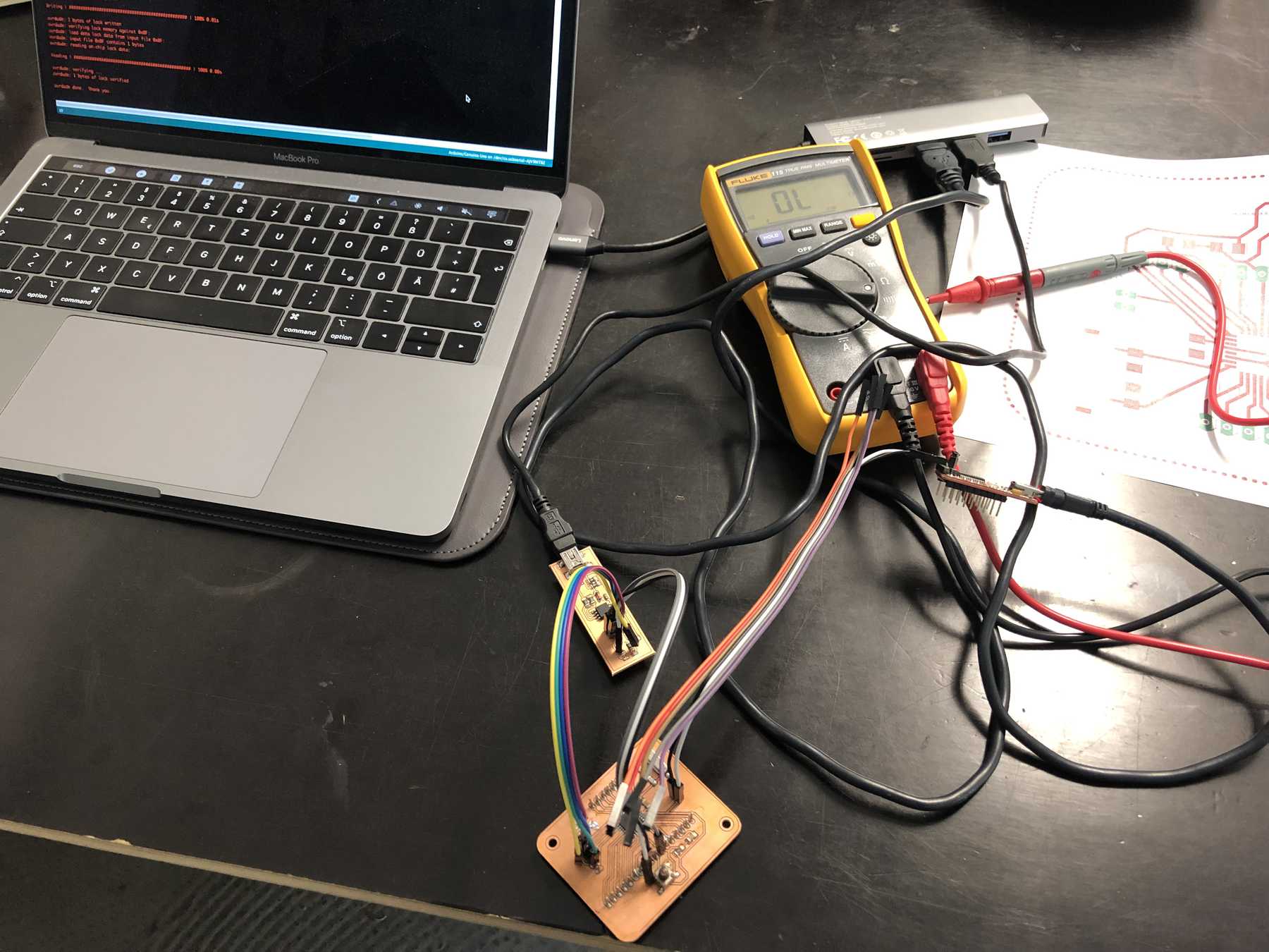
I’ve cleaned this place up. Finally, a few small places were edited again with tools and then I connected the board to the usbtiny. I started the Arduino IDE. As board I chose the Arduino Genuino Uno. The settings can be seen in the following graphic.
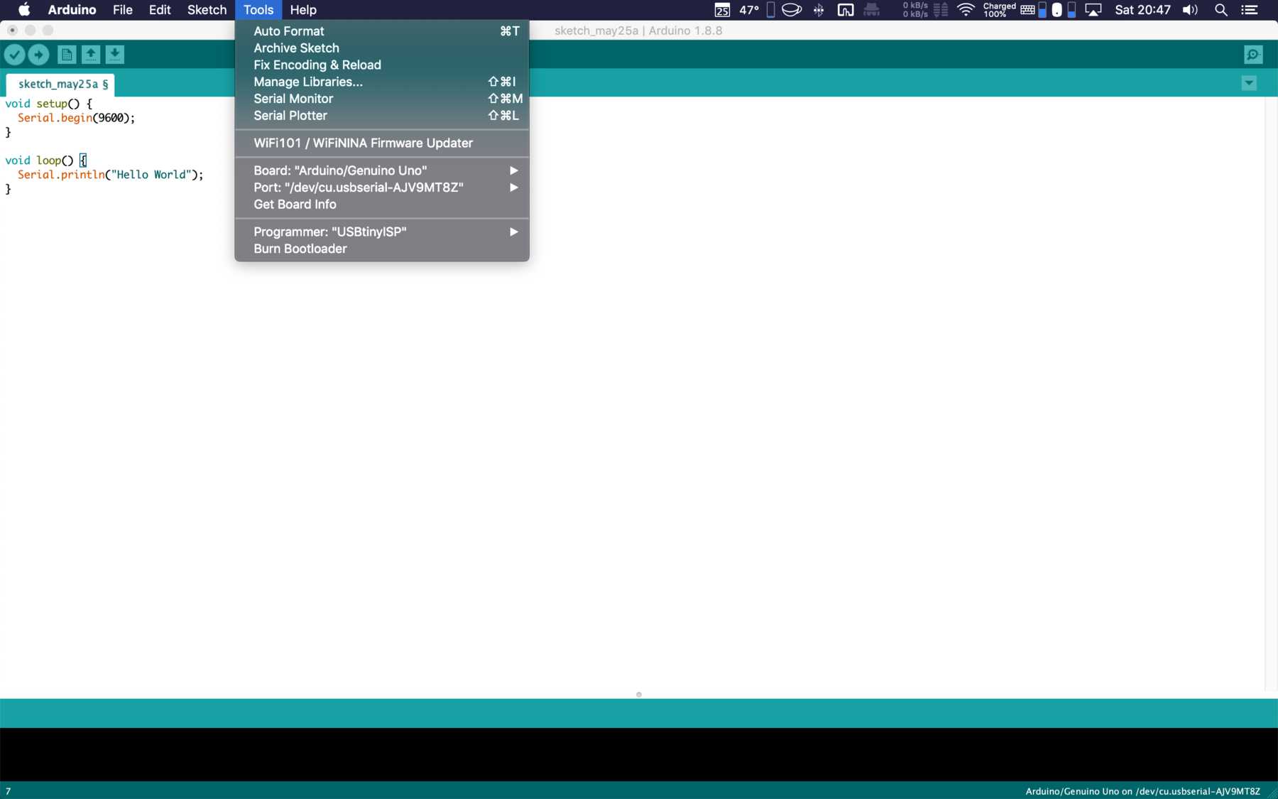
The next step was: Burn bootloader. I put everything together like it is shown on the pictures below. Then a simple sketch to test the serial connection - Does my board work?
void setup() {
  Serial.begin(9600);
}

void loop() {
  Serial.println("Hello World");
}
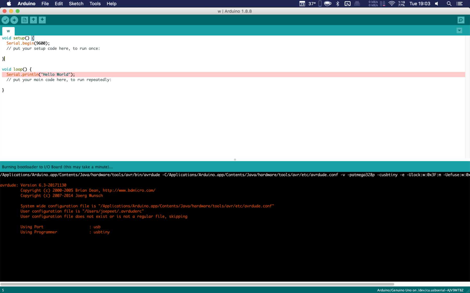
It worked - I was happy!
Mesaure something - Force
In the individual assignment I had the task to measure something with a microcontroller board, which I designed myself. I created the above board as already described, now I had to connect something to the board and measure something. I looked again at the ATmega328P datasheet for it.
Next, I thought about what kind of sensors I need. There are temperature sensor, proximity sensor, accelerometer, IR sensor (infrared sensor), pressure sensor, light sensor, ultrasonic sensor, smoke, gas and alcohol sensor and even more. For my final assignment I need force sensing sensors. These sensors are also available from the company Force Sesnsing Resistor, FSR for short. This company has developed a sensor in the USA that determines the force by changing the electrical resistance. I found a helpful video about Force Sensitive Resistor (FSR) Calibration and Visualization on the channel from Matlab Arduino.
I ordered several different sensors for my final assignment and will probably want to develop something of my own in the end: Depending on the time given to me. I photographed two of them again, the others can be found later in the final assignment.
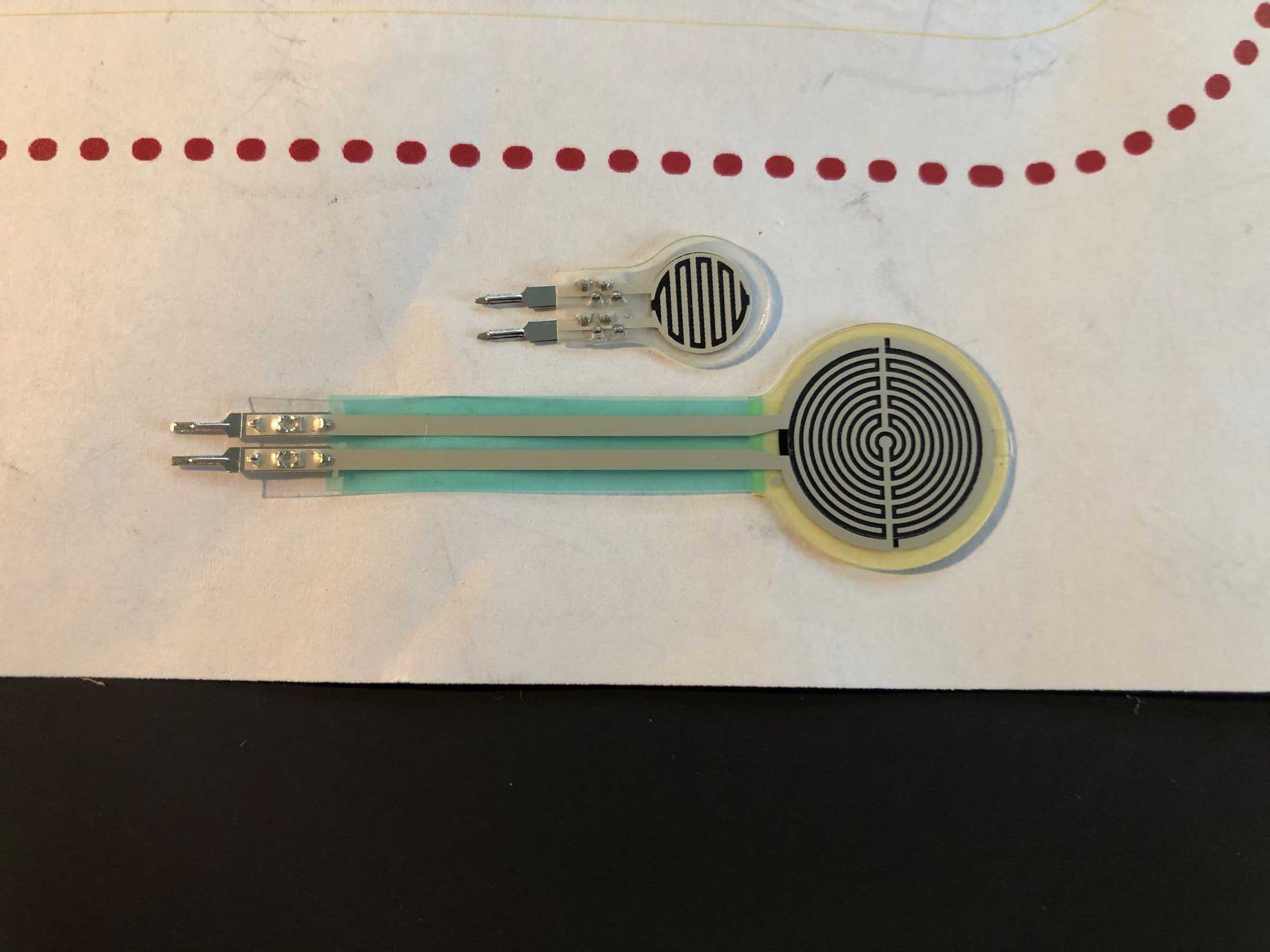
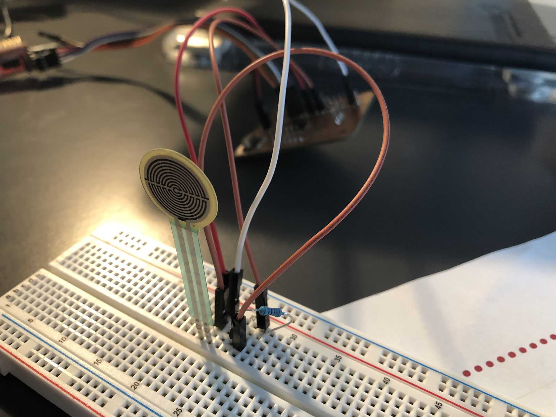
The construction of an FSR is relatively simple: It consists of a sandwich of two plastic films. One is coated on the inside with a semiconducting graphite-containing paste, the other with a comb-shaped interleaved electrically conductive contact grid. However, these two layers are electrically insulated from each other. Only when an external force acts on the FSR does a contact occur and thus an active electrical connection. As a result, an electrical resistance can then be measured in ohms.
From the small pressure sensor I could take the following data from the dealer side:
- Measuring Range: 0~10kg
- Thickness: <0.25mm
- Response Point: <20g
- Repeatability: <±4.1%(50% load)
- Precision: ±2.5%
- Lifespan: >1million times
- Initial Resistance: >10MΩ(no load)
- Response Time: <1ms
- Restore Time: <15ms
- Test Voltage: DC 3.3V (typical)
- Operating Temperature: -20℃ ~ 60℃
I could find a very good manual for the Force Sensitive Resistor (FSR) at Sparkfun. Another good tutorial can be found here at ladyada. There are also graphs in the manual that represent the resistance to the force.
I got the sketch from the <a href=”https://learn.adafruit.com/force-sensitive-resistor-fsr/using-an-fsr” target=”_blank” adafruit and them got it from the mentioned source in the sketch:
/* FSR testing sketch.

Connect one end of FSR to 5V, the other end to Analog 0.
Then connect one end of a 10K resistor from Analog 0 to ground
Connect LED from pin 11 through a resistor to ground

For more information see www.ladyada.net/learn/sensors/fsr.html */

int fsrAnalogPin = 0; // FSR is connected to analog 0
int LEDpin = 11;      // connect Red LED to pin 11 (PWM pin)
int fsrReading;      // the analog reading from the FSR resistor divider
int LEDbrightness;

void setup(void) {
  Serial.begin(9600);   // We'll send debugging information via the Serial monitor
  pinMode(LEDpin, OUTPUT);
}

void loop(void) {
  fsrReading = analogRead(fsrAnalogPin);
  Serial.print("Analog reading = ");
  Serial.println(fsrReading);

  // we'll need to change the range from the analog reading (0-1023) down to the range
  // used by analogWrite (0-255) with map!
  LEDbrightness = map(fsrReading, 0, 1023, 0, 255);
  // LED gets brighter the harder you press
  analogWrite(LEDpin, LEDbrightness);

  delay(100);
}
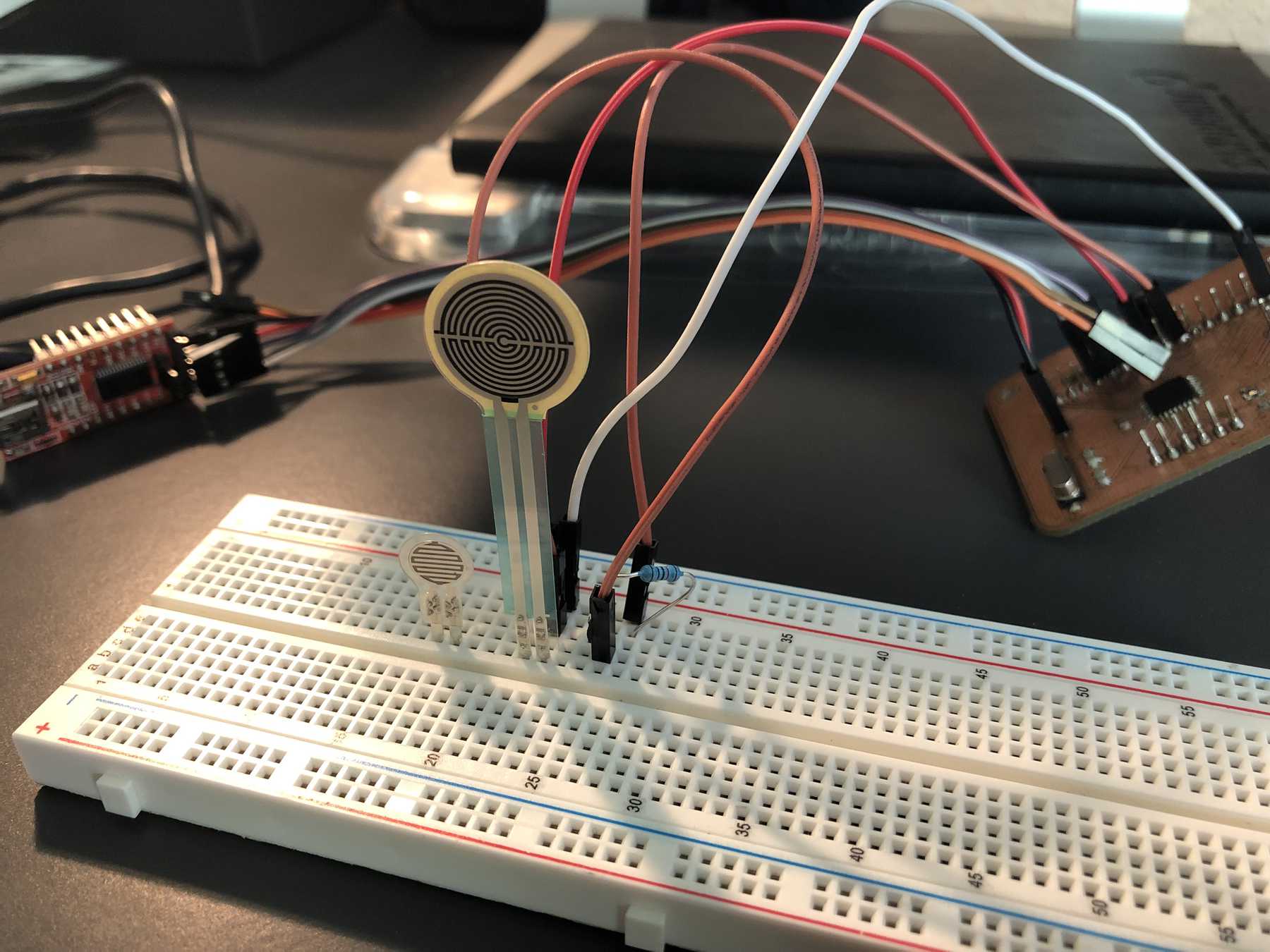
I placed the sensor on the breadboard. One side connected to 5V. The other side with GND and a 10KOhm resistor as well as the analog pin 0. Finally I uploaded the sketch via the Arduino IDE to the ATmega328P and the following video shows the result.
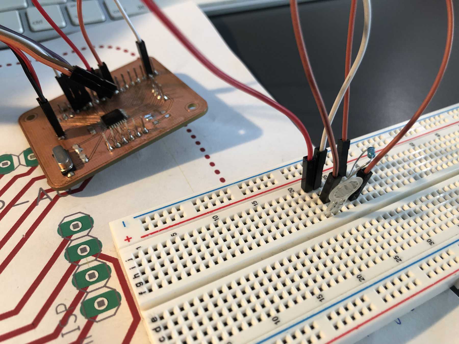
To get a more accurate impression, I made the following video:
Everything worked well and I was happy.
Mesaure something - Gyro
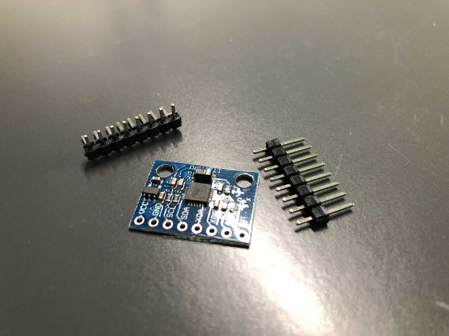
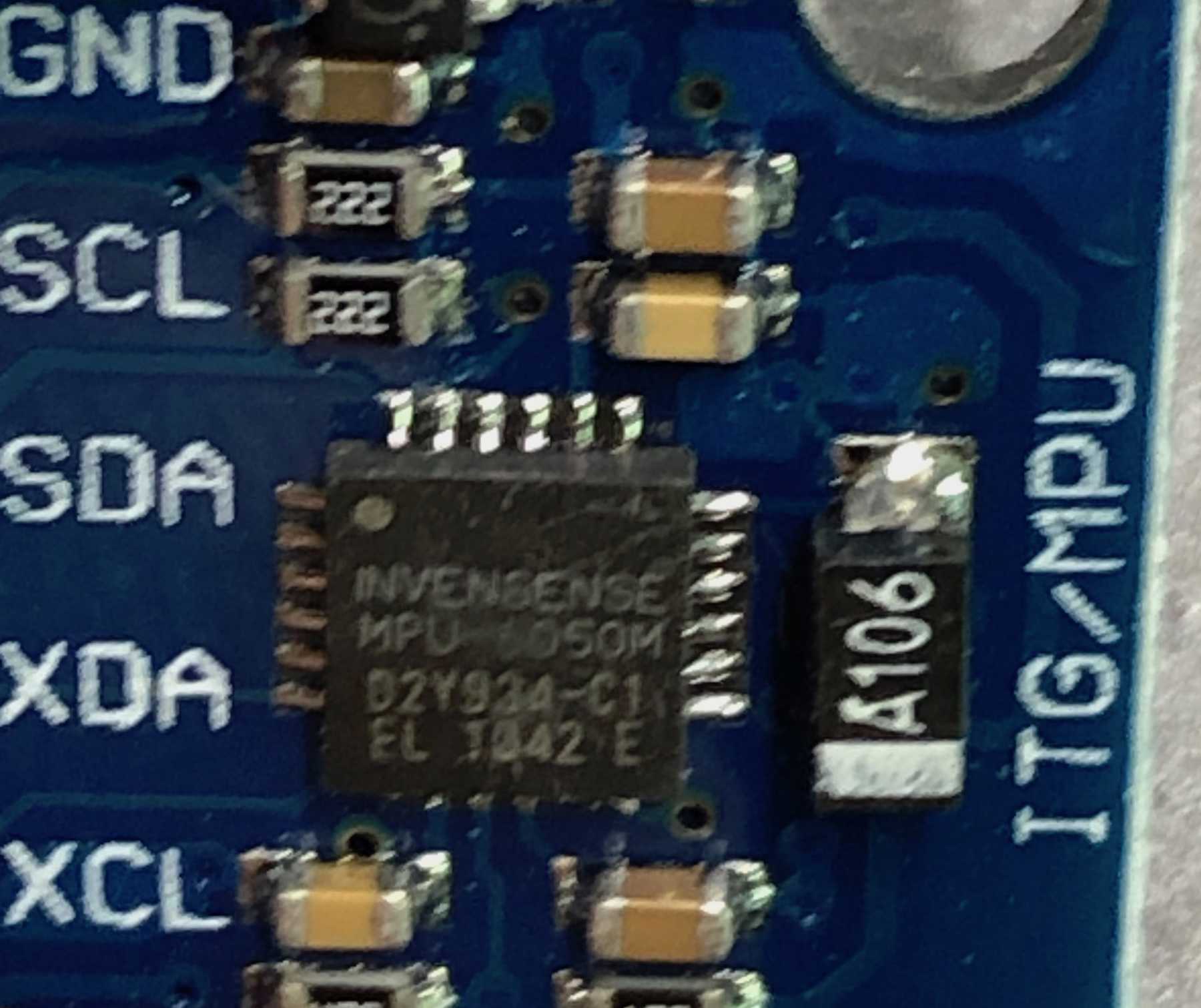
Next I wanted to try a gyroscope as a sensor which I will need for the machine building week and maybe for the final project. I ordered the GY-521, a break-out board for the MPU-6050 MEMS, which is a six-axis (3 axis gyro, 3 axis accelorometer) MEMS sensing device for low power and low cost devices. In the past, I have studied the basics of MEMS, the working principle of MEMS and how it is manufactured. A visually appealing video explaining the working principle of a gyroscope is from Bosch. The GY-521 module has an external appearance as follows:
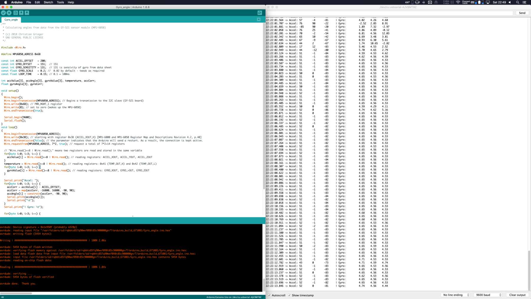
Through some searching I came across a very informative tutorial, which is tailored for the Arduino application. I took a closer look at this tutorial and tried to understand how exactly the measured values are calculated. The sketch and the manual are from the website turanis and from the github page griegerc. Another helpful tutorial could befound on the personal website from Michael Schoeffler. The Arduino sketch looked like this:
/**
 * Calculating angles from data from the GY-521 sensor module (MPU-6050)
 *
 * (c) 2018 Christian Grieger
 * GNU GENERAL PUBLIC LICENSE
 */

#include <Wire.h>

#define MPU6050_ADRESS 0x68

const int ACCEL_OFFSET   = 200;
const int GYRO_OFFSET    = 151;  // 151
const int GYRO_SENSITITY = 131;  // 131 is sensivity of gyro from data sheet
const float GYRO_SCALE   = 0.2; //  0.02 by default - tweak as required
const float LOOP_TIME    = 0.15; // 0.1 = 100ms

int accValue[3], accAngle[3], gyroValue[3], temperature, accCorr;
float gyroAngle[3], gyroCorr;

void setup()
{
  Wire.begin();
  Wire.beginTransmission(MPU6050_ADRESS); // Begins a transmission to the I2C slave (GY-521 board)
  Wire.write(0x6B); // PWR_MGMT_1 register
  Wire.write(0); // set to zero (wakes up the MPU-6050)
  Wire.endTransmission(true);

  Serial.begin(9600);
  Serial.flush();
}
void loop()
{
  Wire.beginTransmission(MPU6050_ADRESS);
  Wire.write(0x3B); // starting with register 0x3B (ACCEL_XOUT_H) [MPU-6000 and MPU-6050 Register Map and Descriptions Revision 4.2, p.40]
  Wire.endTransmission(false); // the parameter indicates that the Arduino will send a restart. As a result, the connection is kept active.
  Wire.requestFrom(MPU6050_ADRESS, 7*2, true); // request a total of 7*2=14 registers

  // "Wire.read()<<8 | Wire.read();" means two registers are read and stored in the same variable
  for(byte i=0; i<3; i++) {
    accValue[i] = Wire.read()<<8 | Wire.read(); // reading registers: ACCEL_XOUT, ACCEL_YOUT, ACCEL_ZOUT
  }
  temperature = Wire.read()<<8 | Wire.read(); // reading registers: 0x41 (TEMP_OUT_H) and 0x42 (TEMP_OUT_L)
  for(byte i=0; i<3; i++) {
    gyroValue[i] = Wire.read()<<8 | Wire.read(); // reading registers: GYRO_XOUT, GYRO_>OUT, GYRO_ZOUT
  }

  Serial.print("Accel: ");
  for(byte i=0; i<3; i++) {
    accCorr = accValue[i] - ACCEL_OFFSET;
    accCorr = map(accCorr, -16800, 16800, -90, 90);
    accAngle[i] = constrain(accCorr, -90, 90);
    Serial.print(accAngle[i]);
    Serial.print("\t");
  }
  Serial.print("| Gyro: \t");

  for(byte i=0; i<3; i++) {
    gyroCorr = (float)((gyroValue[i]/GYRO_SENSITITY) - GYRO_OFFSET);
    gyroAngle[i] = (gyroCorr * GYRO_SCALE) * -LOOP_TIME;
    Serial.print(gyroAngle[i]);
    Serial.print("\t");
  }

  Serial.println(" ");
  delay(LOOP_TIME * 1000);
}
I connected all the components together and made sure I used the right pins on my own board.
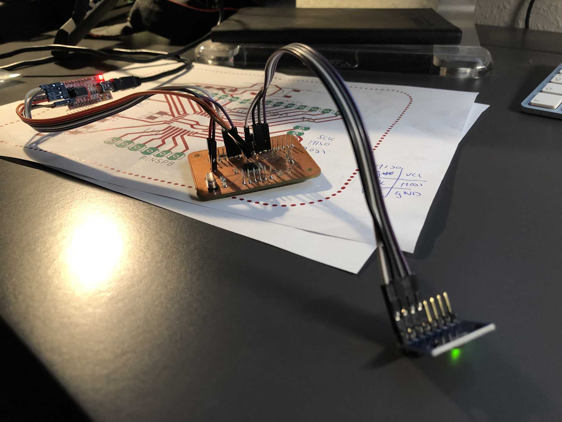
In the end, everything worked again and the video was created during that time:
Here you can download the files mentioned above:
EAGLE files of the fabduino-board