Networking and Communications
Week 14
This week deals with networking and communications. My assignment was to design, build and network my own board, either via network or bus addresses. At the end I was supposed to send a message in my group assignment between two projects.
Individual assignment
ESP32 board
New week, new board. But what kind? This week the requirements were high and for me even higher. I wanted to design a low power board, which ideally contains all standards. The selection gets smaller and I always stumbled across the ESP32 board. Why not design my own ESP32 board? Here we go.
First I have a look at what boards are currently available at mouser and which ones I could use. I found an ESP32-WROVER-IB with WLAN modules (802.11) SMD modules, ESP32-D0WD, 64Mbits PSRAM, 128Mbits SPI flash and IPEX Antenna connector. It not only supports WLAN in the 2.4 GHZ range, but also Bluetooth. The operating voltage is 3.3 V and there is sufficient Arduino IDE support with many libraries.
As a next step, I took a look at the datasheet and thought about what is necessary to make the design as minimalistic as possible while still making it work. I can do without LEDs. A USB port or similar is also not necessary. It just has to be bootable and useable. The necessary requirements could be found in the datasheet. I looked at other ESP32 designs on the internet and compared them. On page 15 I found the following schematic drawing in the datasheet.
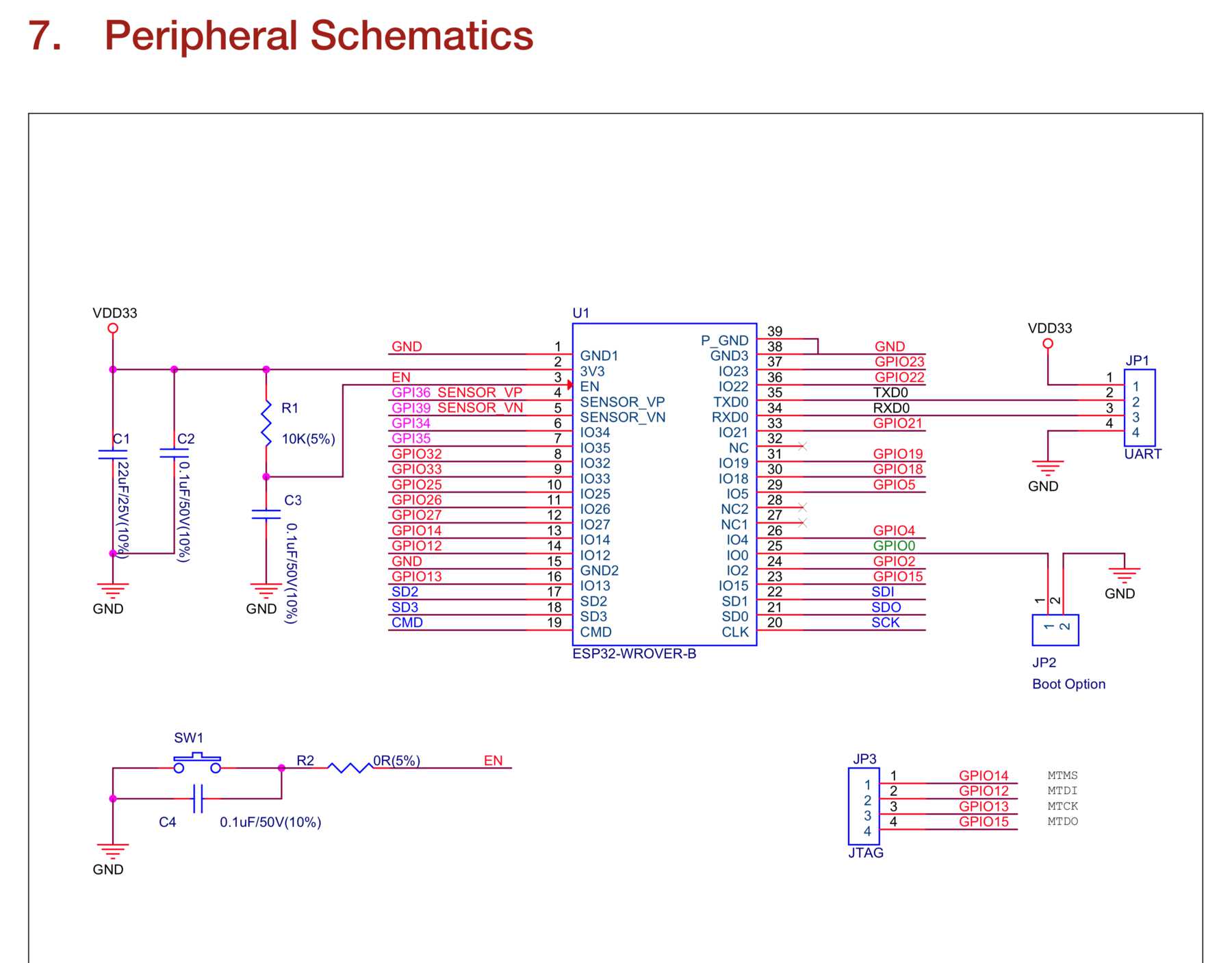
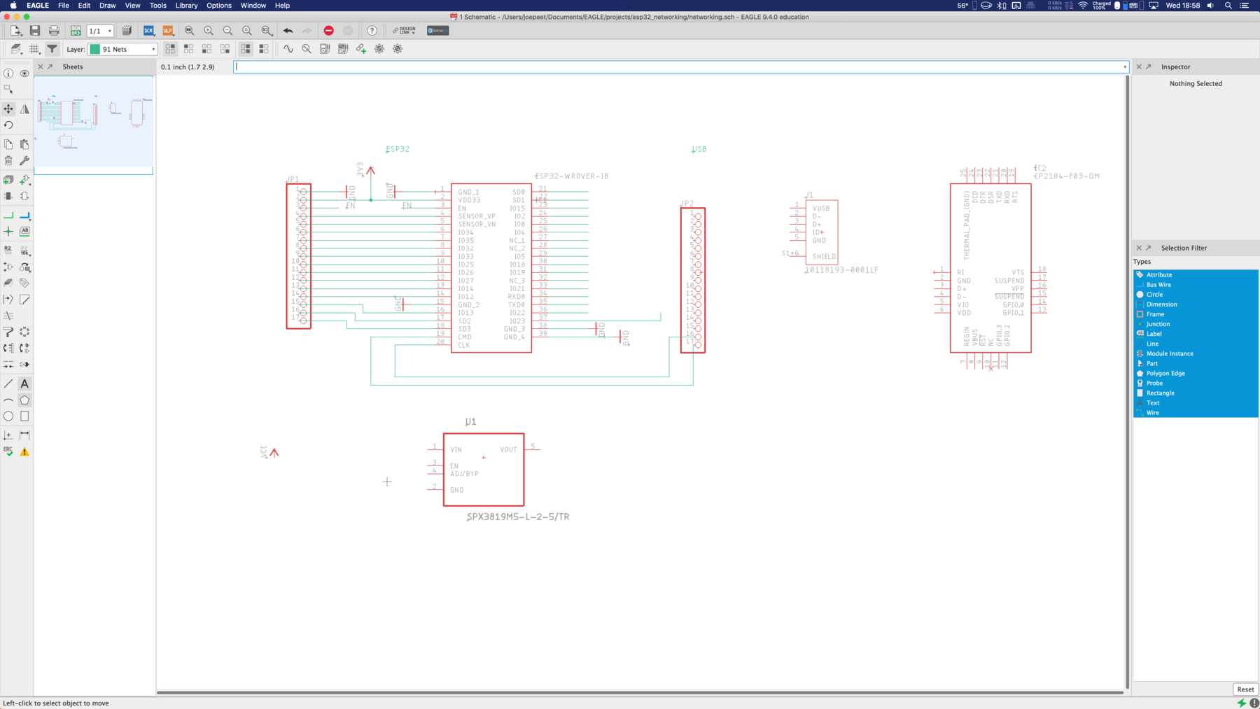
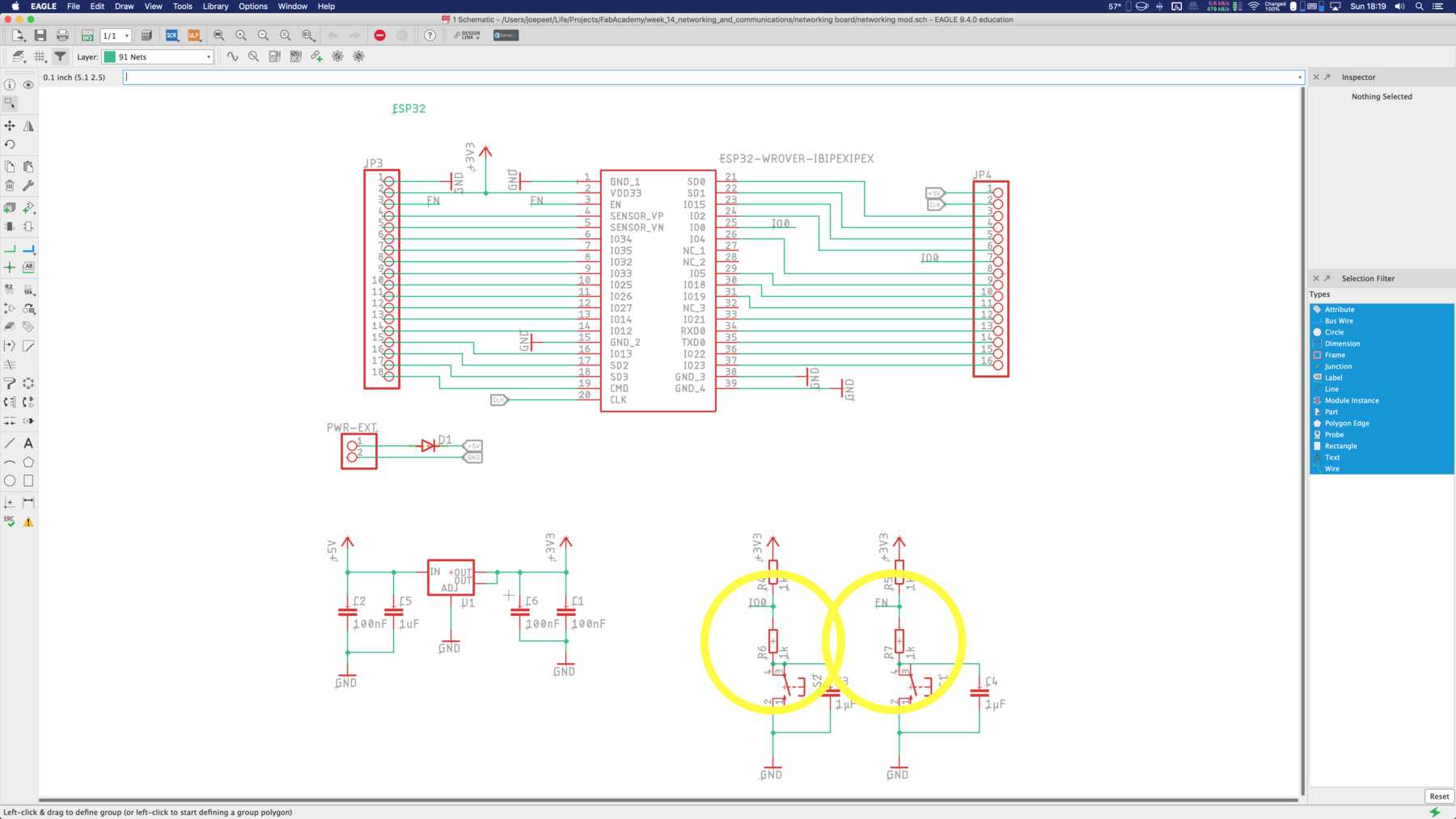
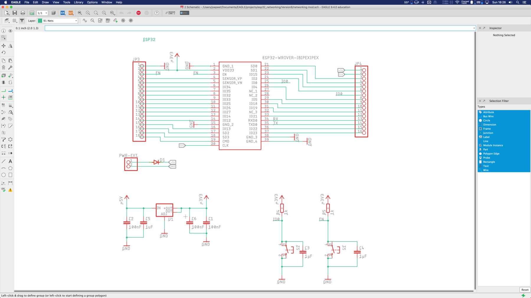
Now it was time for my own drawing, one by one, to my own ESP32 design. The components were added and it was always paid attention that all components are present at the FabLab.
The parts list was accordingly very well arranged for a low power board:
| Qty | Value | Device | Package | Parts | Description |
|---|---|---|---|---|---|
| 2 | 10-XX | B3F-10XX | S1, S2 | OMRON SWITCH | |
| 1 | DIODE-SOD123 | SOD123 | D1 | DIODE | |
| 1 | PINHD-1X16 | 1X16 | JP4 | PIN HEADER | |
| 1 | PINHD-1X18 | 1X18 | JP3 | PIN HEADER | |
| 1 | PINHD-1X2/90 | 1X02/90 | PWR-EXT | PIN HEADER | |
| 1 | V_REG_LM1117SOT223 | SOT223 | U1 | Voltage Regulator LM1117 | |
| 3 | 100nF | C-EUC1206 | C1206 | C1, C2, C6 | CAPACITOR, European symbol |
| 2 | 1k | R-EU_R1206 | R1206 | R4, R5 | RESISTOR, European symbol |
| 1 | 1uF | C-EUC1206 | C1206 | C5 | CAPACITOR, European symbol |
| 2 | 1µF | C-EUC1206 | C1206 | C3, C4 | CAPACITOR, European symbol |
| 1 | ESP32-WROVER-IBIPEXIPEX | ESP32-WROVER-IBIPEXIPEX | ESP32-WROVER-IB | IC1 | WiFi Modules (802.11) SMD Module, ESP32-D0WD, 64Mbits PSRAM, 32Mbits SPI flash, IPEX Antenna connector |
Intermediate conclusion: Only a few components because I do not use many components that consume a lot of energy. This means I use an FTDI. Of course I have to make sure later that the voltage is set to 3.3 V for this board and not for 5 V. I found a good description and evaluation of the ESP32 module at Tom Erweller.
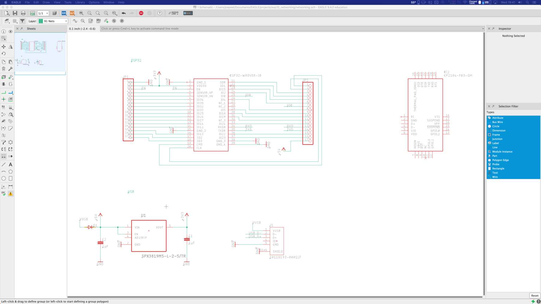
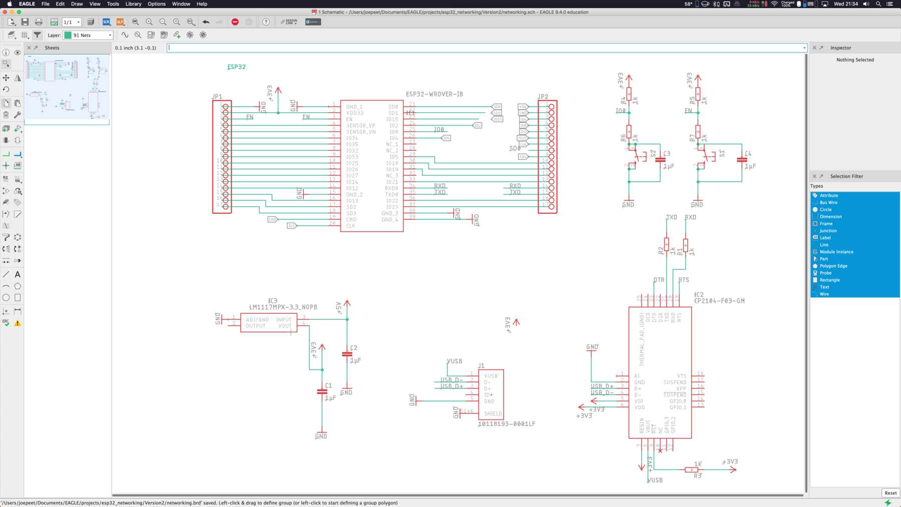
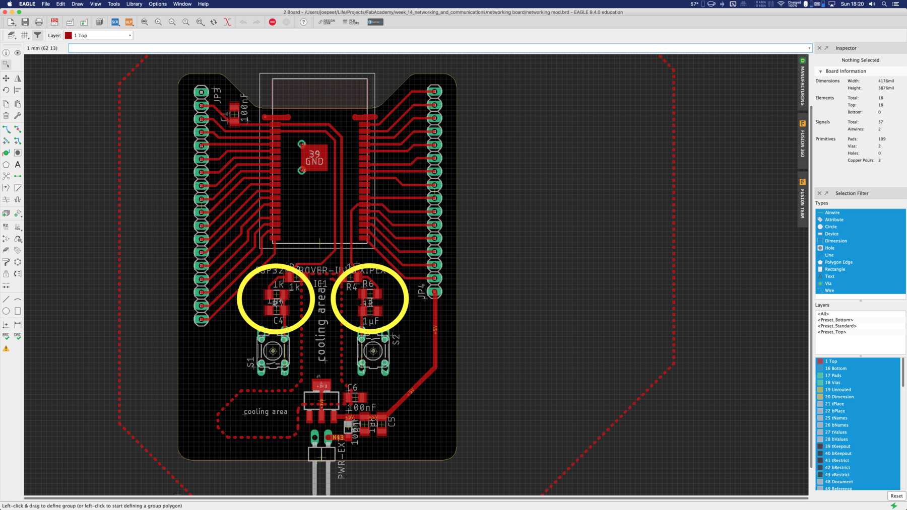
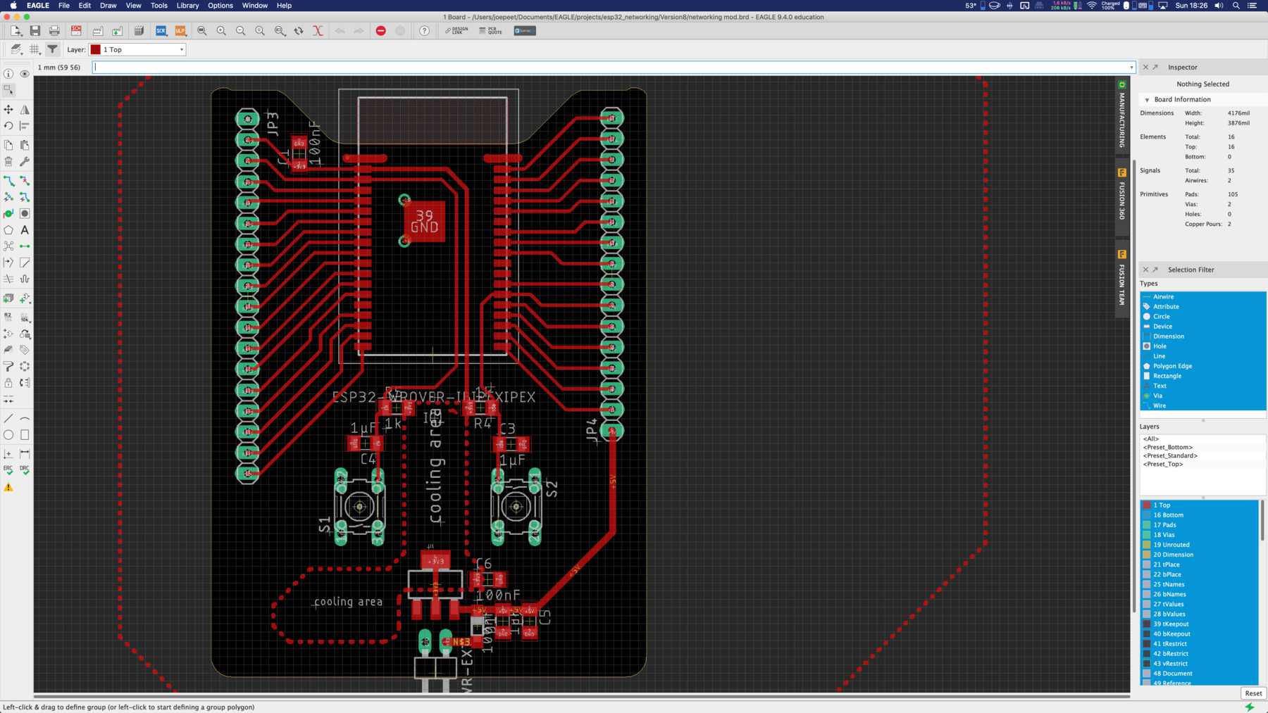
After that I went to the board design, where I did several iterations. On the internet you can read that the ESP32 module can have temperature problems. I wasn’t sure if it was true, also the inner temperature sensor was switched off sometime. Nevertheless I wanted to be on the safe side and designed my ESP32 accordingly.
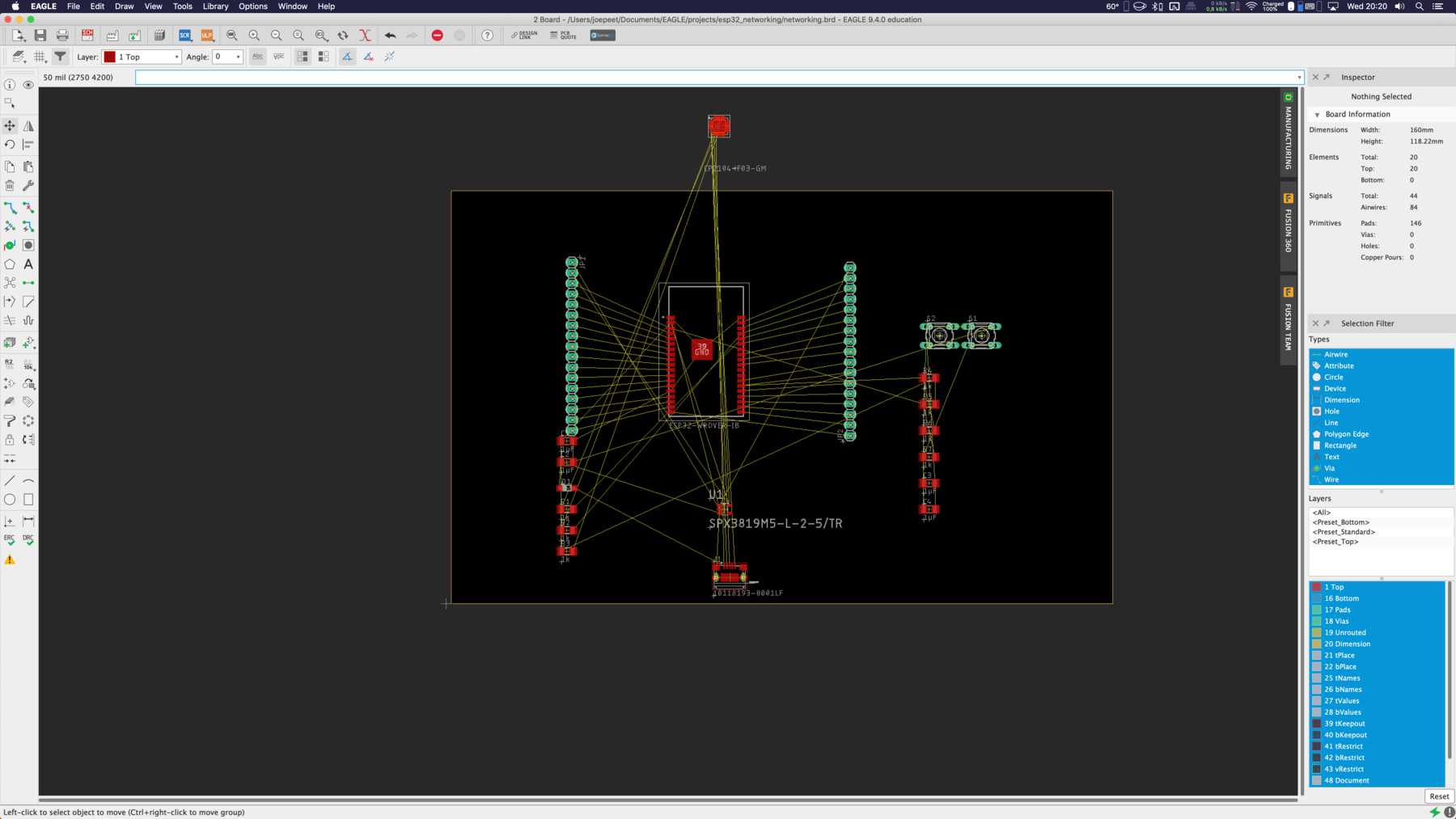
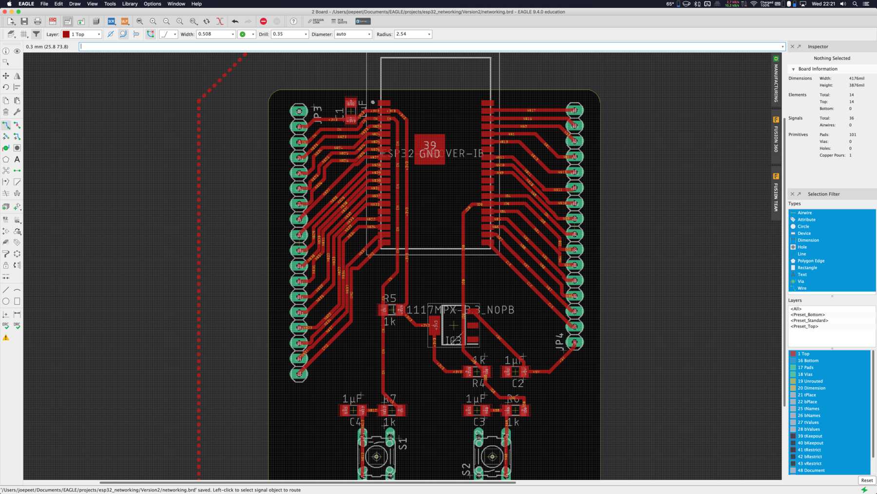
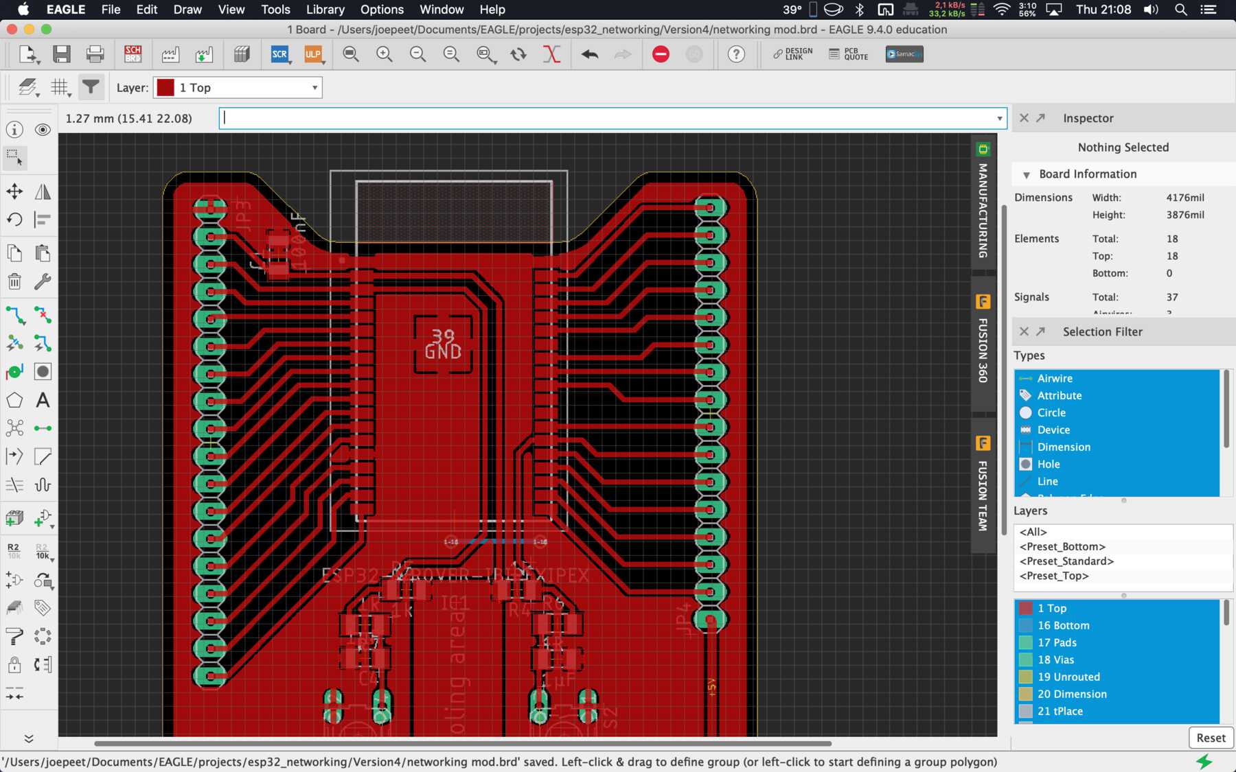
Unfortunately there was a bug with the board design. I had a resistance of 1k Ohm too much on the button trace. I replaced this with a 0 Ohm resistor on my board. I documented the development of the board in the following pictures. In the downloadable version of the ESP32 board this mistake is already corrected.
Last but not least, I decided that I would like to show the board again. I sent the EAGLE data to Fusion 360 and opened it. I was looking forward to the milling process and got an impression of the board before.
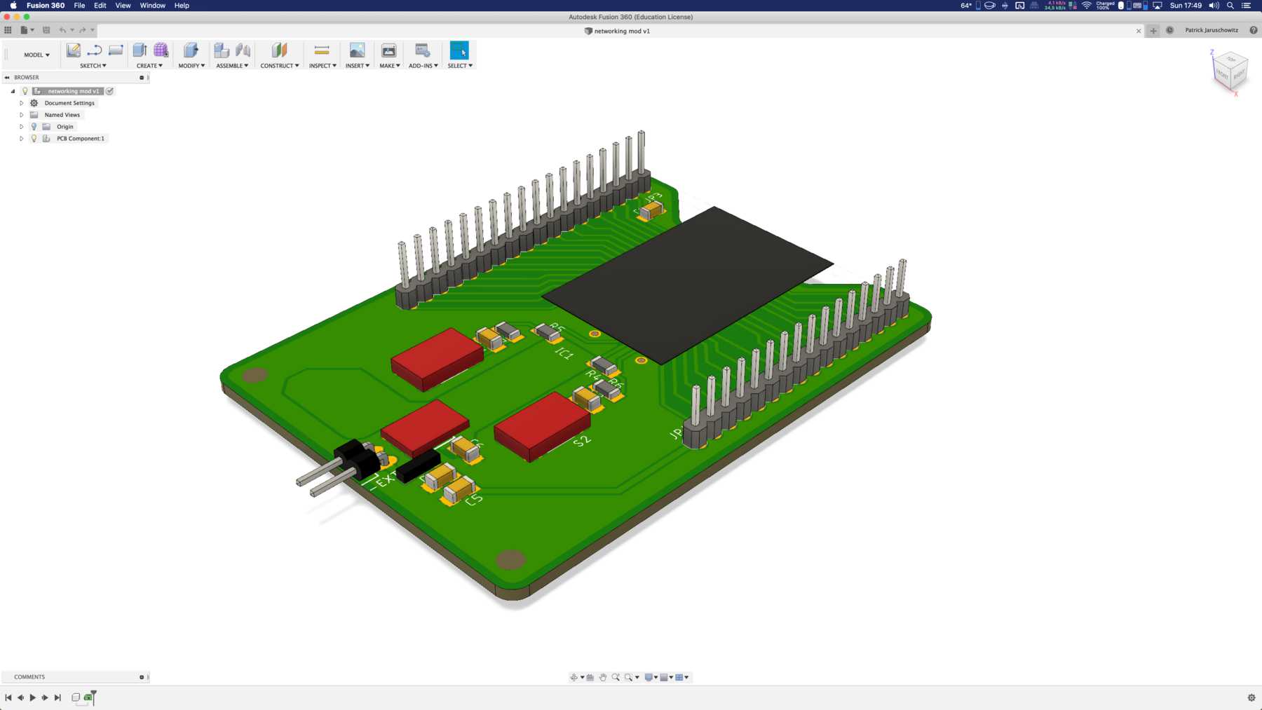
I wanted to render this picture. The following image is the result compared to the online preview of Fusion 360 in your browser at myhub-Autodesk.
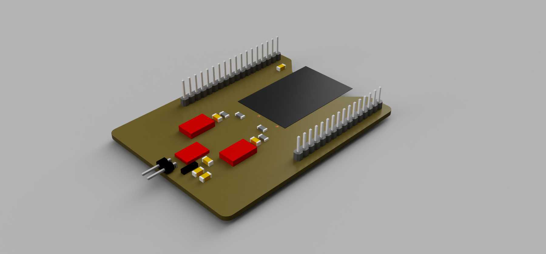
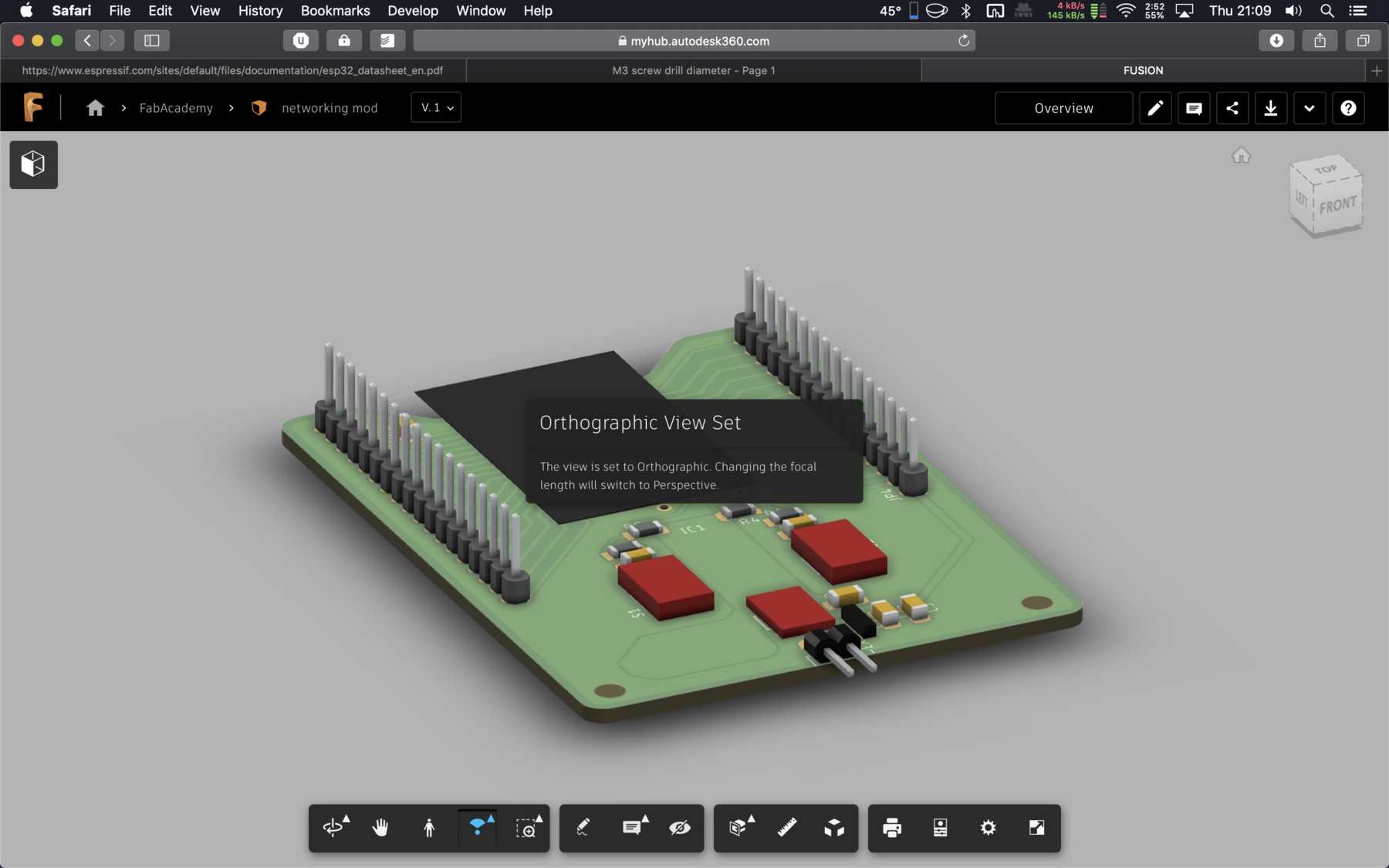
That’s a wonderful preview!
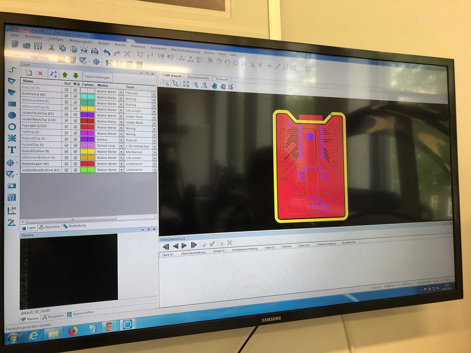
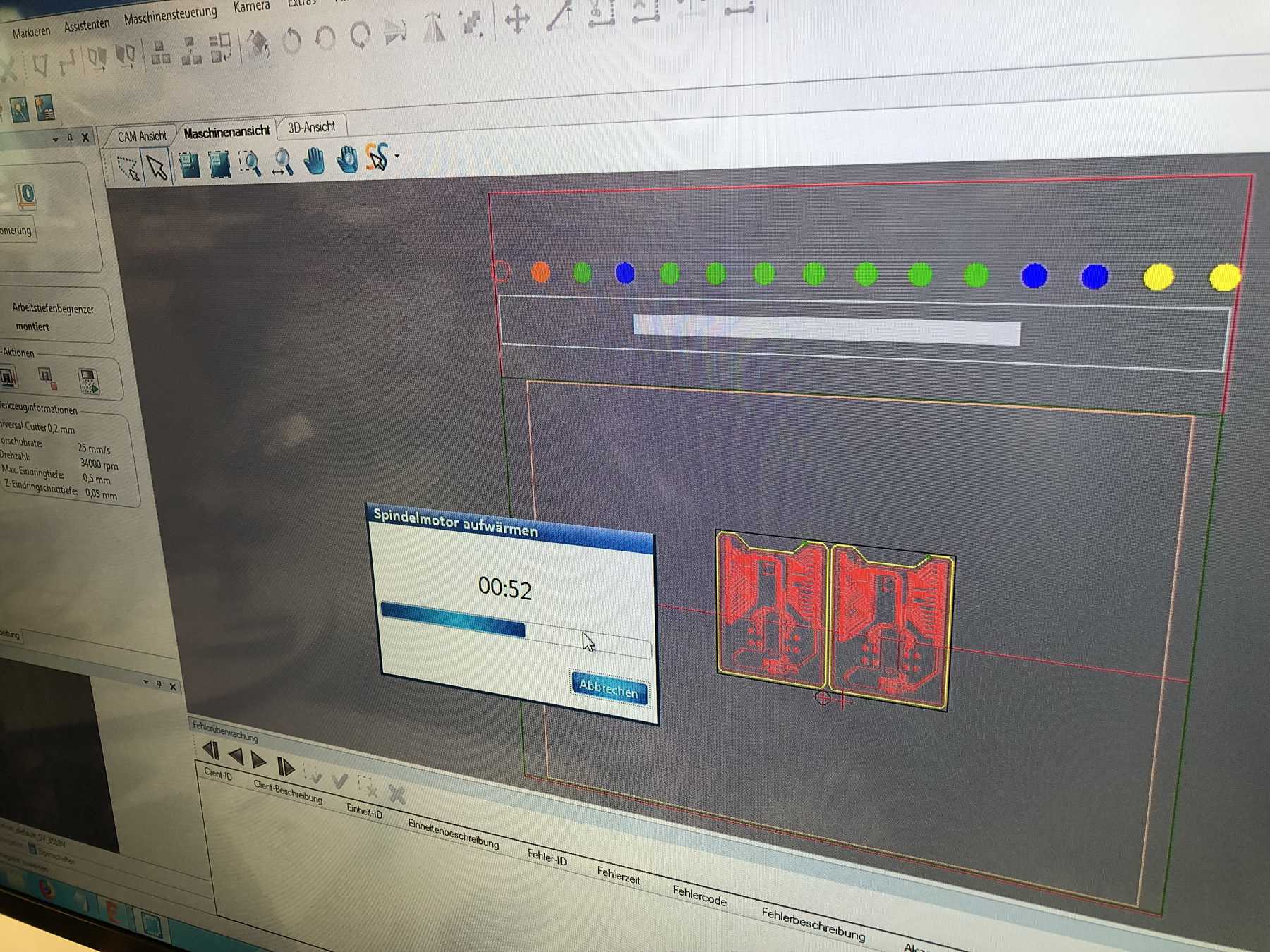
In the next step I was allowed to go to the milling machine again. Since I became a big fan of the LPKF ProtoMat S63, I made another video of the manufacturing process:
Here are two more pictures of the LPKF CircuitPro operating software during the milling process:
As always, the result was precise. I manually checked all paths under the stereomicroscope. No errors so far to recognize. Afterwards it was sprayed with solder varnish.
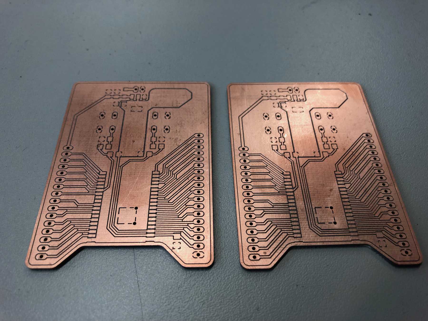
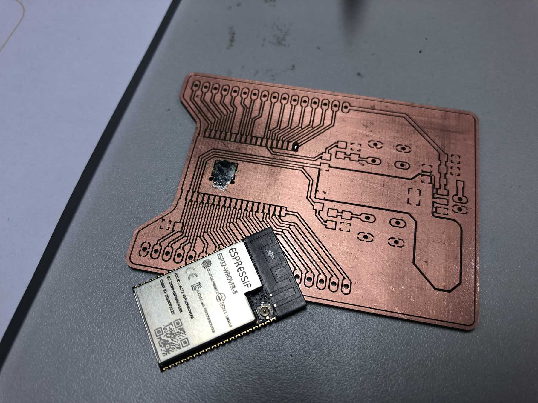
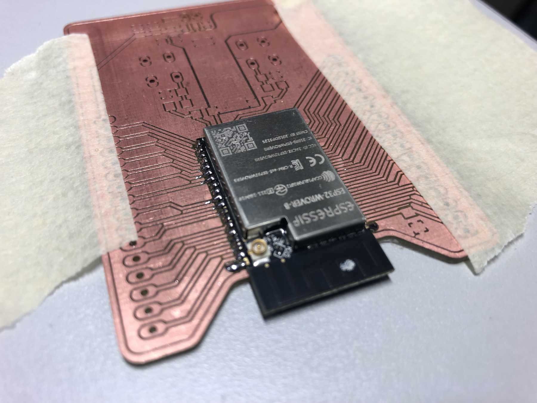
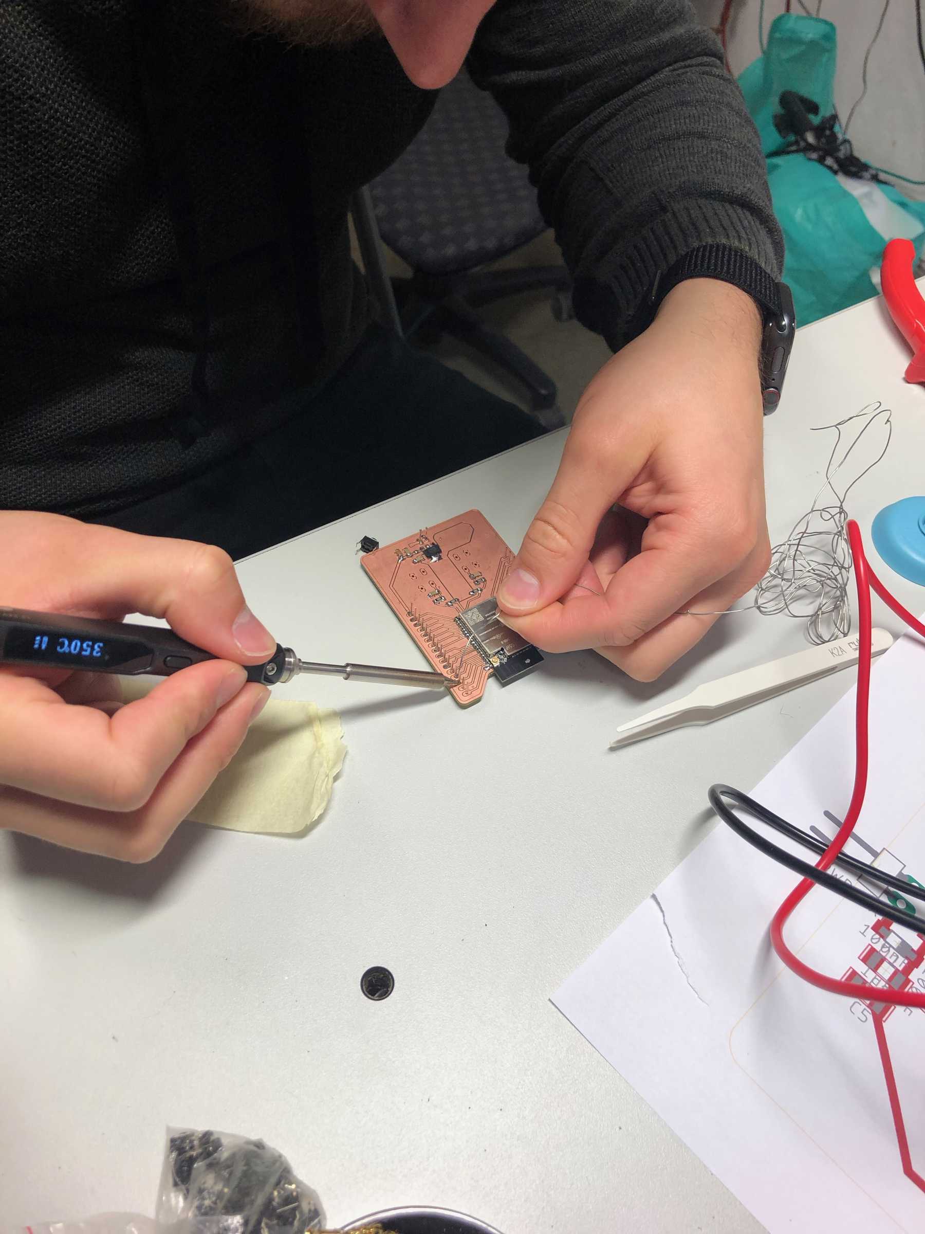
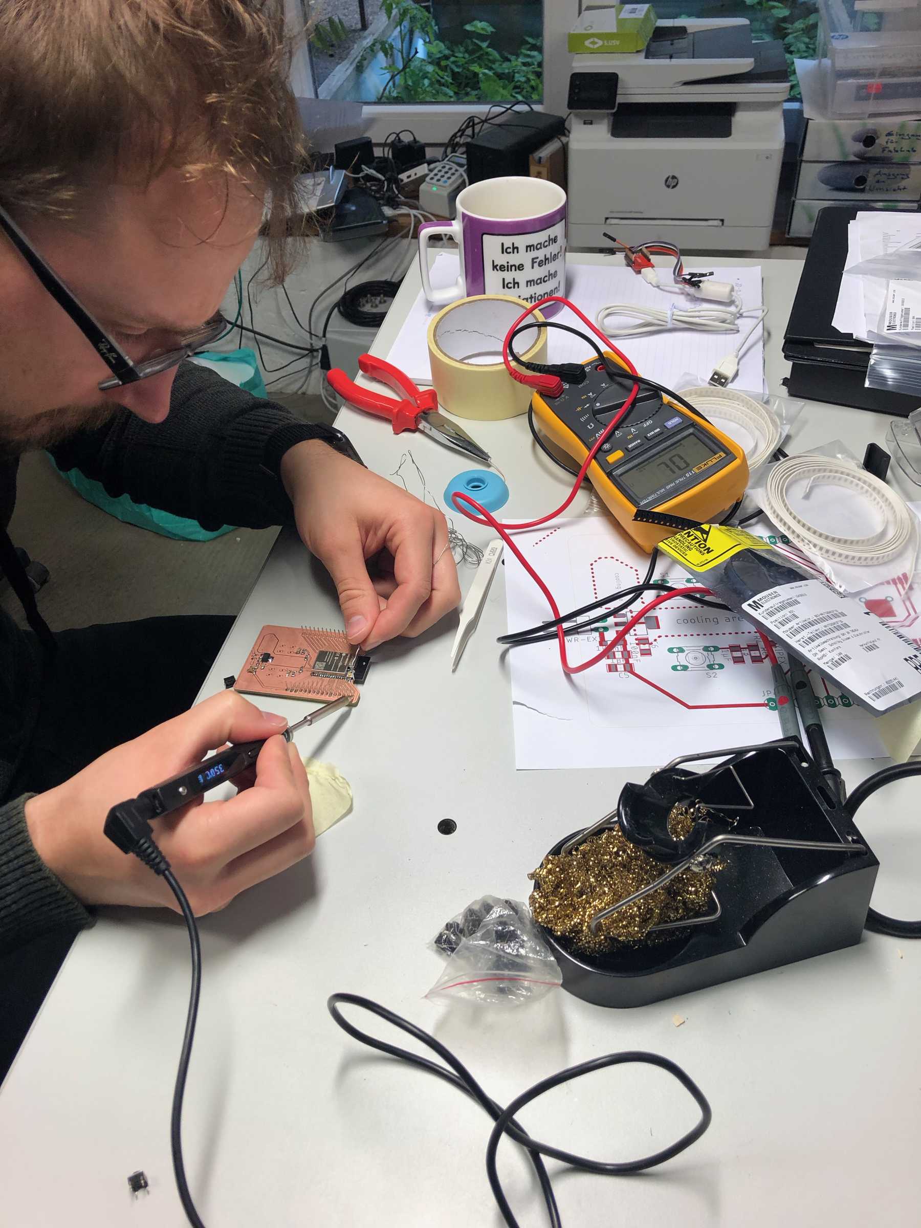
Now the assembly of the board with the above mentioned components began. Therefore I thought about two ways. The first was the manual soldering way. The second was to use the reflow oven. Both boards worked nevertheless very well and the manual soldering process was definitely more fun.
The fun could have lasted a little longer!
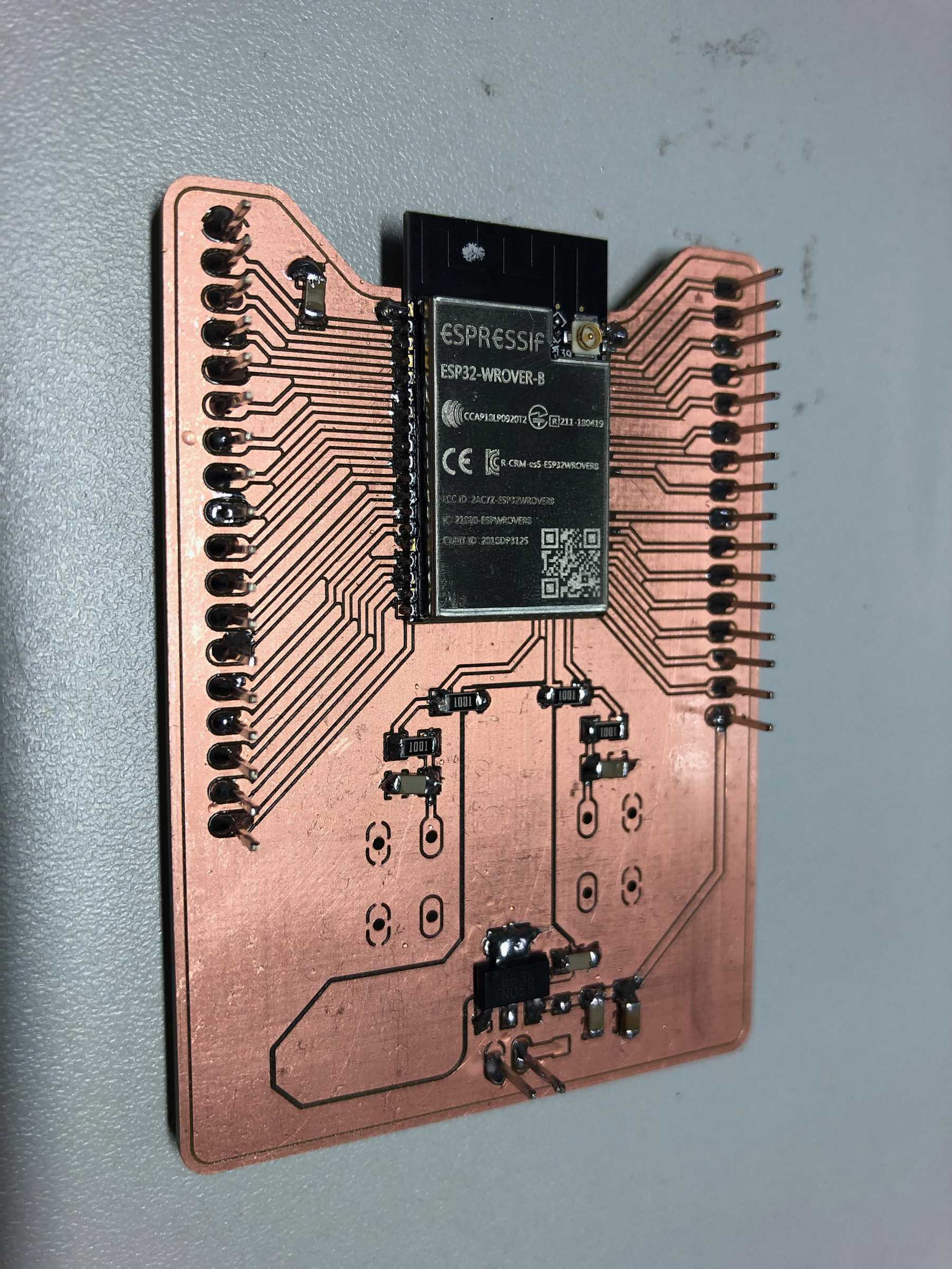
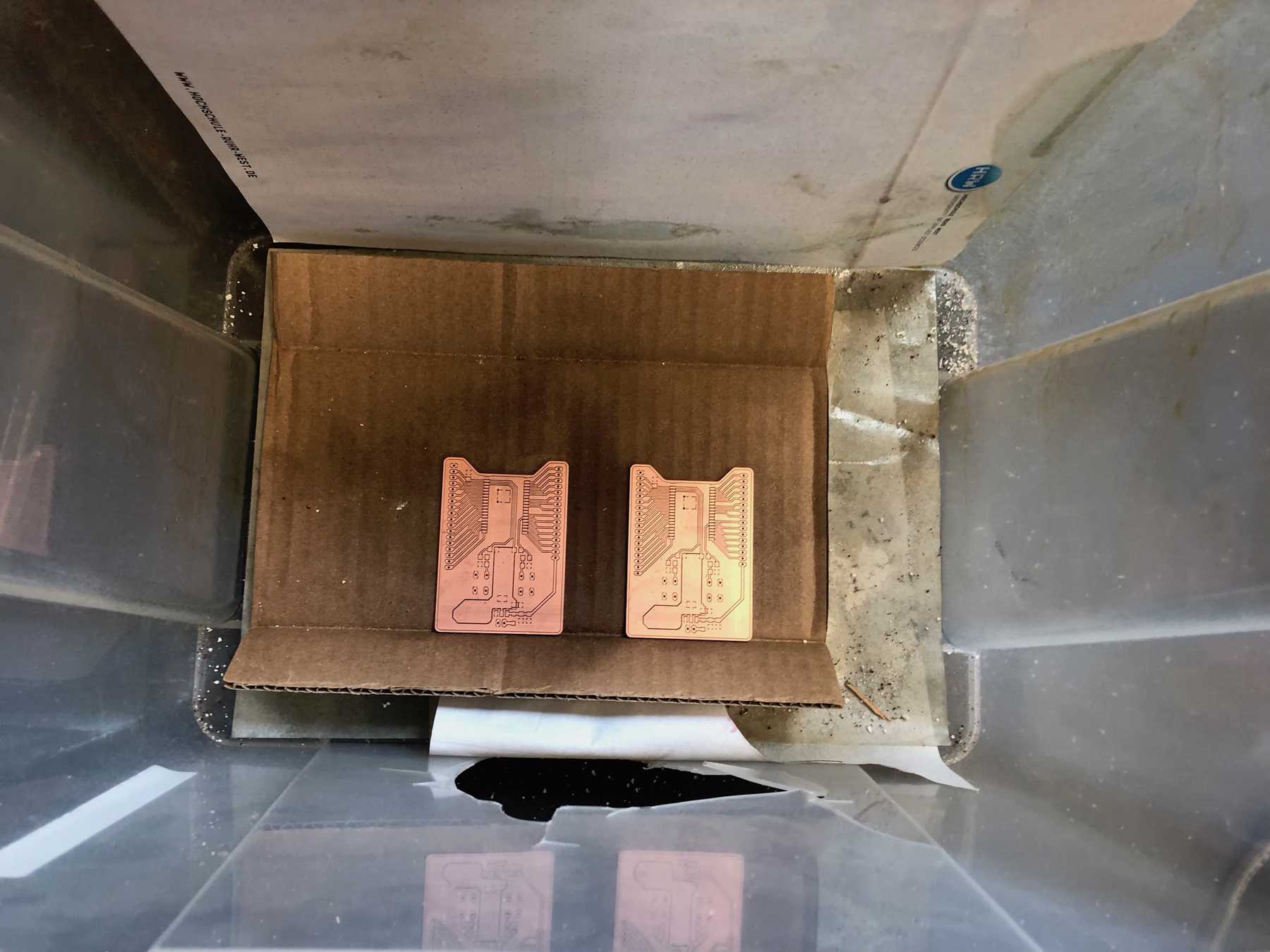
After the whole manufacturing process and the soldering process I was faced with the following result:
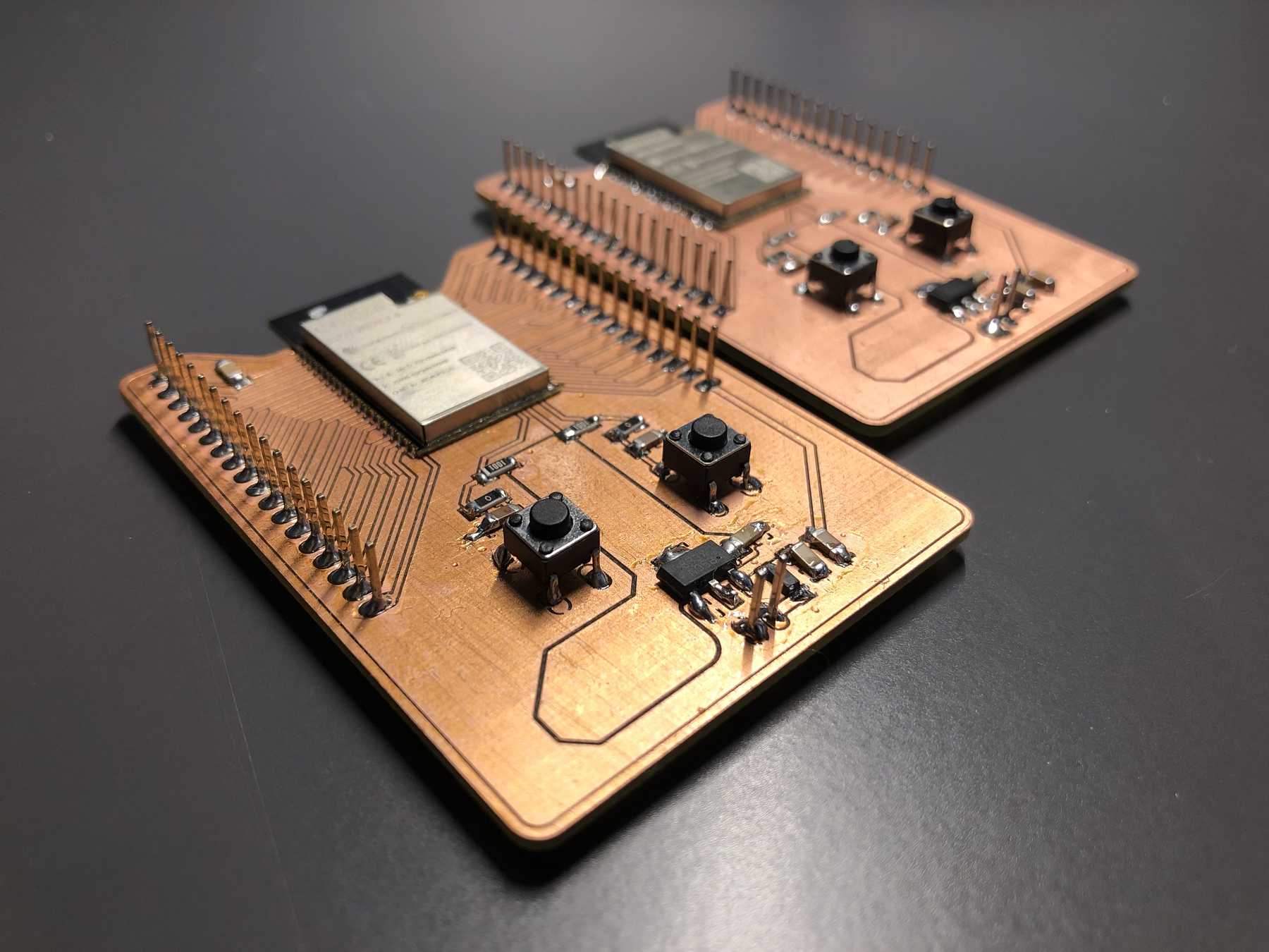
Now the question was: Do they work?
WiFiScan
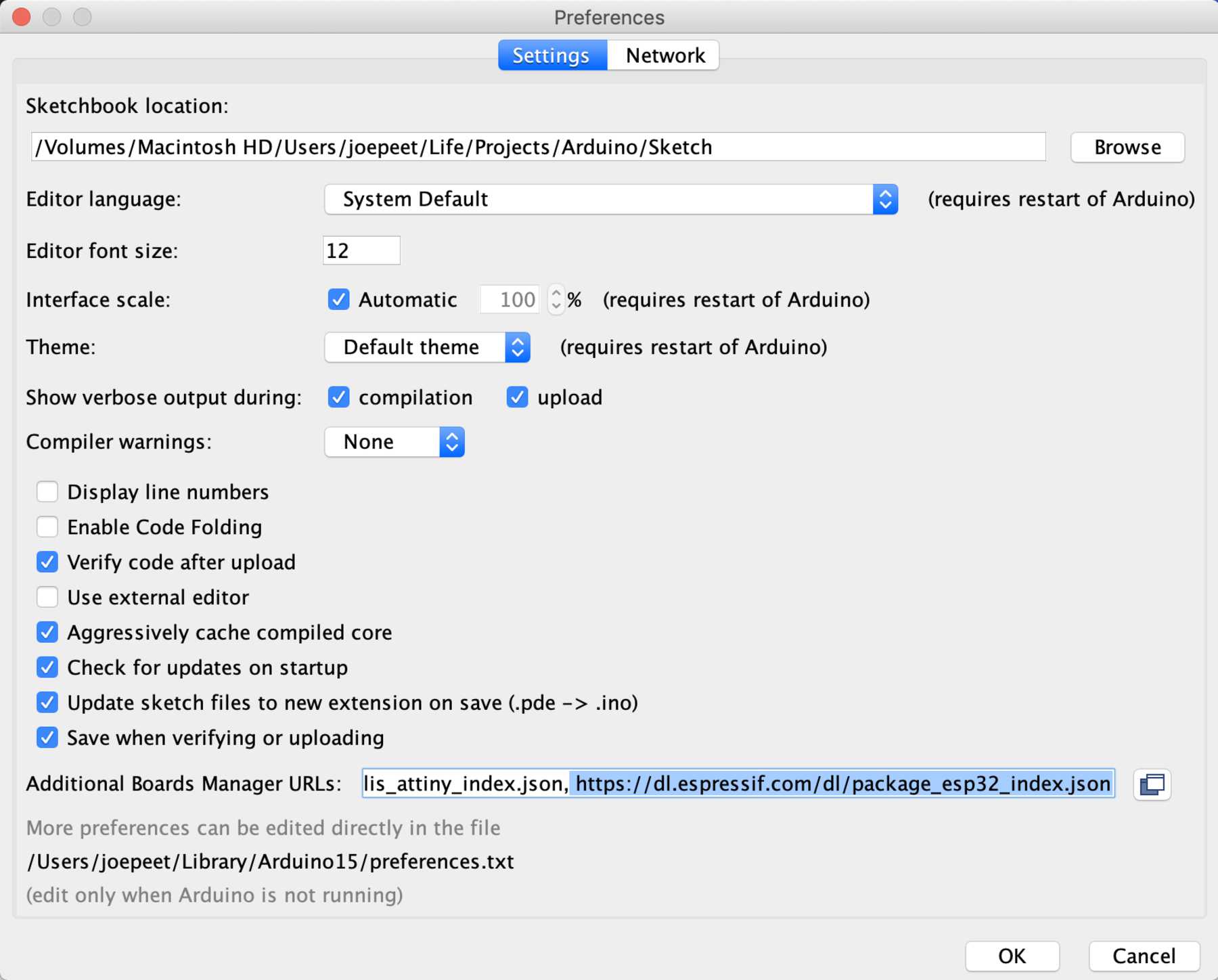
For Arduino I first had to download the support files for the ESP32 module. These can be installed via the board manager. Change to Arduino - Preferences - Additional Boards Manager URLs, enter the following URL https://dl.espressif.com/dl/package_esp32_index.json in the input field Further down as you can see on the picture field. Now you can select the boards in the board manager.
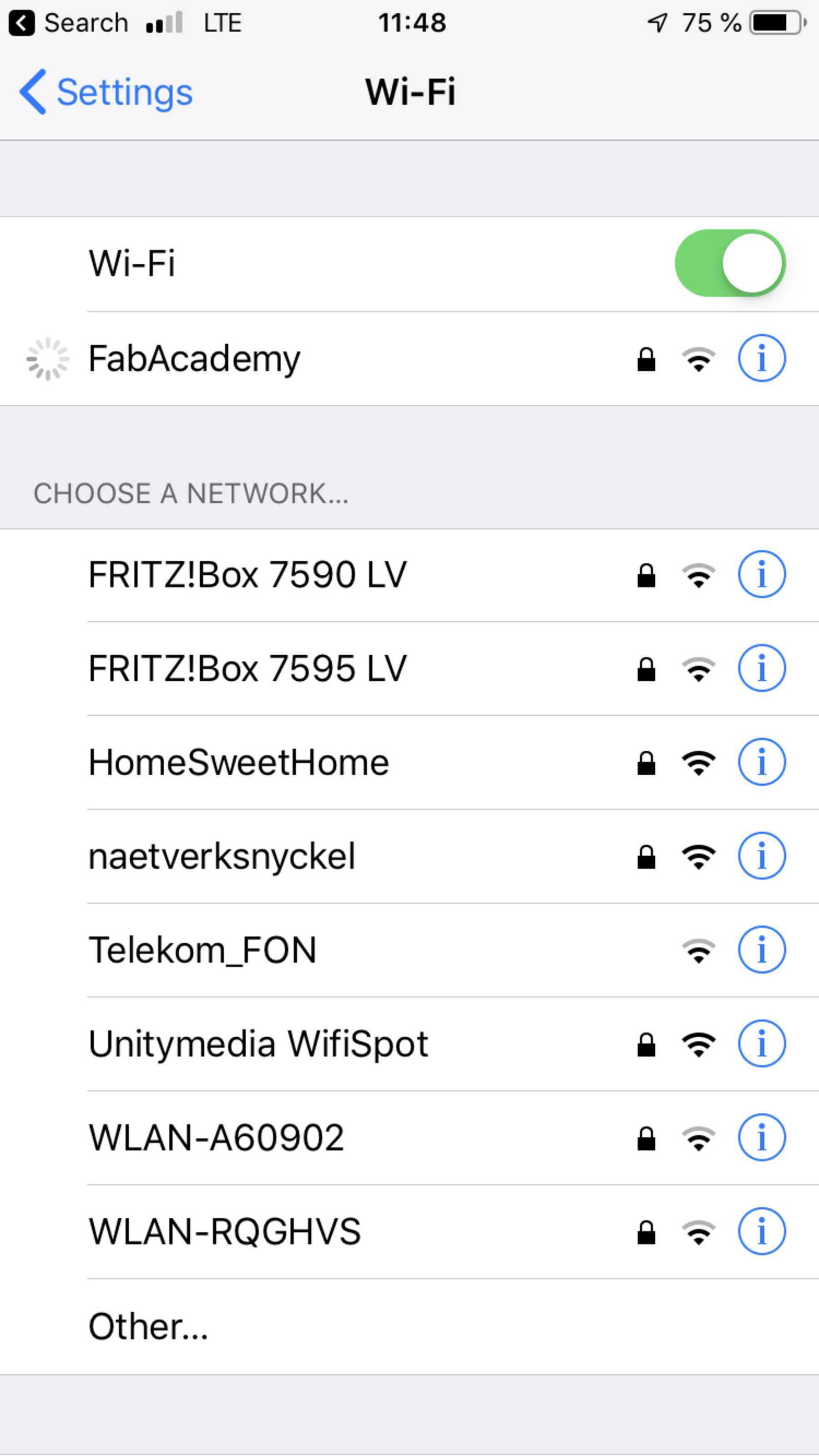
First I scanned the WLAN. The example-sketch can be found at File - Example - ESP32 - WiFiScan, so it looks like this:
LED-Test
The serial communication works. Now another LED test:
const int ledPin1 = 5;
const int ledPin2 = 21;

void setup() {
  pinMode(ledPin1, OUTPUT);
  pinMode(ledPin2, OUTPUT);
}

void loop() {
  digitalWrite(ledPin1, HIGH);
  digitalWrite(ledPin2, LOW);
  delay(1000);
  digitalWrite(ledPin1, LOW);
  digitalWrite(ledPin2, HIGH);
  delay(1000);
}
With the LED test the two LEDs are controlled via HIGH and LOW. Via GPIO pin 5 and 21 they change simultaneously between on and off mode. This serves as a basis for later tests.
WiFi-Blinking
The next step was to establish a network connection and install a web server on the ESP32. Thanks to the extensive libraries etc. this is now very easy. I found a good tutorial at Random Nerd Tutorials.
I left the LED pin layout as described before. I changed the sketch slightly based on Random Nerd Tutorials to fit the Fab Academy. The sketch looked like this at the end:
// Build on https://randomnerdtutorials.com/esp32-web-server-arduino-ide/
#include <WiFi.h>
#include <WebServer.h>

const char* ssid = "FabAcademy";
const char* password = "123";

/* Put IP Address details */
IPAddress local_ip(192,168,1,1);
IPAddress gateway(192,168,1,1);
IPAddress subnet(255,255,255,0);

WebServer server(80);

uint8_t LED1pin = 5;
bool LED1status = LOW;

uint8_t LED2pin = 21;
bool LED2status = LOW;

void setup() {
  Serial.begin(115200);
  pinMode(LED1pin, OUTPUT);
  pinMode(LED2pin, OUTPUT);

  WiFi.softAP(ssid, password);
  WiFi.softAPConfig(local_ip, gateway, subnet);
  delay(100);

  server.on("/", handle_OnConnect);
  server.on("/led1on", handle_led1on);
  server.on("/led1off", handle_led1off);
  server.on("/led2on", handle_led2on);
  server.on("/led2off", handle_led2off);
  server.onNotFound(handle_NotFound);

  server.begin();
  Serial.println("HTTP server started");
}

void loop() {
  server.handleClient();
  if(LED1status)
  {digitalWrite(LED1pin, HIGH);}
  else
  {digitalWrite(LED1pin, LOW);}

  if(LED2status)
  {digitalWrite(LED2pin, HIGH);}
  else
  {digitalWrite(LED2pin, LOW);}
}

void handle_OnConnect() {
  LED1status = LOW;
  LED2status = LOW;
  Serial.println("Status of LED Green: OFF | Status of LED Red: OFF");
  server.send(200, "text/html", SendHTML(LED1status,LED2status));
}

void handle_led1on() {
  LED1status = HIGH;
  Serial.println("Status of LED Green: ON");
  server.send(200, "text/html", SendHTML(true,LED2status));
}

void handle_led1off() {
  LED1status = LOW;
  Serial.println("Status of LED Green: OFF");
  server.send(200, "text/html", SendHTML(false,LED2status));
}

void handle_led2on() {
  LED2status = HIGH;
  Serial.println("Status of LED Red: ON");
  server.send(200, "text/html", SendHTML(LED1status,true));
}

void handle_led2off() {
  LED2status = LOW;
  Serial.println("Status of LED Red: OFF");
  server.send(200, "text/html", SendHTML(LED1status,false));
}

void handle_NotFound(){
  server.send(404, "text/plain", "Not found");
}

String SendHTML(uint8_t led1stat,uint8_t led2stat){
  String ptr = "<!DOCTYPE html> <html>\n";
  ptr +="<head><meta name=\"viewport\" content=\"width=device-width, initial-scale=1.0, user-scalable=no\">\n";
  ptr +="<title>Fab Academy NetworkingLED</title>\n";
  ptr +="<style>html { font-family: Helvetica; display: inline-block; margin: 0px auto; text-align: center;}\n";
  ptr +="body{margin-top: 50px;} h1 {color: #444444;margin: 50px auto 30px;} h3 {color: #444444;margin-bottom: 50px;}\n";
  ptr +=".button {display: block;width: 80px;background-color: #3498db;border: none;color: white;padding: 13px 30px;text-decoration: none;font-size: 25px;margin: 0px auto 35px;cursor: pointer;border-radius: 4px;}\n";
  ptr +=".button-on {background-color: #3498db;}\n";
  ptr +=".button-on:active {background-color: #2980b9;}\n";
  ptr +=".button-off {background-color: #34495e;}\n";
  ptr +=".button-off:active {background-color: #2c3e50;}\n";
  ptr +="p {font-size: 14px;color: #888;margin-bottom: 10px;}\n";
  ptr +="</style>\n";
  ptr +="</head>\n";
  ptr +="<body>\n";
  ptr +="<h1>Fab Academy Networking and Communications</h1>\n";
  ptr +="<h3>Week 14</h3>\n";

   if(led1stat)
  {ptr +="<p>LED Green Status: ON</p><a class=\"button button-off\" href=\"/led1off\">OFF</a>\n";}
  else
  {ptr +="<p>LED Green Status: OFF</p><a class=\"button button-on\" href=\"/led1on\">ON</a>\n";}

  if(led2stat)
  {ptr +="<p>LED Red Status: ON</p><a class=\"button button-off\" href=\"/led2off\">OFF</a>\n";}
  else
  {ptr +="<p>LED Red Status: OFF</p><a class=\"button button-on\" href=\"/led2on\">ON</a>\n";}

  ptr +="</body>\n";
  ptr +="</html>\n";
  return ptr;
}
This sketch has several functions. First the server is started and the various parameters such as IP, WLAN name, serial connection, etc. are created. In the loop there is always the status of the LED, which is queried. Depending on the variables, the website builds up again and again and adapts itself accordingly. The result can be seen here:
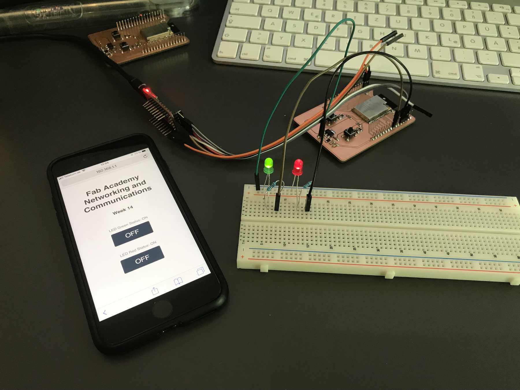
Afterwards a proof video that the whole thing worked and could be connected via Wlan!
Group assignment
I2C
In the group assignment I should let two devices communicate with each other. Unfortunately, I had no other project at that time that could communicate with me. I tried WLAN in advance. Now it would be nice to try something classic: Maybe I²C? I²C is a serial data bus that was developed by Philips Semiconductors and is mainly used for internal device communication. So, two Arduino boards (ESP32 still has some difficulties), two LEDs and as always a little blinking.
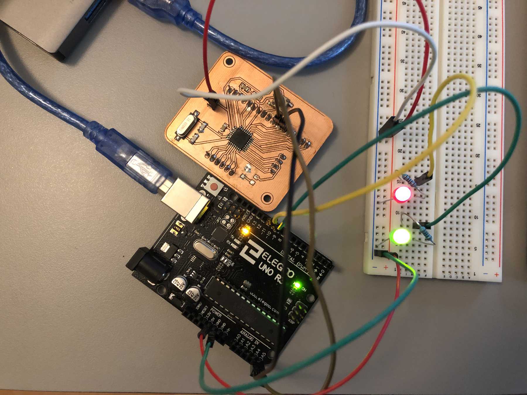
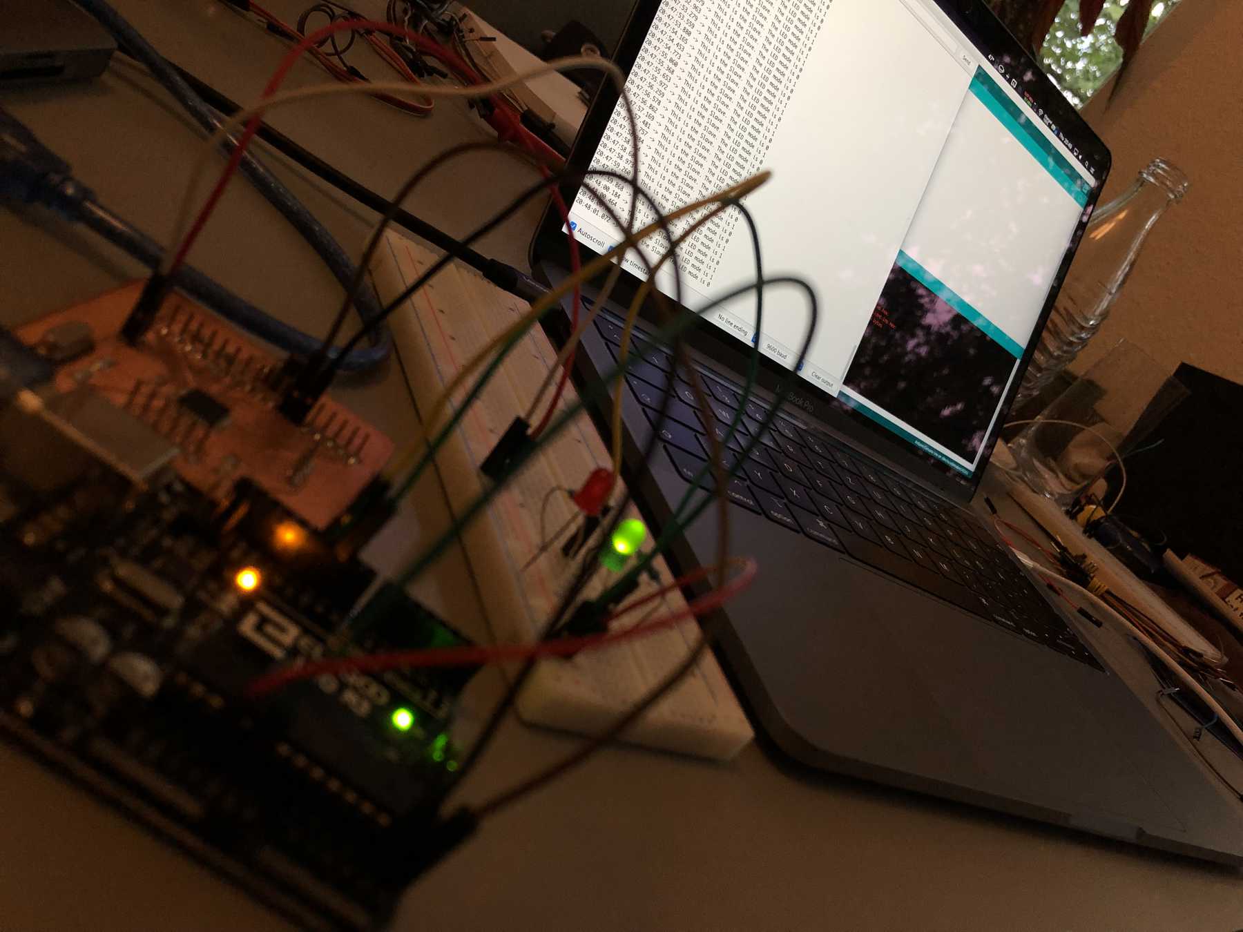
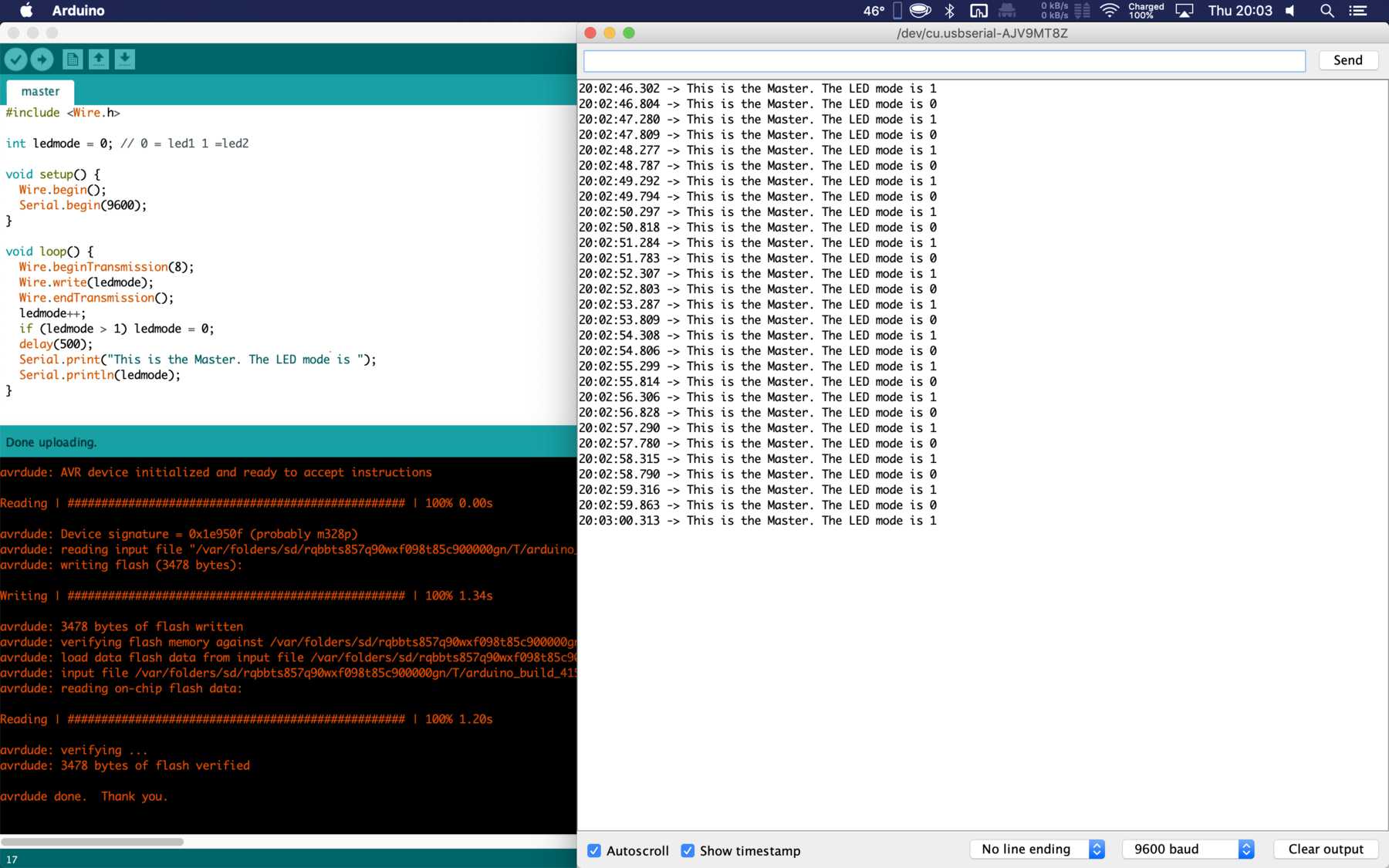
Now it was about connecting these two boards with each other. For this I looked at one or two tutorials and compared them. I found a simple tutorial at Instructables, which was one from cornelam. I oriented myself to it and analyzed the lines bit by bit and wrote my own code. The code for the master was relatively simple. The master was sending either the value 0 or 1 via the wire protocol in 300ms intervals. The slave reads the value and acts differently depending on the numerical value. In this case either one LED or two LEDs flash.
// Master
// Built on https://www.instructables.com/id/I2C-between-Arduinos/
#include <Wire.h>

int ledmode = 0; // 0 = led1 1 =led2

void setup() {
  Wire.begin();
  Serial.begin(9600);
}

void loop() {
  Wire.beginTransmission(8);
  Wire.write(ledmode);
  Wire.endTransmission();
  ledmode++;
  if (ledmode > 1) ledmode = 0;
  delay(500);
  Serial.print("This is the Master. The LED mode is ");
  Serial.println(ledmode);
}
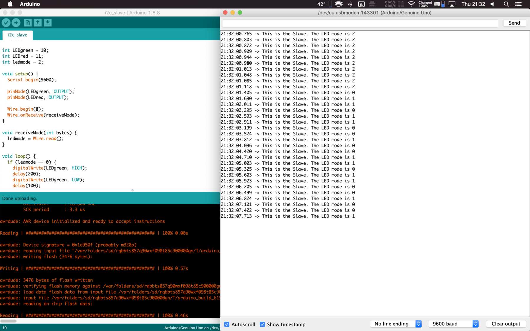
// Slave
// Built on https://www.instructables.com/id/I2C-between-Arduinos/
#include <Wire.h>

int LEDgreen = 10;
int LEDred = 11;
int ledmode = 2;

void setup() {
  Serial.begin(9600);

  pinMode(LEDgreen, OUTPUT);
  pinMode(LEDred, OUTPUT);

  Wire.begin(8);
  Wire.onReceive(receiveMode);
}

void receiveMode(int bytes) {
  ledmode = Wire.read();
}

void loop() {
  if (ledmode == 0) {
    digitalWrite(LEDgreen, HIGH);
    delay(200);
    digitalWrite(LEDgreen, LOW);
    delay(100);
  }
  if (ledmode == 1) {
    digitalWrite(LEDgreen, HIGH);
    digitalWrite(LEDred, HIGH);
    delay(200);
    digitalWrite(LEDgreen, LOW);
    digitalWrite(LEDred, LOW);
    delay(100);
  }
  Serial.print("This is the Slave. The LED mode is ");
  Serial.println(ledmode);
}
The whole thing looked like this on the serial monitor:
And last but not least a short proof video:
Here you can download the files mentioned above:
EAGLE files of the ESP32-board