Computer Controlled Cutting
Week 04
In the fourth week, we had to do the first group assignment. The task was to characterize the used laser cutter and to make test part(s) with various cutting settings and dimensions. In the individual assignment, I had to create something with the vinyl cutter and to design, laser-cut and document a parametric press-fit construction kit. It was one condition that the press-fit construction kit should be assembled in multiple ways.
Group assignment
Characterize the used lasercutter
For the group task, I first took a closer look at the laser which I use. The laser cutter is an indispensable tool in a FabLab and belongs to the standard equipment. Lasers are firmly integrated into our everyday lives through various consumer products such as printers, computer mice, barcode scanners and optical drives. They are also commonly used in industry, science, material processing, control technology, measurement technology, data technology, military technology, and medicine. The history of the laser is based on an extensive story. Albert Einstein published the theoretical concept of light propagation by stimulated emission of radiation in 1916. With this theoretical thought experiments, Einstein laid the foundation for the development of the laser. However, the precursor of the laser was an amplifier based on microwave radiation which was described in a publication in 1954. This so-called Maser (Microwave Amplification by Stimulated Emission of Radiation) consisted of a 2-energy level system which could not generate continuous microwave radiation. The difficulty was that no population inversion could be achieved to generate stimulated emission. The excited atoms/molecules fell back to the ground state. Basov, Prokhorov, and Townes were awarded with the Nobel Prize in Physics in 1964 for the concept of the maser.
How does a laser work?
Physically the laser consists of a pump source and an atomic or molecular amplification medium located in an optical resonator. The entire system works like an oscillator, which contains positive feedback in addition to amplification. The active laser material, either solid, liquid or gas, is passed several times by photons. The feedback is caused by the resonator structure consisting of at least two mirrors. The photon number increases exponentially due to the stimulated emission in the resonator. At the stimulated emission of radiation, a photon hits an excited level and generates thereby a resonant transition to a lower level. As a result, it emits a second photon with the energy hν, which is identical to the incoming photon in all its properties. The principle of the laser is only functional if the simulated emission of excited atoms of the active laser material is greater than the sum of resonator loss and spontaneous emission.
Material test with the laser cutter
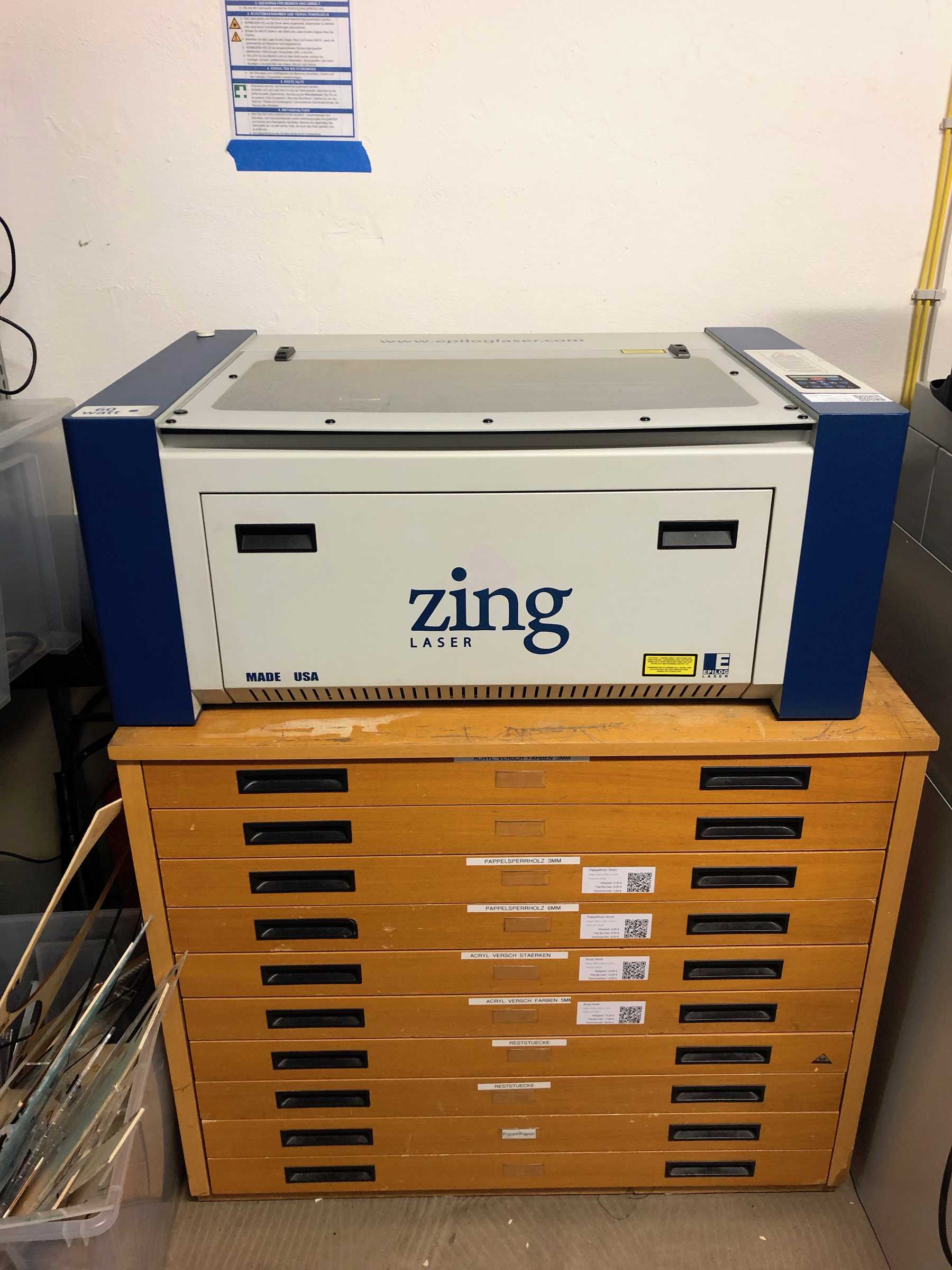
For my test I wanted to create different test cards for our FabLab. These are used to show the guests what is possible with the laser cutter, how big the influence of the parameters and how relevant the interaction between material and laser is. The laser cutter I used is the Epilog Zing 24 with 60 Watt. It is based on a CO2-laser which produces a beam of infrared light with a wavelength of 10.2 micrometers. The useable area is 600 x 300 mm.
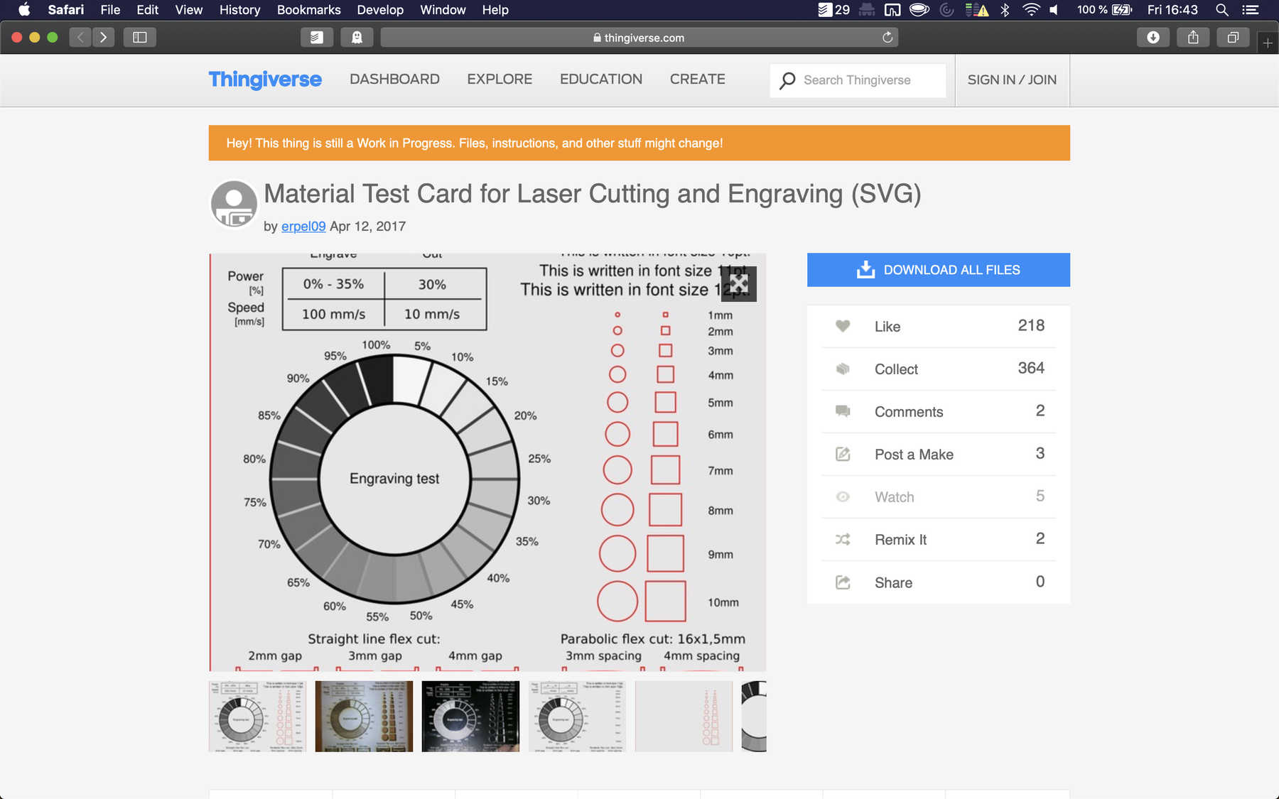
I have already searched for interesting templates once before the Fab Academy, which are able to present the different laser settings to our guests in the FabLab in a simple way. I quickly found what I was looking for and decided in favour of the template named Material Test Card for Laser Cutting and Engraving (SVG) on Thingiverse. After downloading the file I changed the template in many ways to use it with different materials. Since the software of the Epilog Zing 24, unfortunately, does not support Mac there is, fortunately, an excellent software called VisiCut. The software is open-source, free and supports SVG, EPS, DXF and the own VisiCut file format PLF. VisiCut was created in a bachelor thesis project by Thomas Oster, who was supervised by René Bohne. There are further extensions for the Epilog Zing laser cutter, for example a webcam module, which is very interesting.
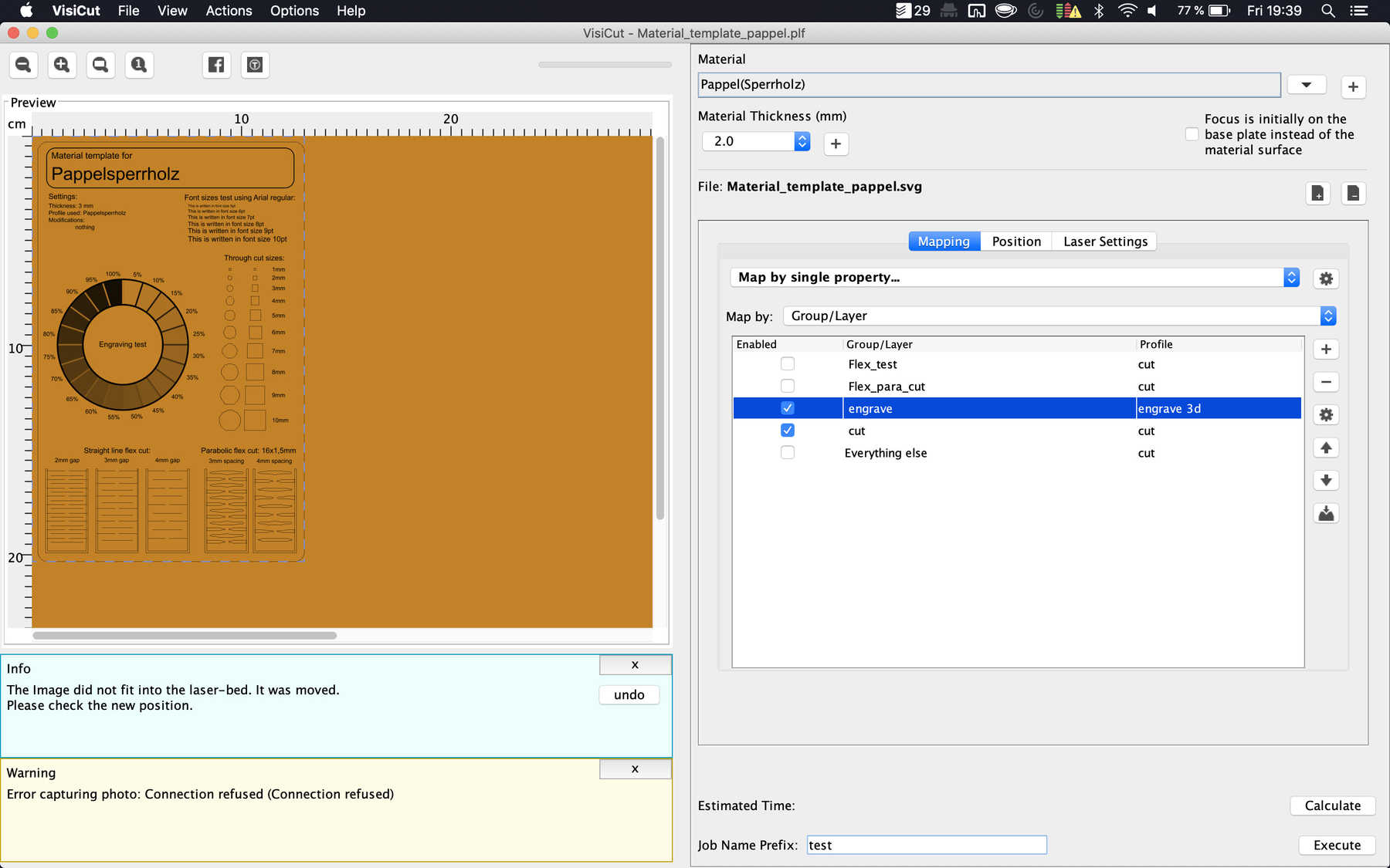
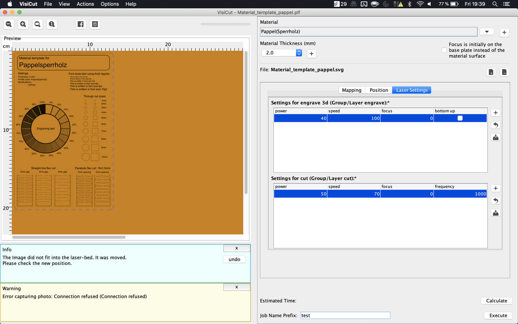
If you look at these test cards, you have to keep in mind that the setting is always the percentage of the current setting. This means that if I talk about 30% on the template, it’s 30% of the set performance. To select the correct template you have to check two different settings. First: Select the area which should be cut, second: Select the area which should be engraved. For engraving, you have to choose the mode to engrave 3D. As you can see in the video the partial areas arranged in a circle are engraved with different grades of power.
Results
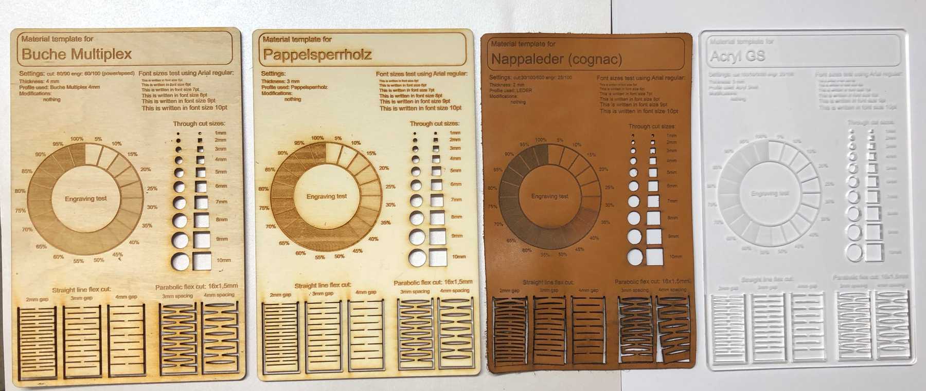
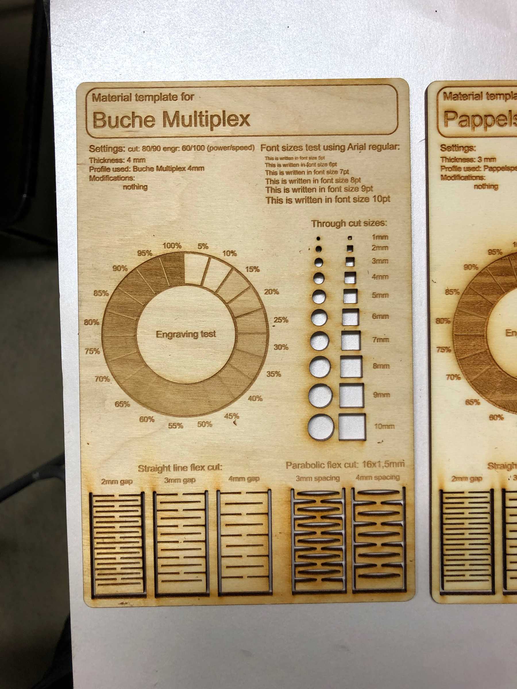
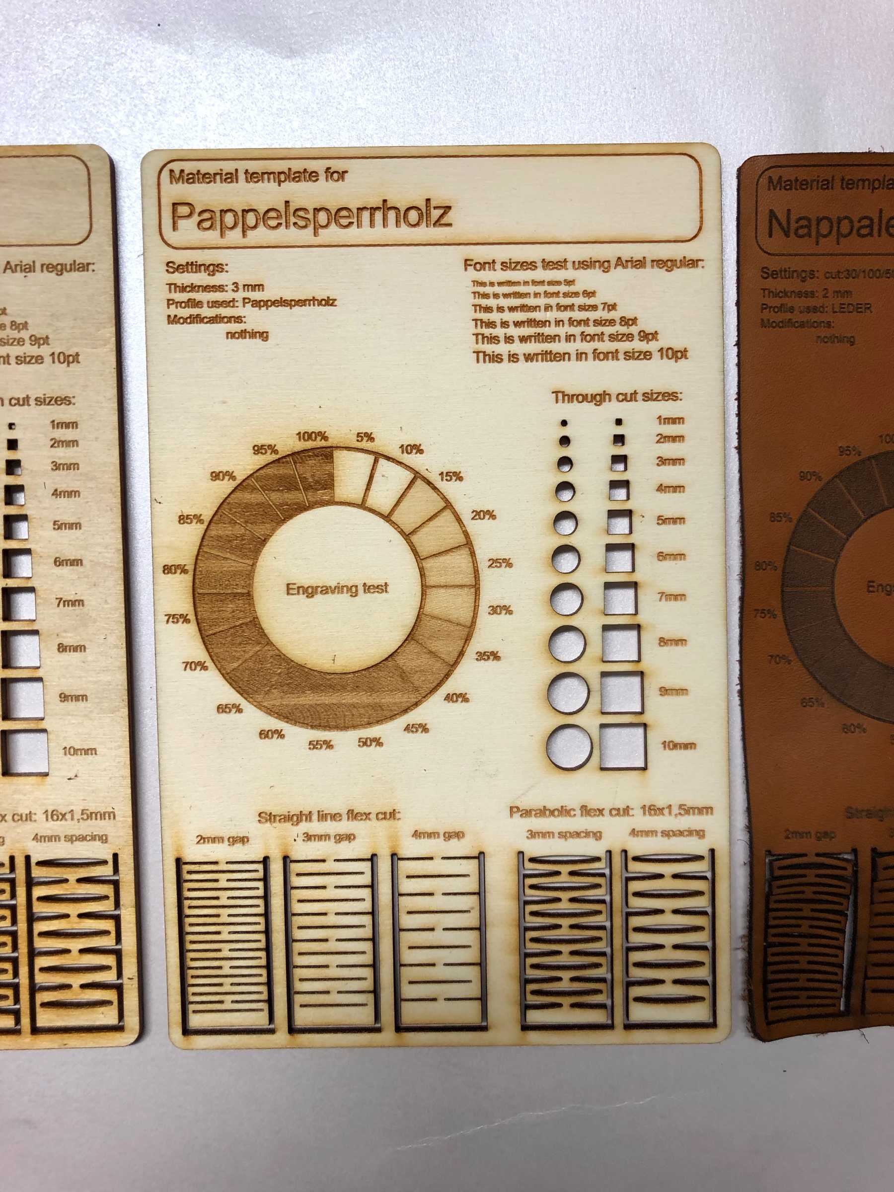
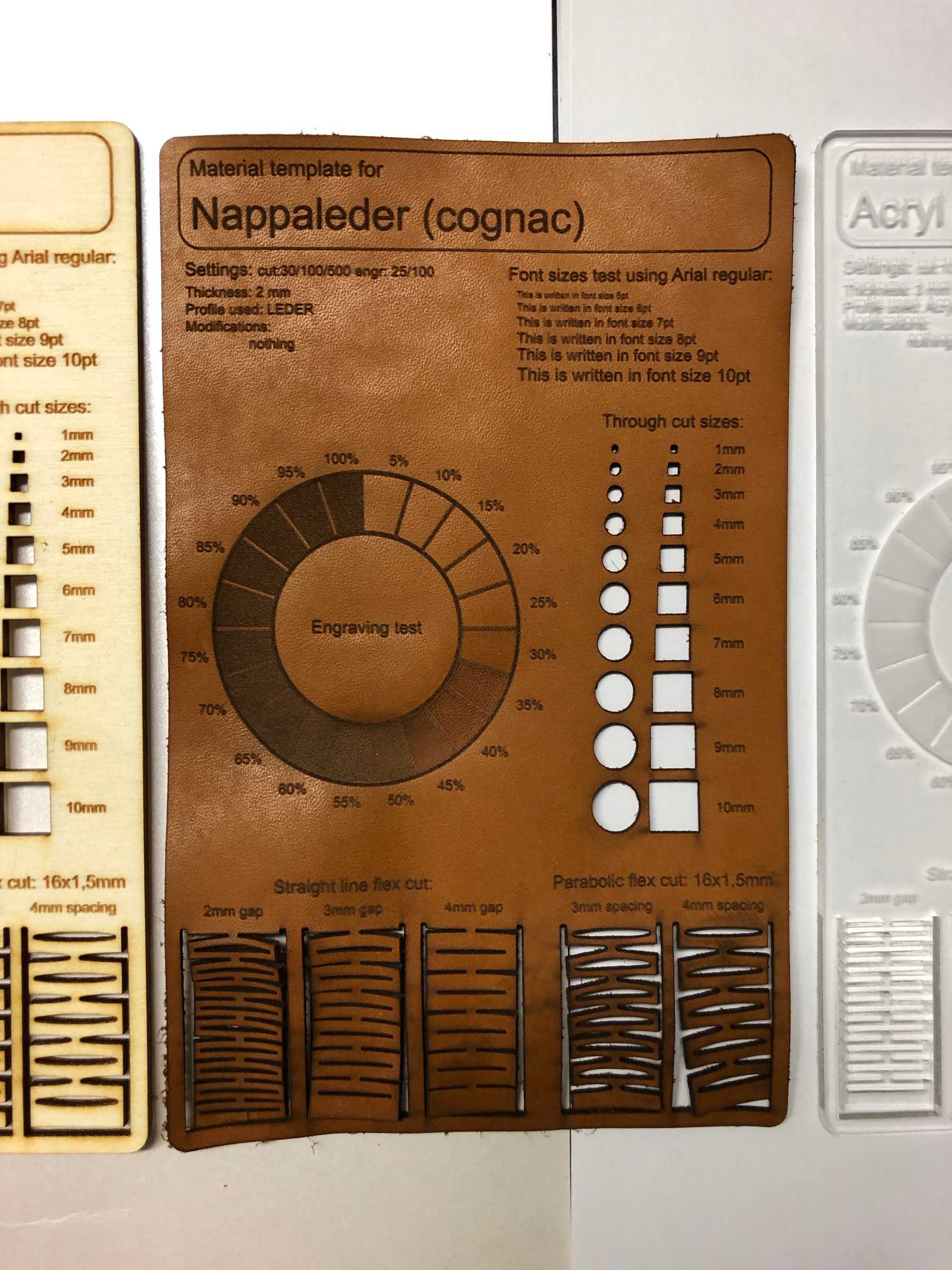
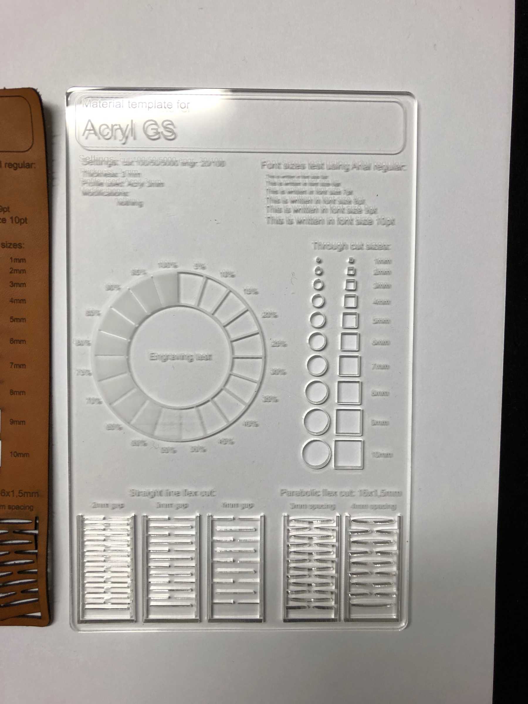
The results show clearly that I had to produce even more test cards. Nevertheless, it is very nice to show the guests of our FabLab how important it is to find the correct laser settings and to optimize them. In total, I created four test cards. Two types of wood, one of acrylic, and one of leather. Finally, these test cards illustrate very plainly to what extent the settings of the laser power can be optimized to get the desired results.
Individual assignment
Designing a parametric press-fit construction kit
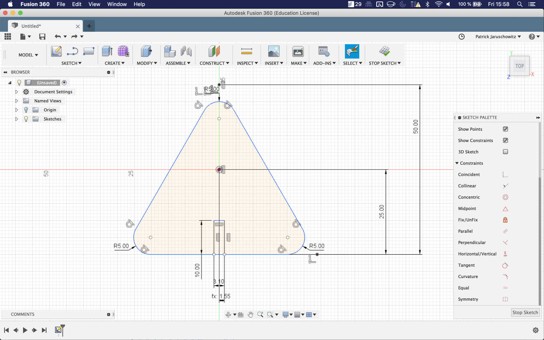
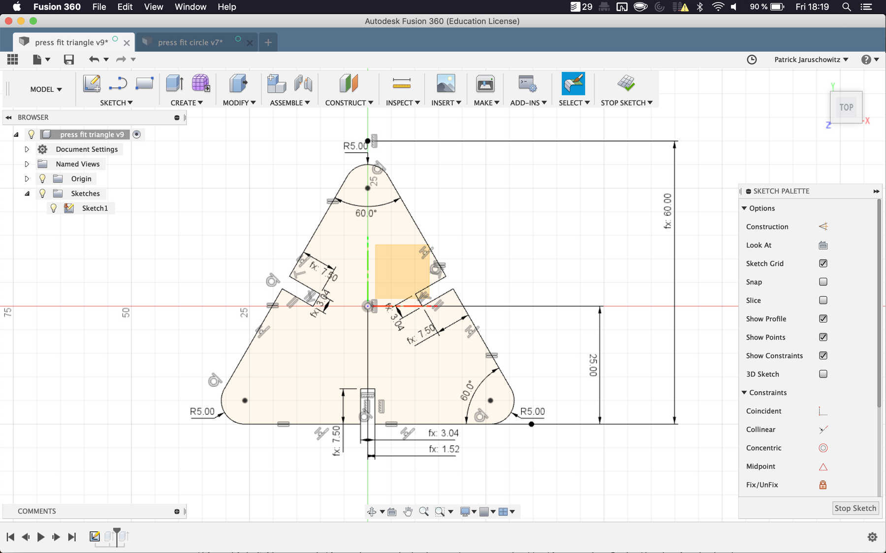
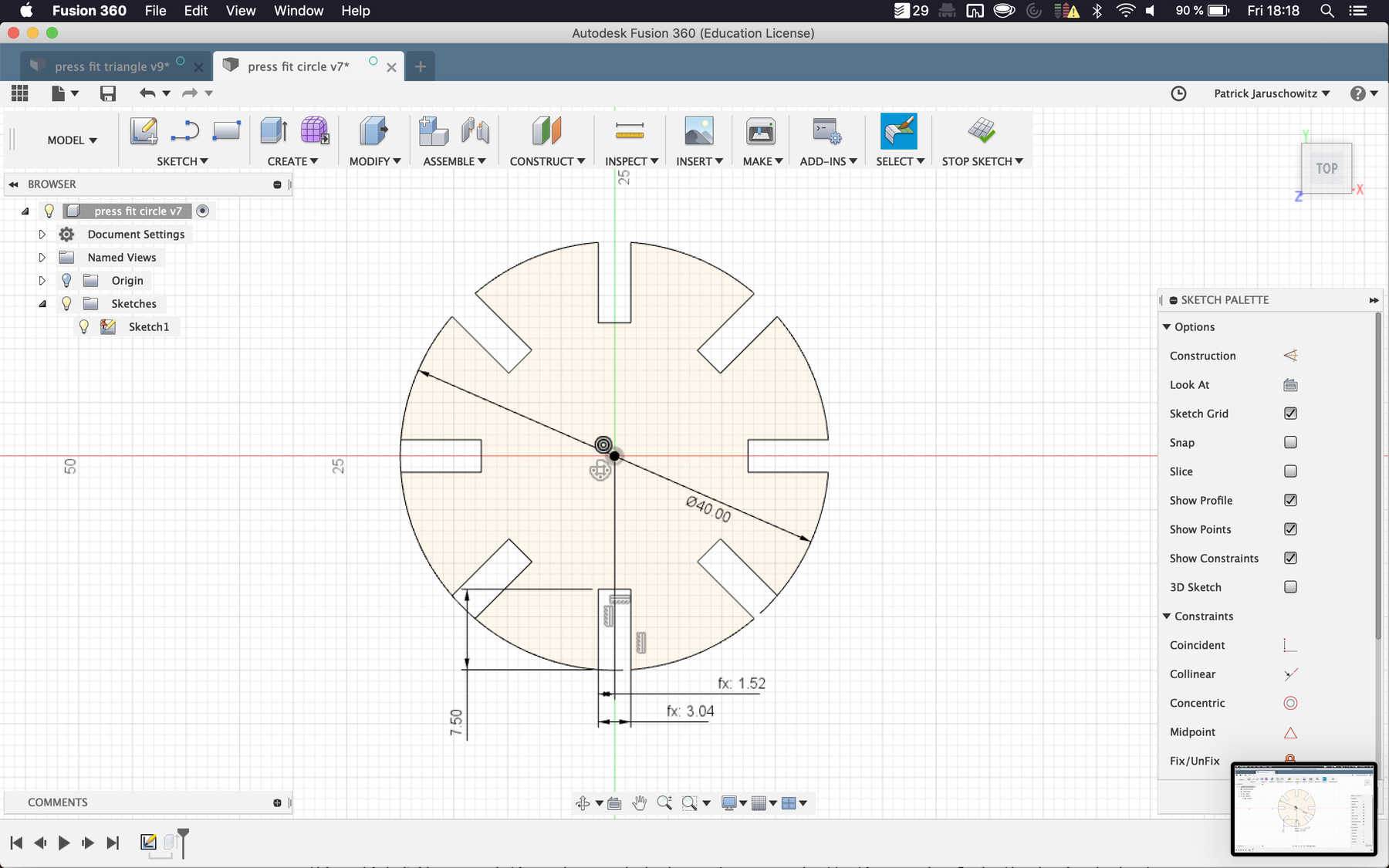
For the design, I first made a sketch by hand and got inspired by previous projects in the Fab Academy. It became clear to me that a simple but at the same time constructive parametric design has a lot of potentials. The design should consist of two components, each with at least one variable for the total height. I used the CO2 laser cutter Epilog Zing 24 characterized above. Instead of the recommended material cardboard, I used poplar wood, which looks more beautiful for the later use.
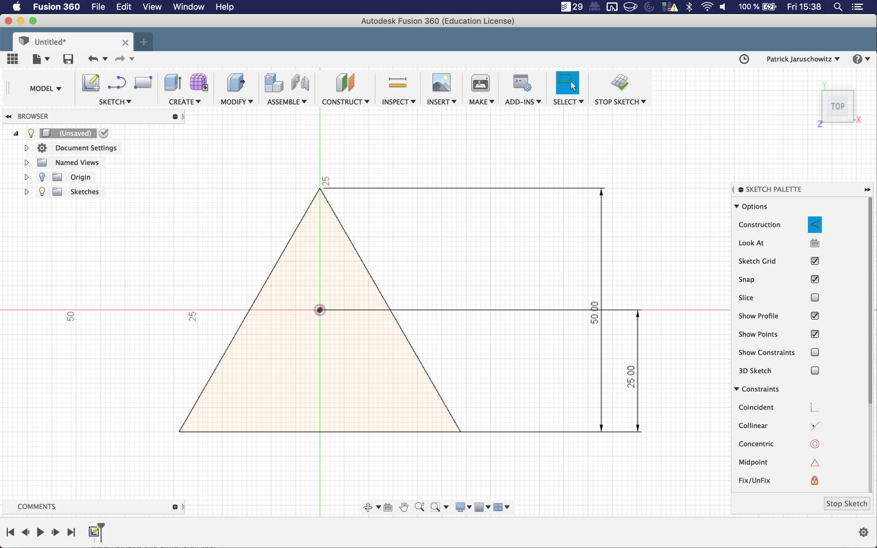
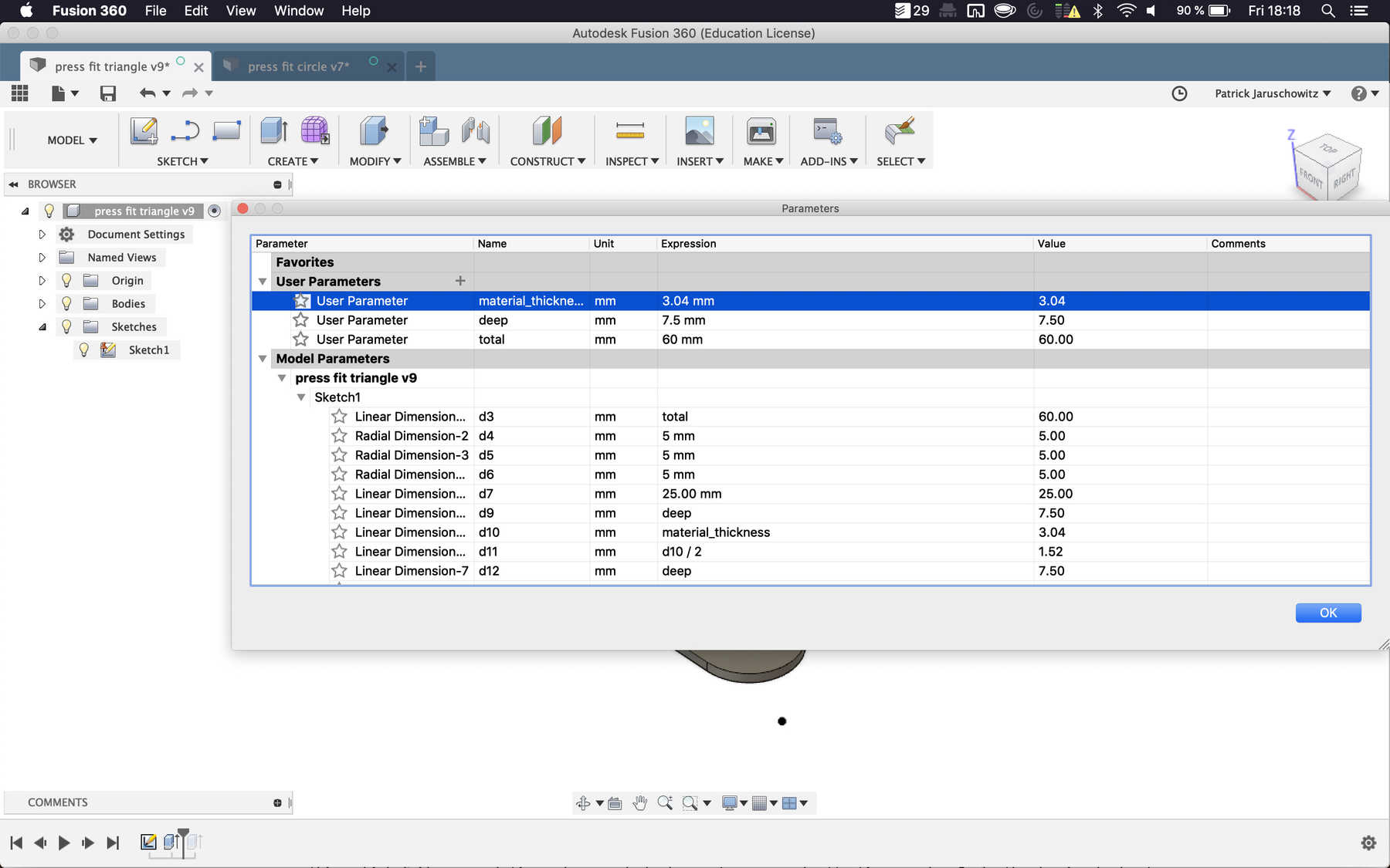
On the pictures you can see that I integrated many restrictions into the technical drawing. This ensured that parametric changes did not change the original design. The options for parameters can be found under Modifiy - Change Parameters.
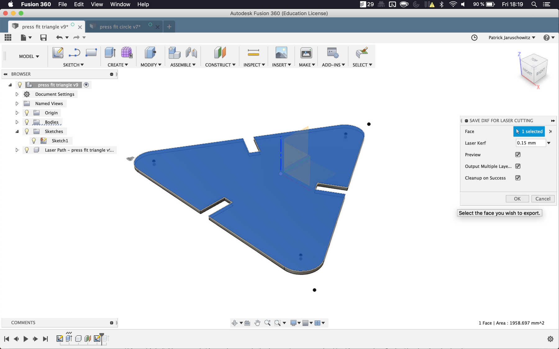
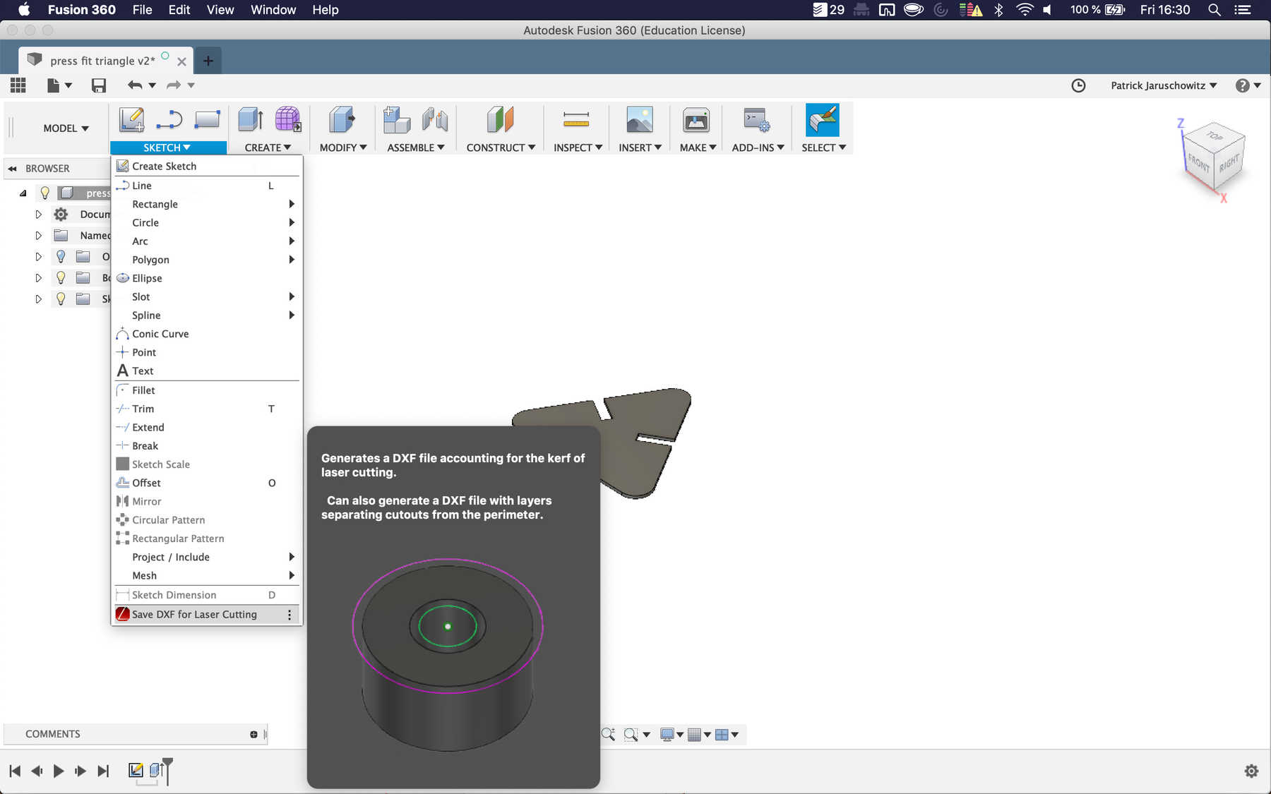
In the next step, I wanted to export the technical drawings. There are two ways to do this. The first one is to make a right-click on the sketch in Fusion 360 and then choose the option export. The alternative way is to use the plug-in DXF for Laser. This allows you to select multiple layers and then export them together as one DXF file.
Using Adobe Illustrator
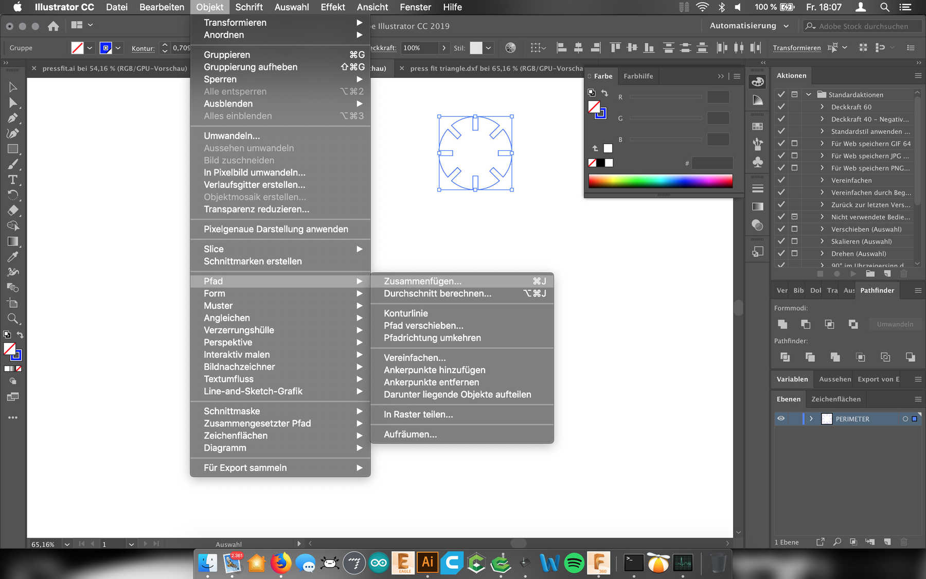
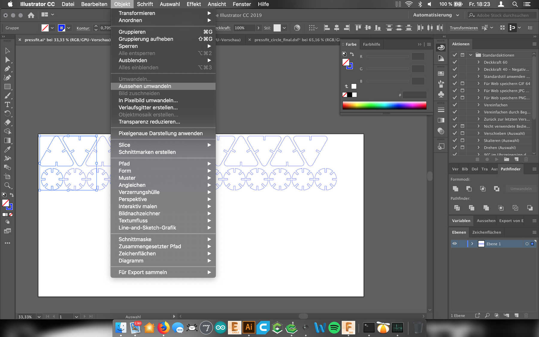
In order to quickly distribute these models over an area of 600 x 300 mm, I prefer to use Adobe Illustrator as a vector program. Here you can fill the area with a few mouse clicks. Only a few important steps are necessary: After importing the DXF file, the lines have to be merged. How this works you can see on the following picture: Object > Path > Combine.
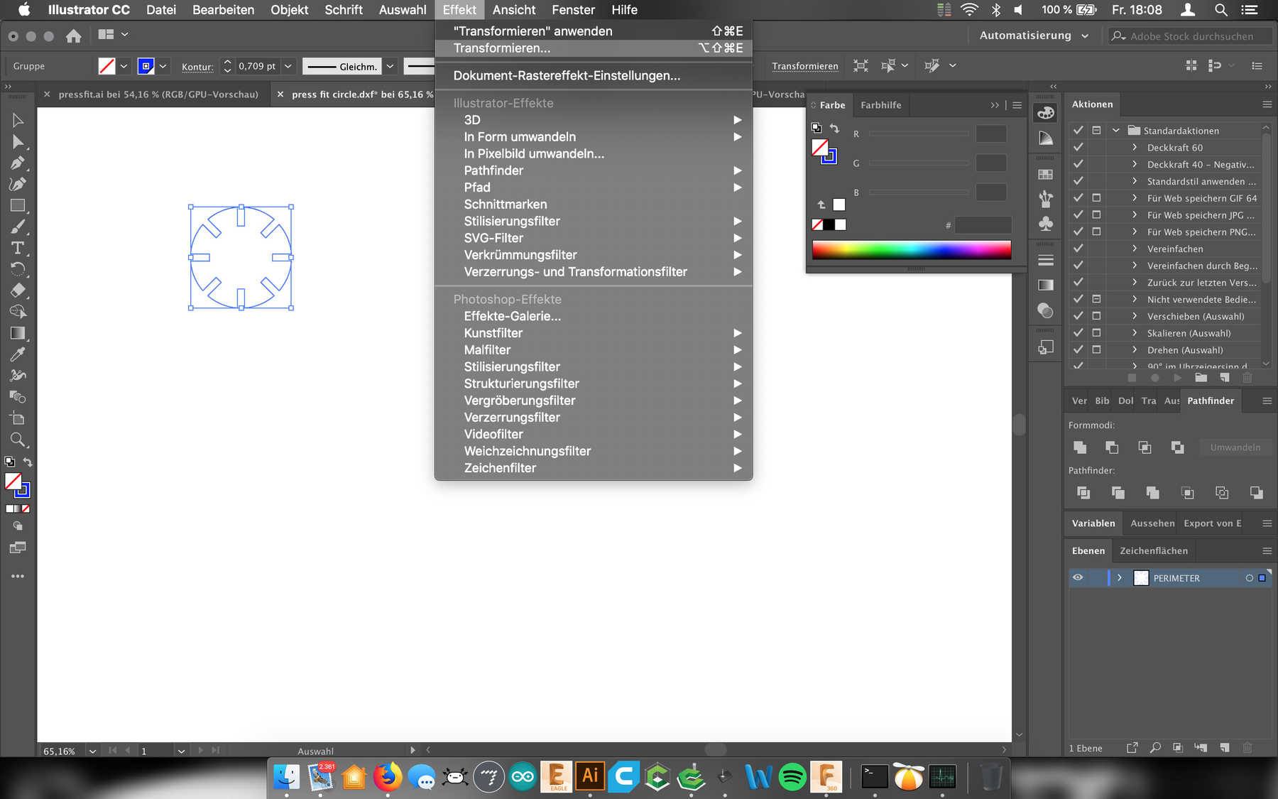
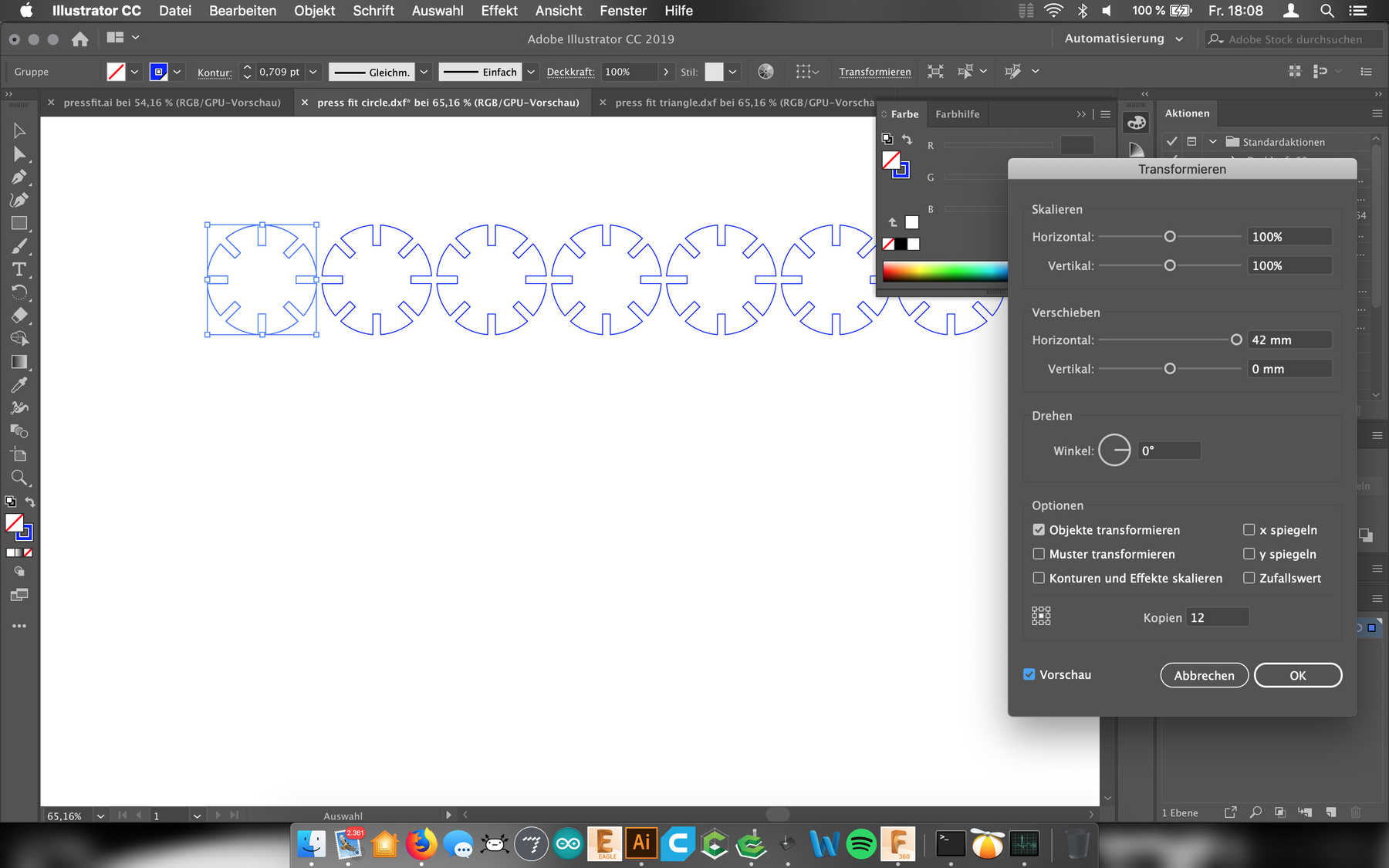
Another step is to multiply the individual models. For this, you can use the feature multiply-feature build in Adobe Illustrator. You can find it under Effect > Transform. Thus one can guarantee well that the contents are distributed.
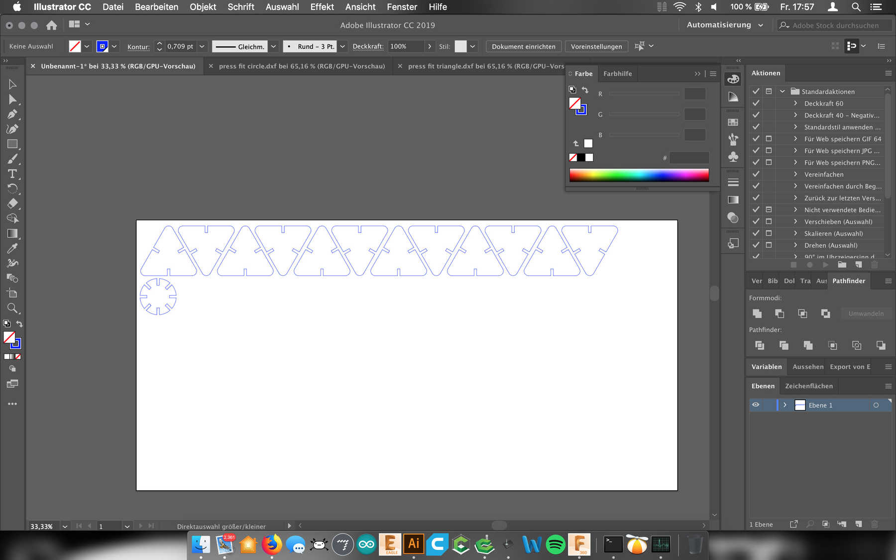
Afterward, I saved the Illustrator-file as an SVG-file and opened it with Visicut with the available settings for the laser cutter.
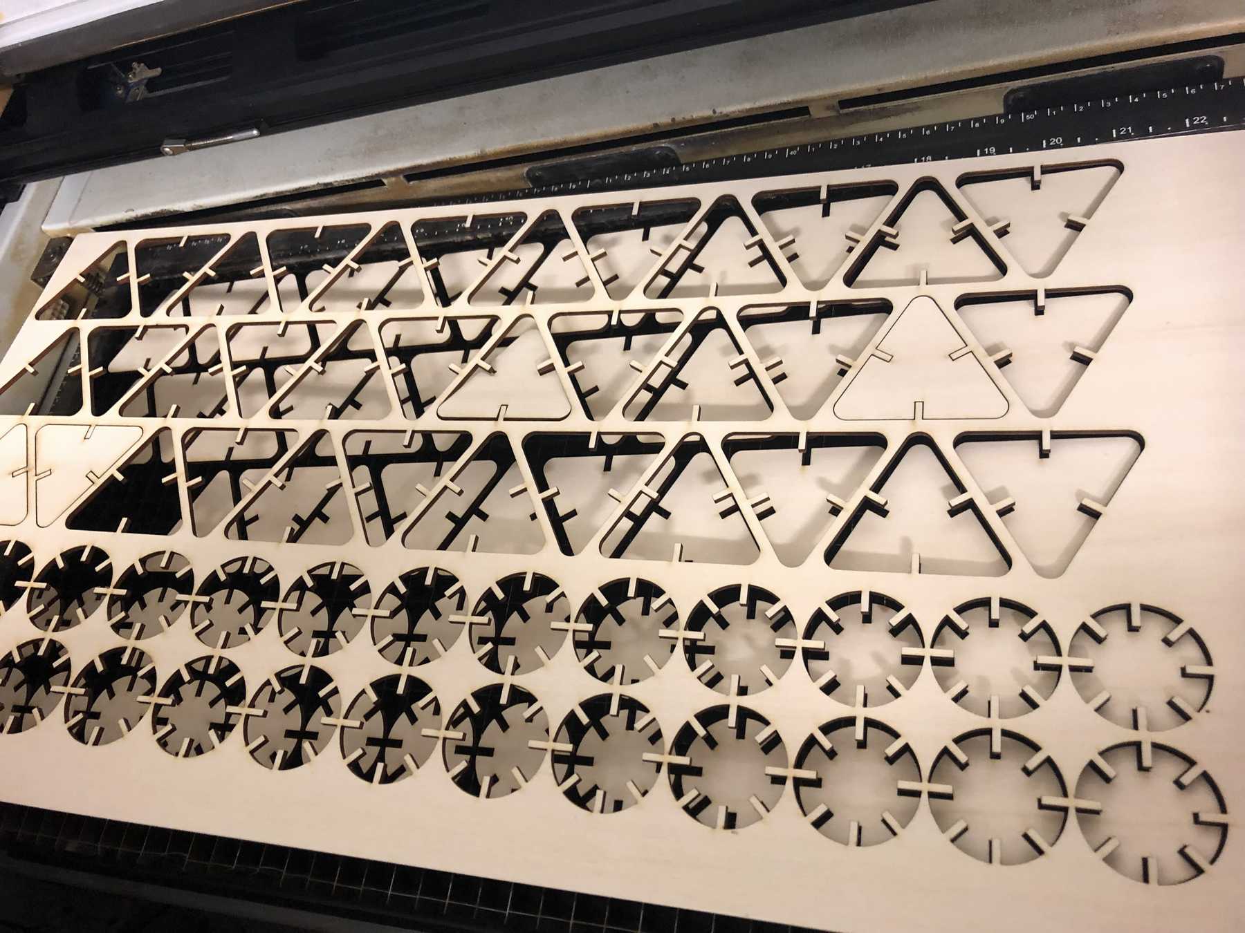
Testing and Cutting
To increase the fit I performed an iteration of the design. Finally, I started the “mass production”. This is documented in the following video.
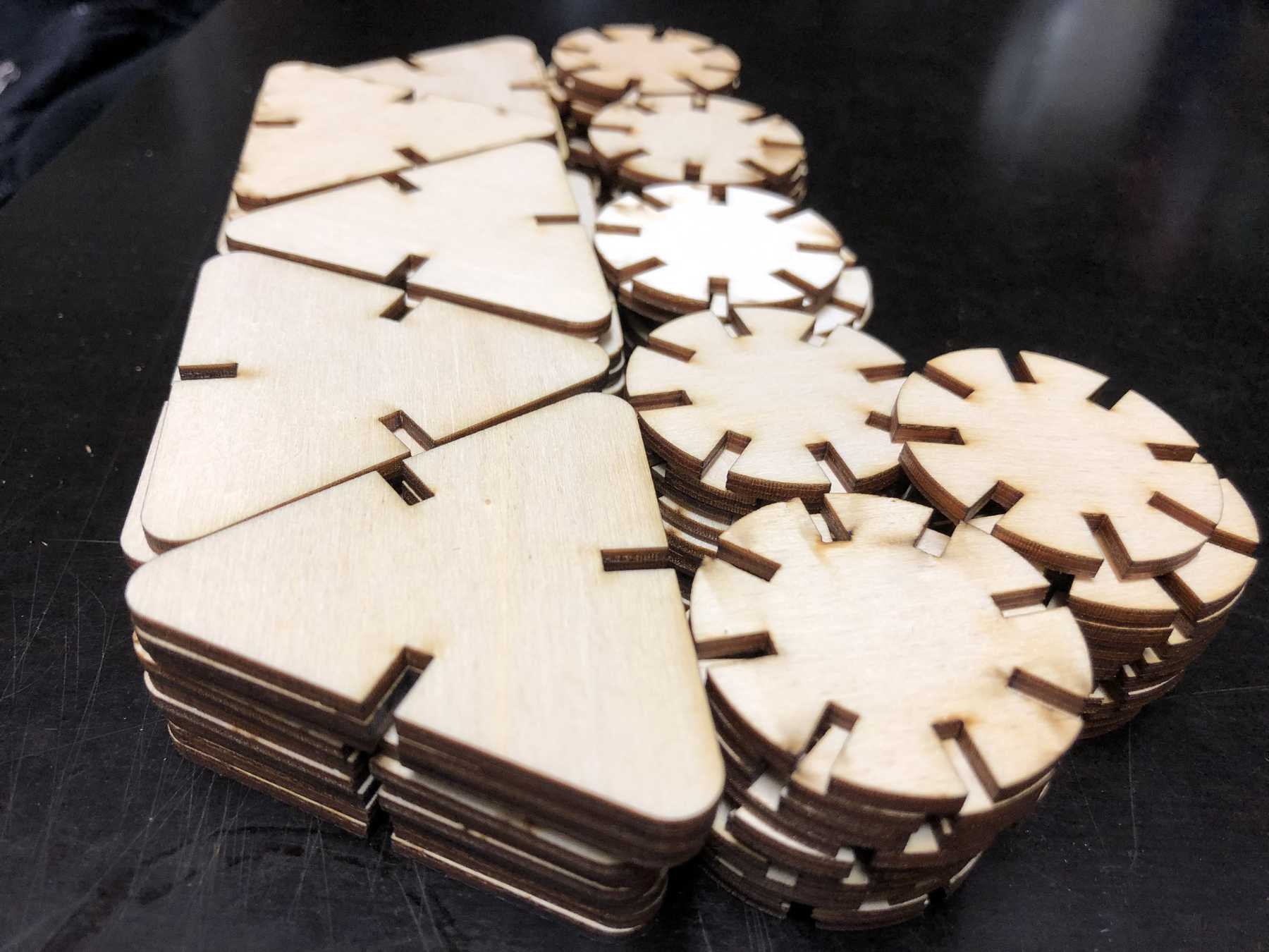
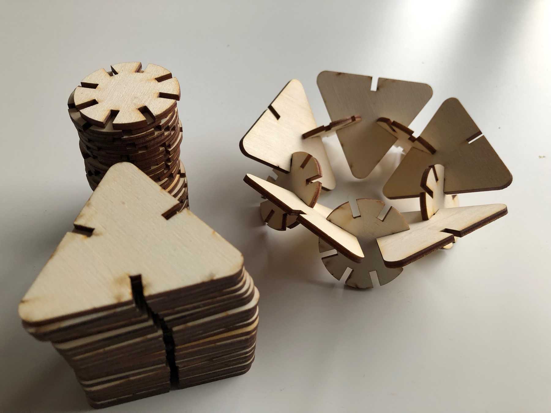
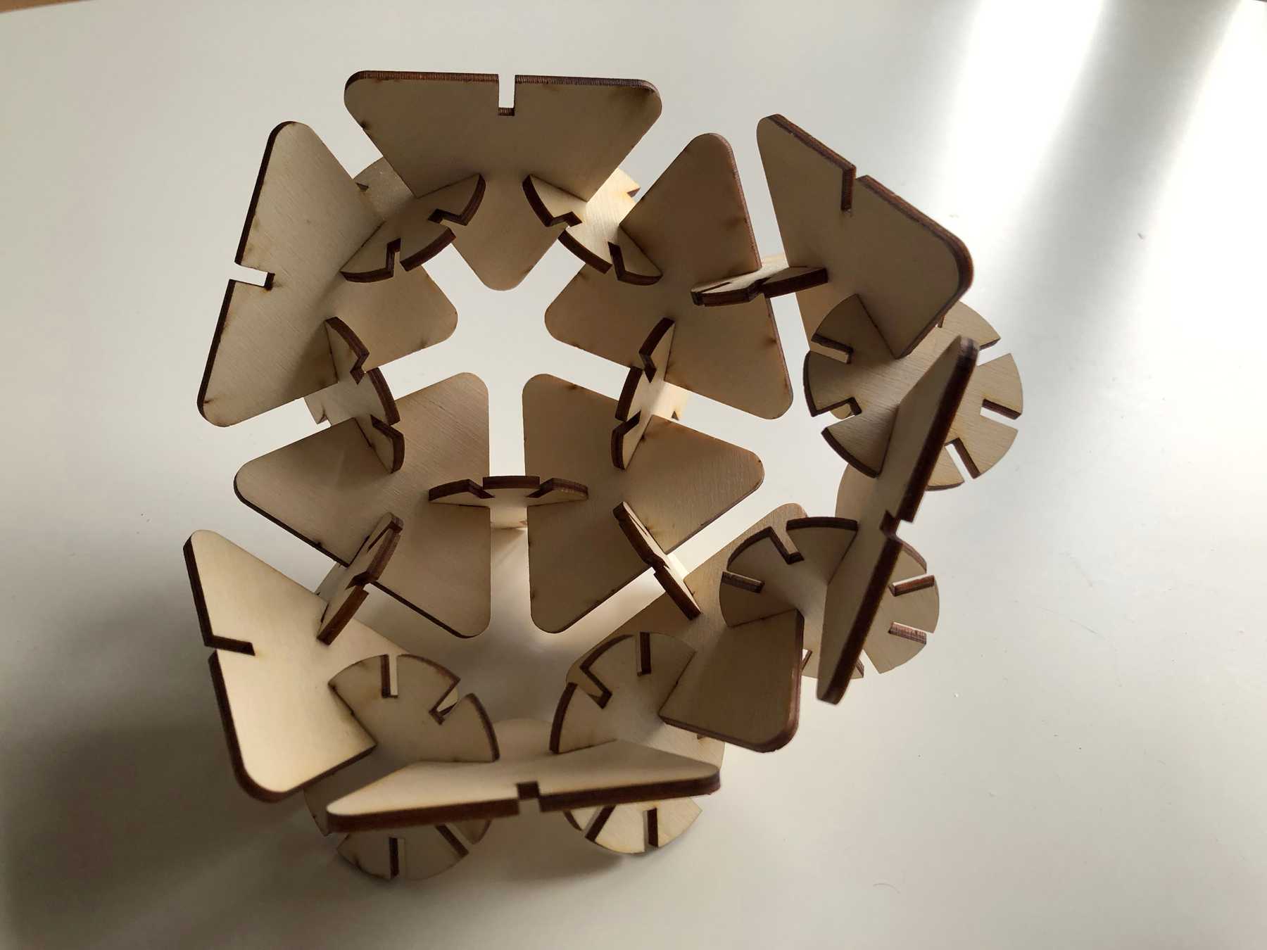
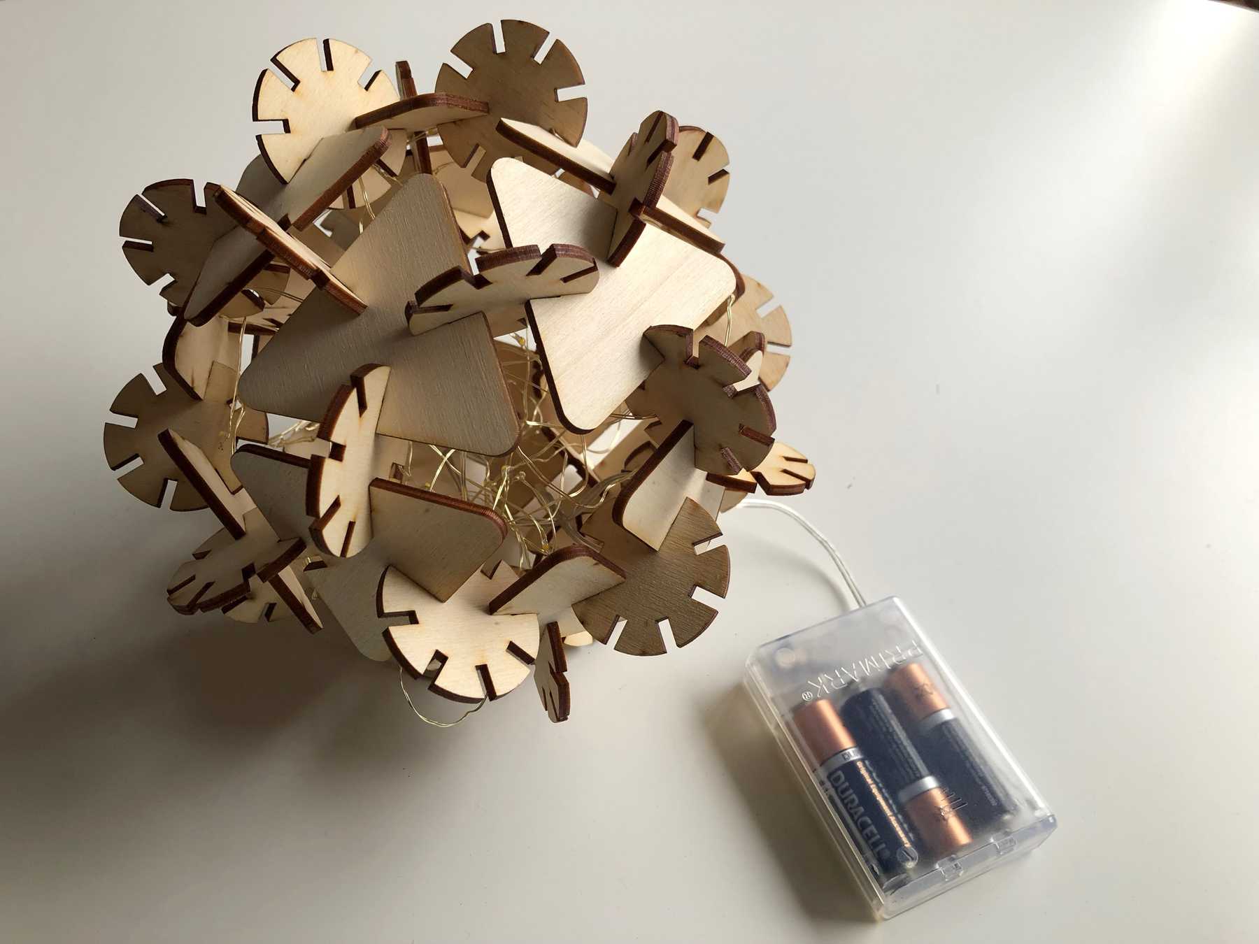
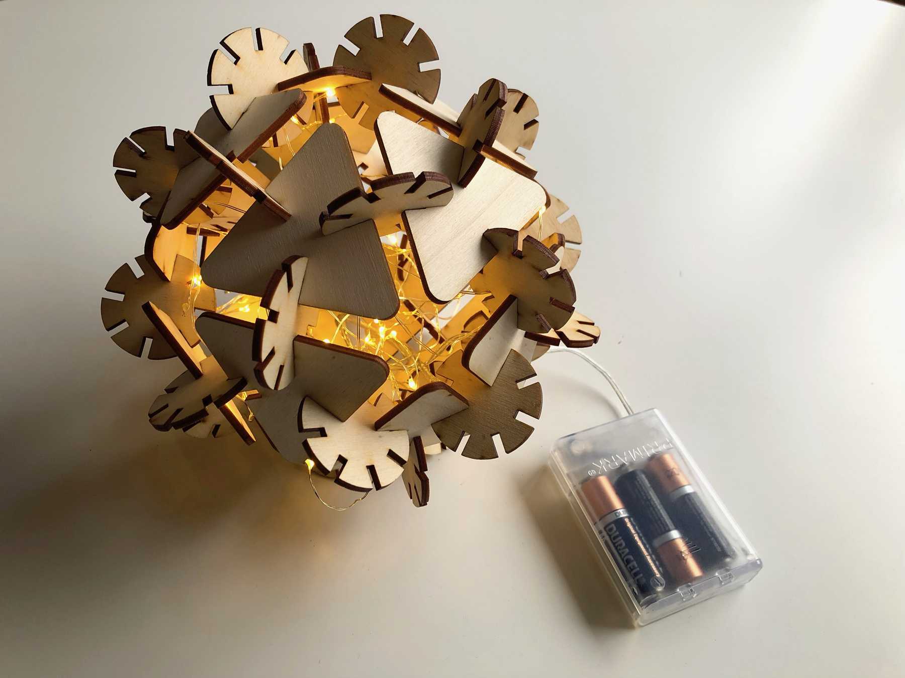
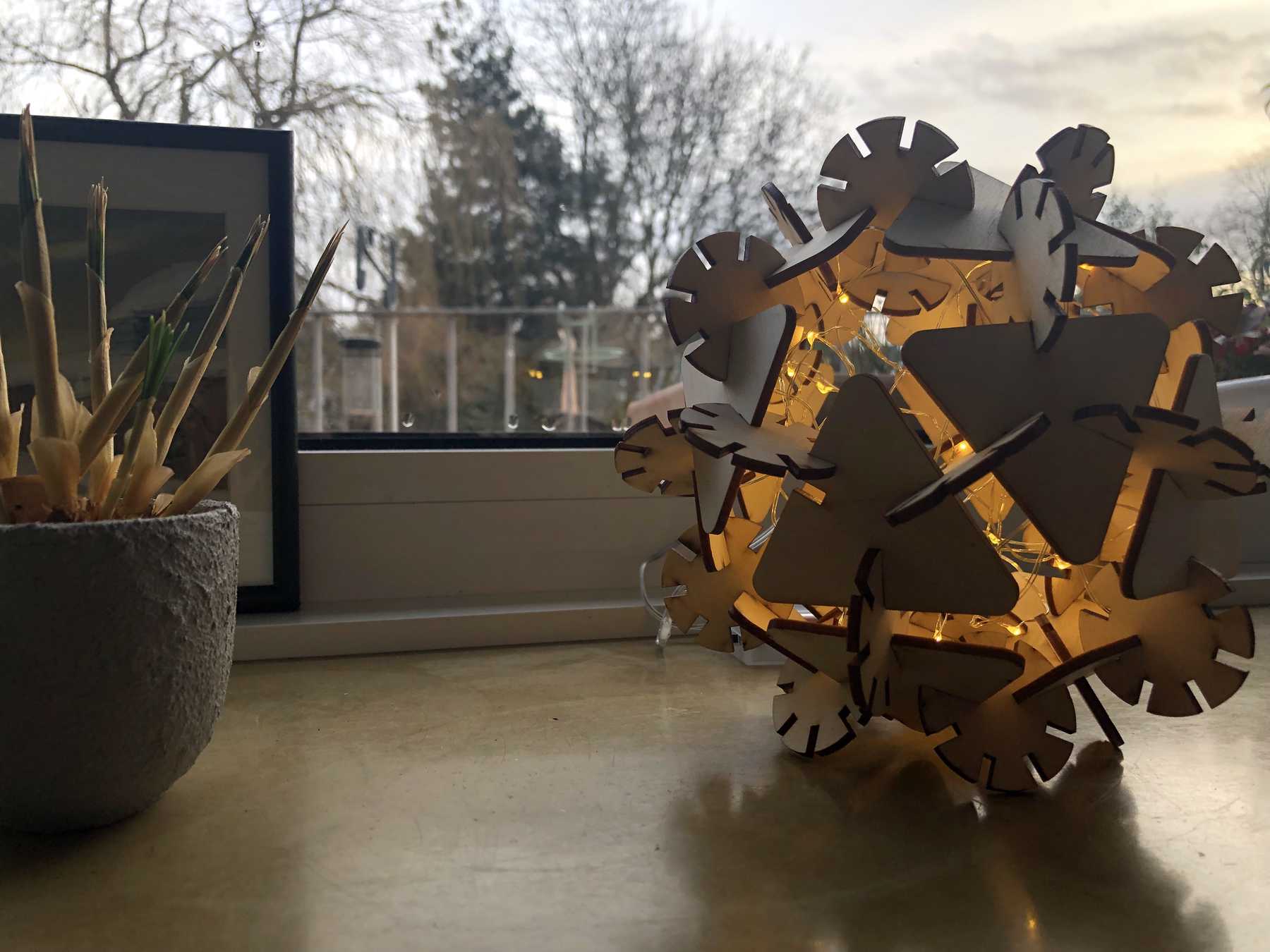
Results of the press-fit construction-kit
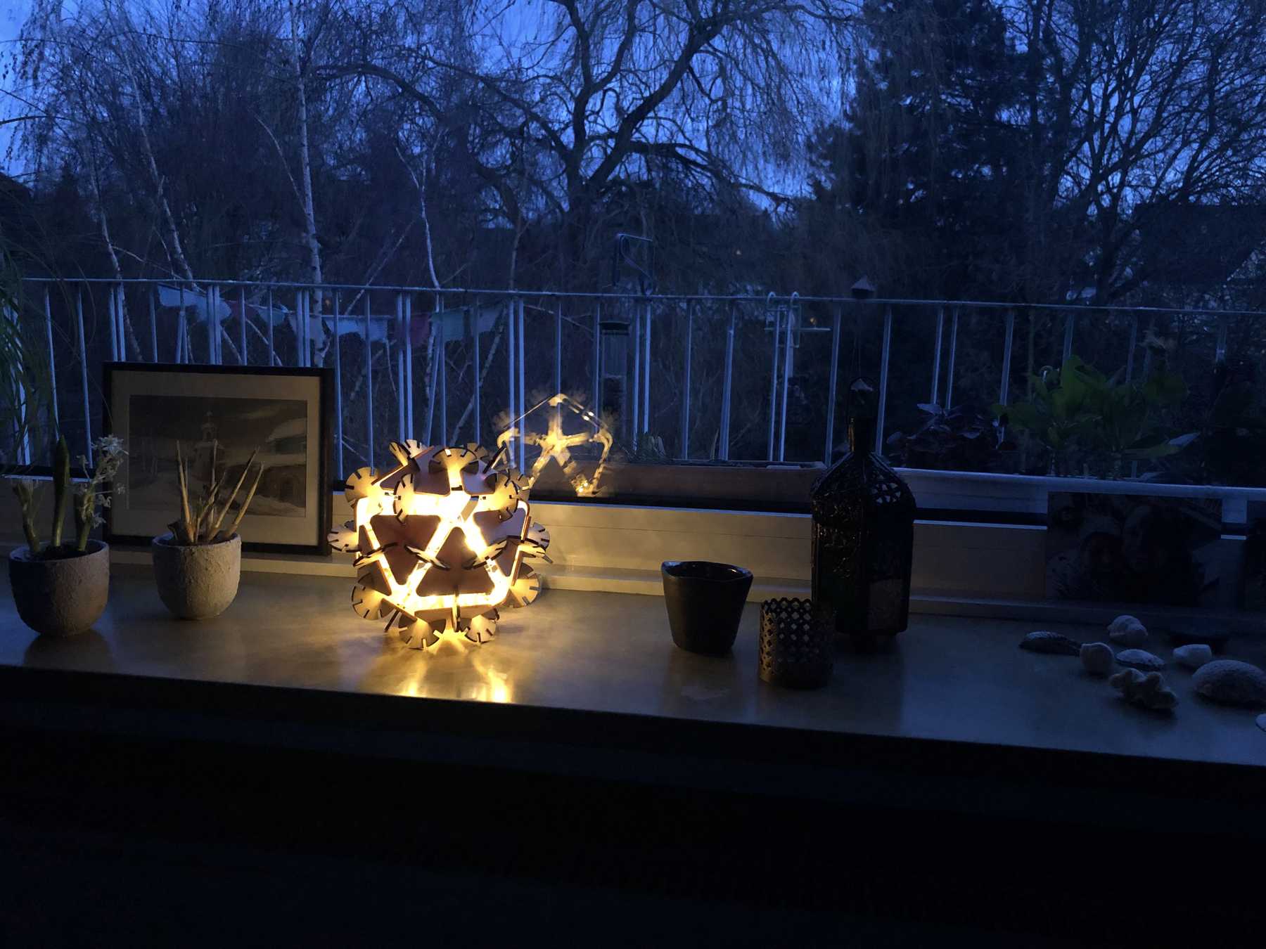
I followed different approaches and started different models based on the press-fit construction kit. However, from the beginning, I had in mind to build a small lamp, which has inside LEDs for the living room. A small gift to my girlfriend. The results can be seen below.

Vinyl cutter
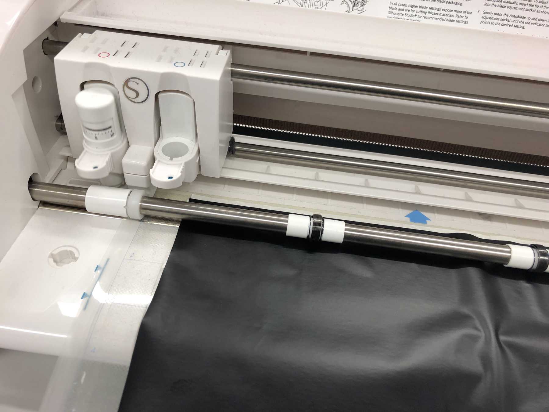
Another task was to create something with the vinyl cutter. I had the Cameo 3 from Silhouette at my disposal. This is a comparably cheap device, but you can make a lot of different things with it. You can process countless materials with a maximum width of 304.8 mm (12 inches). The maximum thickness is 78.75 mm.
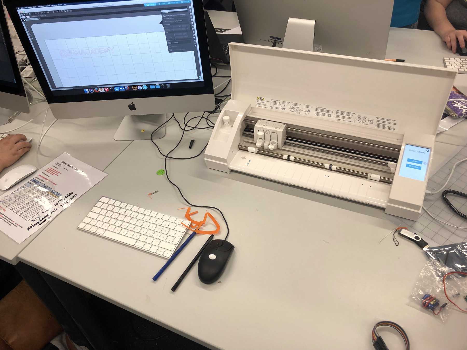
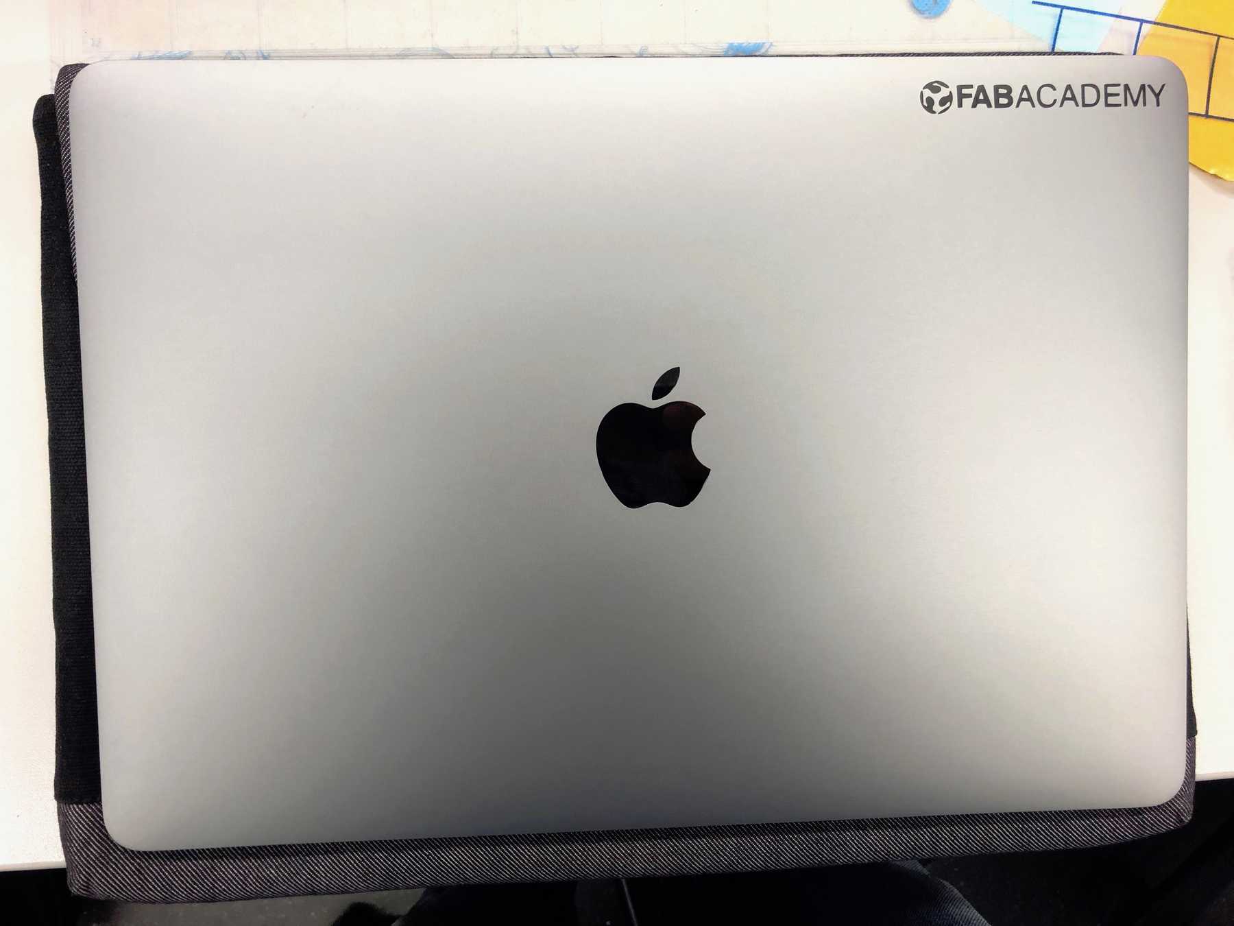
In the beginning, I had only stickers and printed T-shirts in my mind. Then I decided to create a sticker for my laptop. I wanted to show others, that I participated the Fab Academy and so I decided to make the logo of the Fab Academy in mat black which I wanted to place discreetly in a corner of my laptop. In the following you see the Silhouette Studio Software for editing the graphic before cutting.
![]()
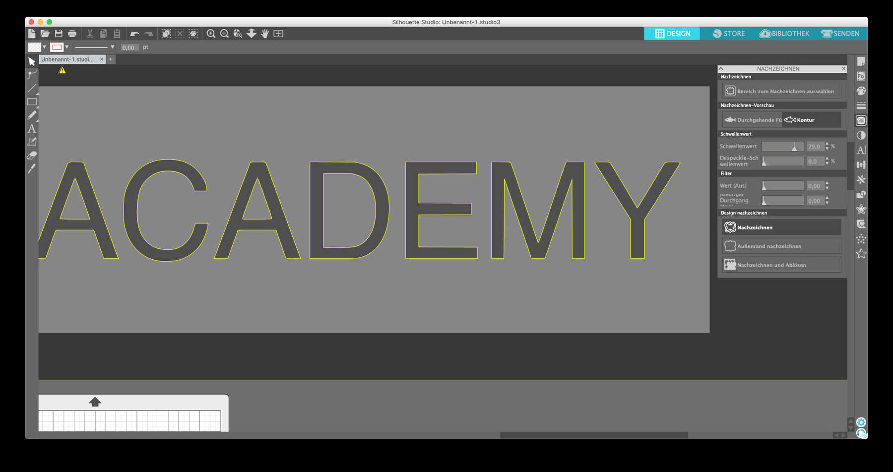
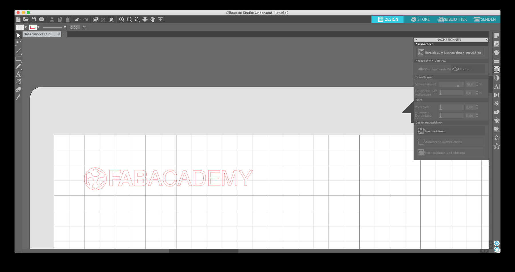
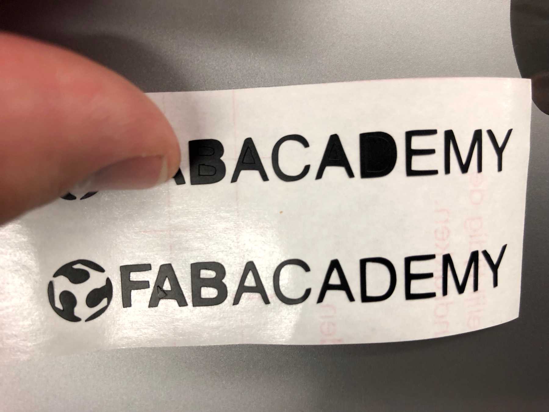
The logo I used was attached at the bottom. First I had to draw the logo with the software Silhouette, which is not so easy to use, and vectorized it. This turned out to be more difficult than expected.
After I cut out the logo I was able to transfer it to my laptop with the help of transfer film. I attached the results and the files below.
![]()
Download
Press-fit construction kit
Fusion 360 file
Illustrator file
SVG file
Vinylcutting