Output Devices
Week 12
This week I should make sure that I use an output device (individual asisgnment). Additionally I should measure the power consumption of an output device (group asisgnment).
Individual assignment
This chapter is divided into two parts. The first part deals with PCB design and can be found in input devices week. The second part is in this week and deals with the manufacturing process with another milling machine.
PCB production
The board for the weeks 11 and 12 were manufactured in two different ways. On the one hand I wanted to use the excellent LPKF ProtoMat S63, on the other hand I wanted to do every step of the production process. Starting with that is the Carbide Nomad 883 Pro in the DEZENTRALE. It has a very small cutting area of 200 x 200mm and runs the spindle with a speed of 2000-10,000 RPM, whereby the power is 70 Watt. We are currently trying to process small stainless steel with it. My colleague Jörg has already started milling PCBs with this machine and I wanted to try it out.
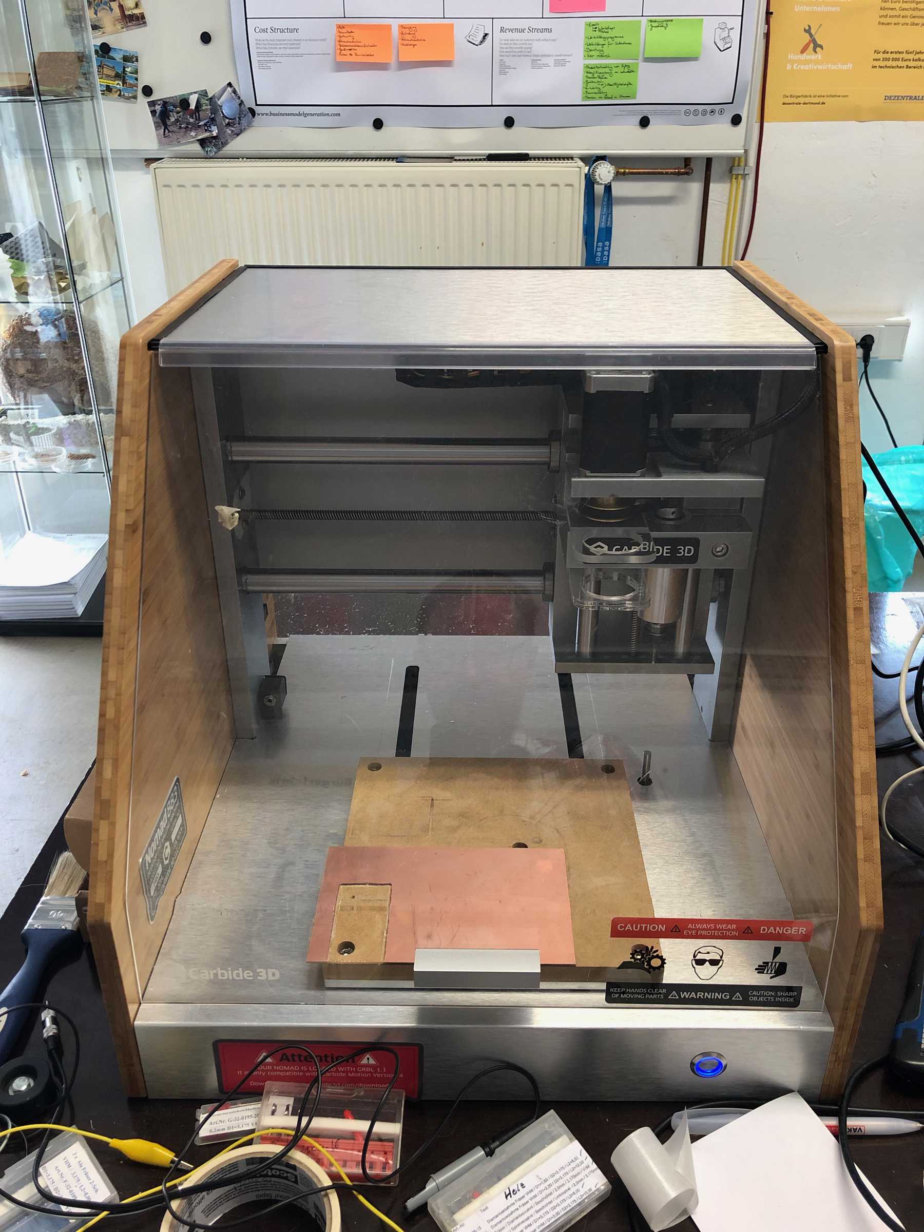
The Nomad 833 Pro was purchased for small workshops that simply take place externally and you don’t want a 3D printer that might take too long for such a component. In these cases, a subtractive machine can save a lot of time
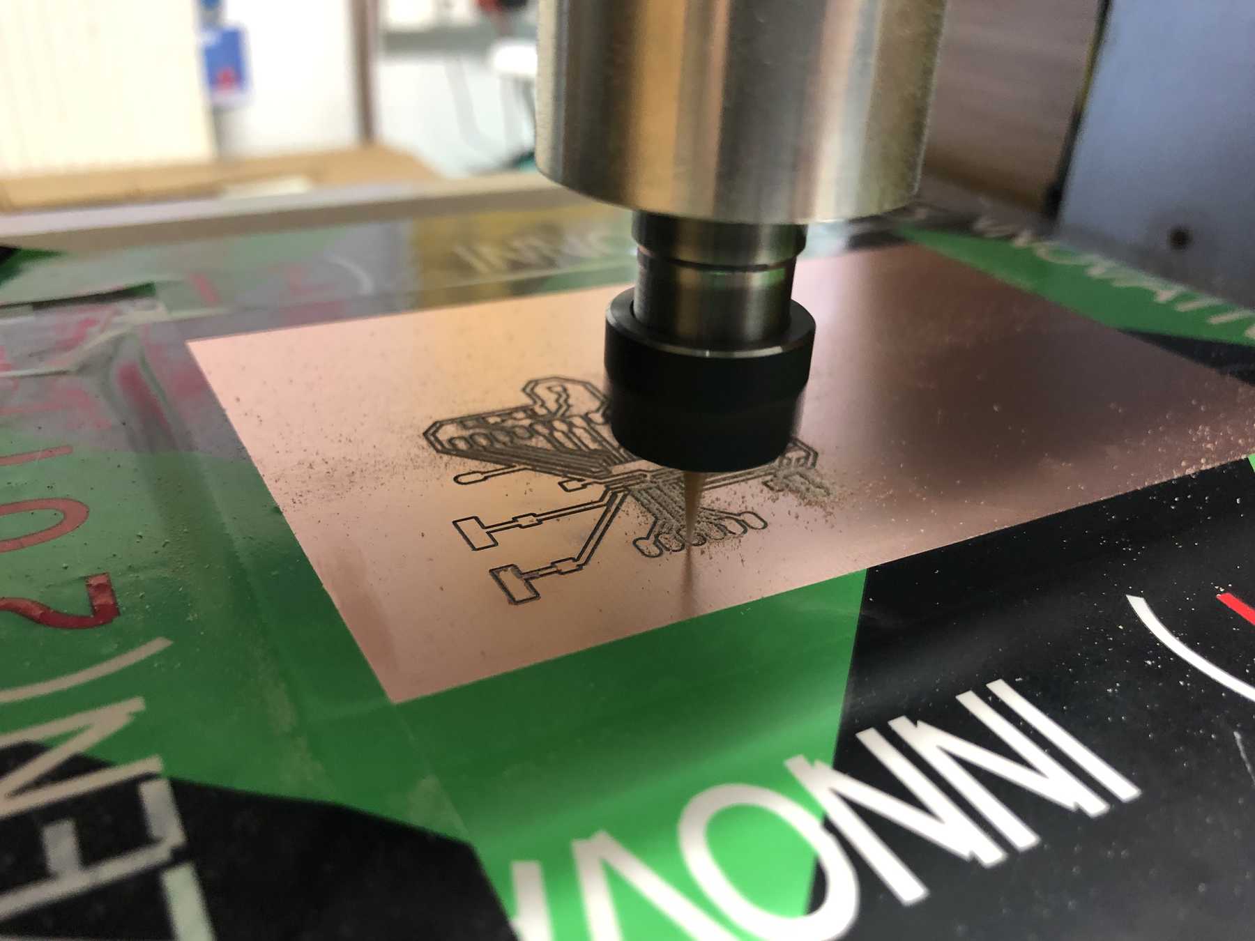
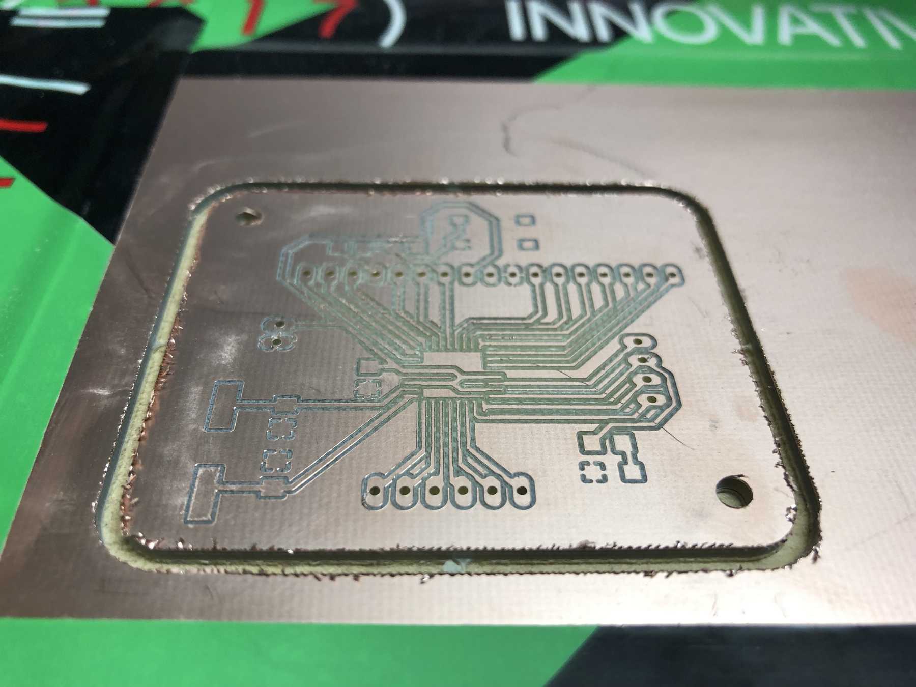
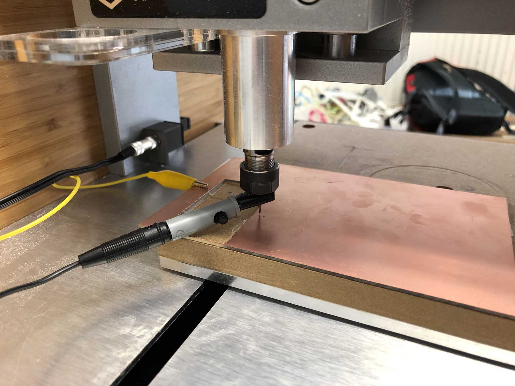
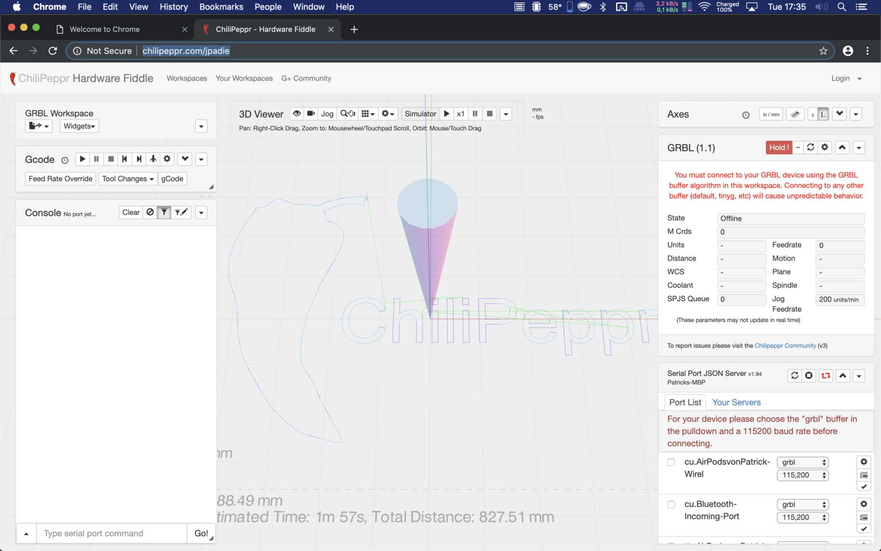
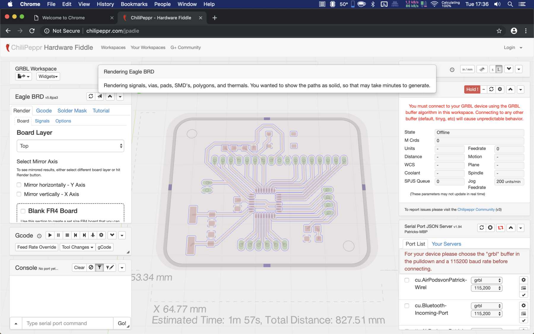
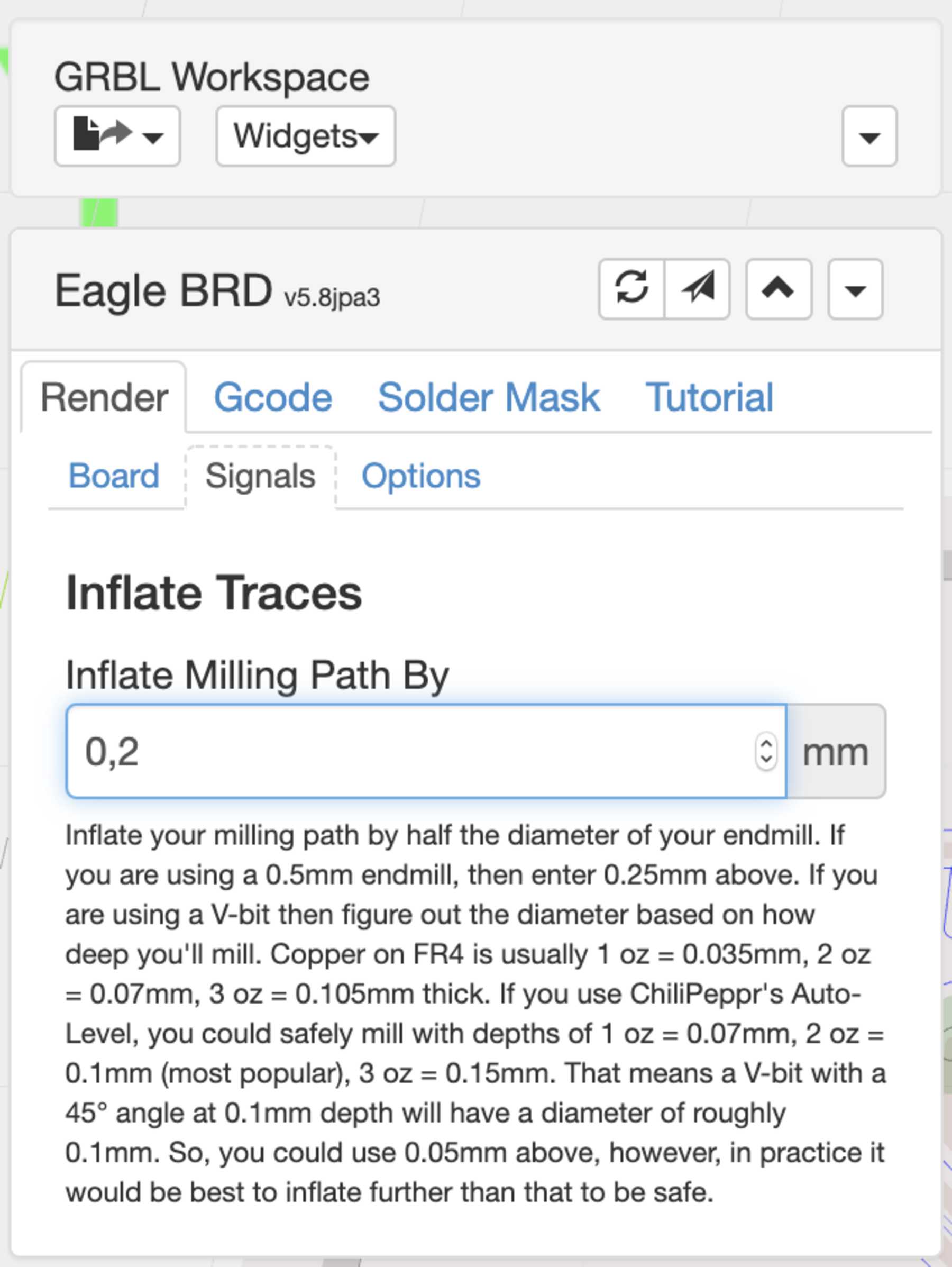
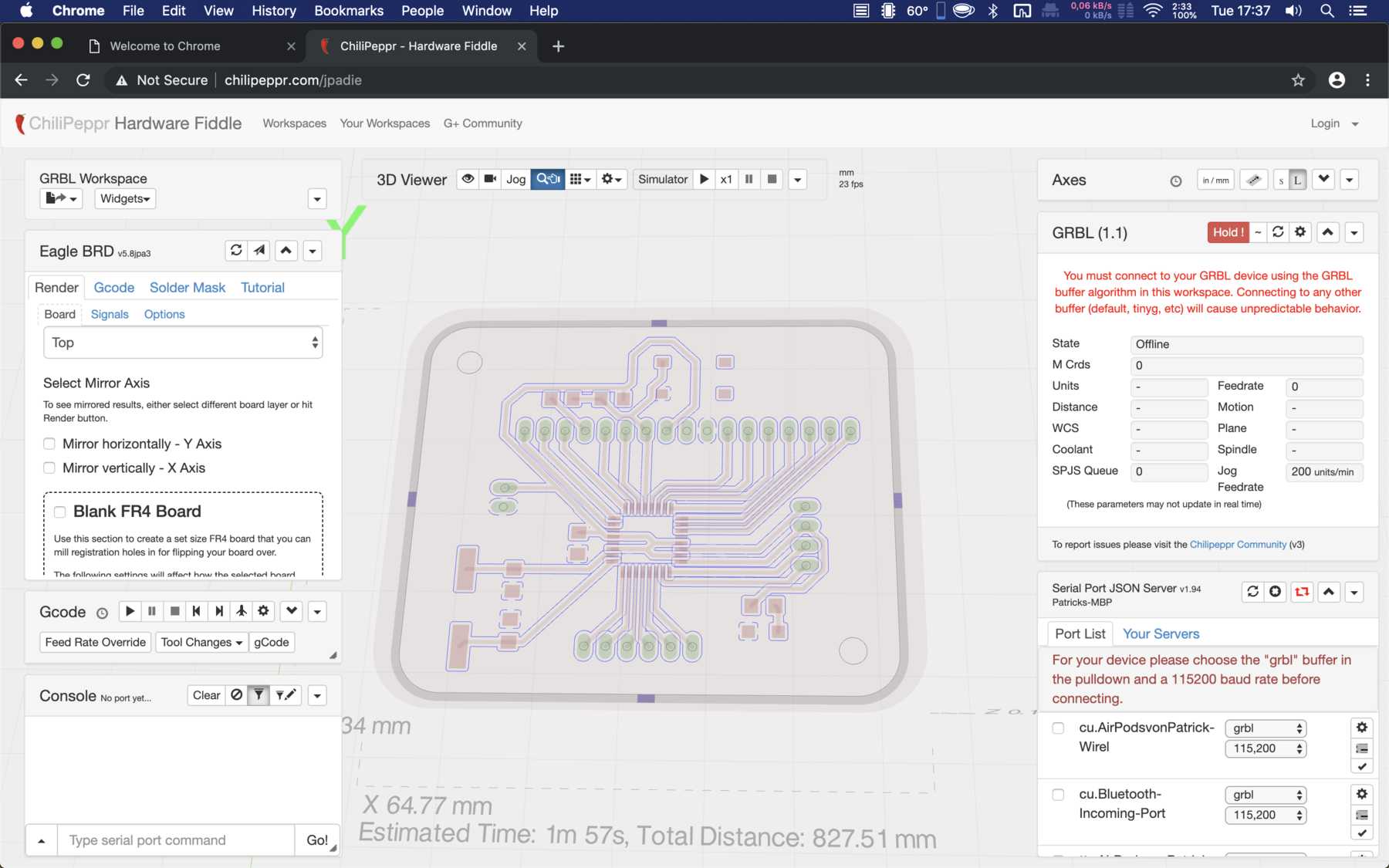
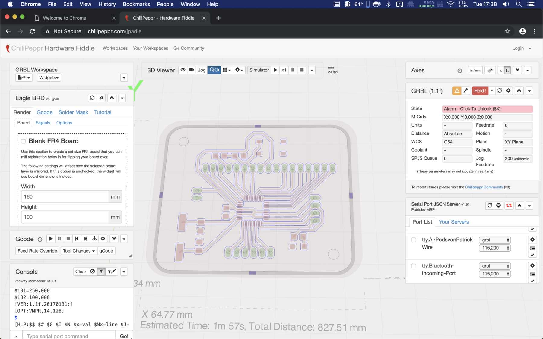
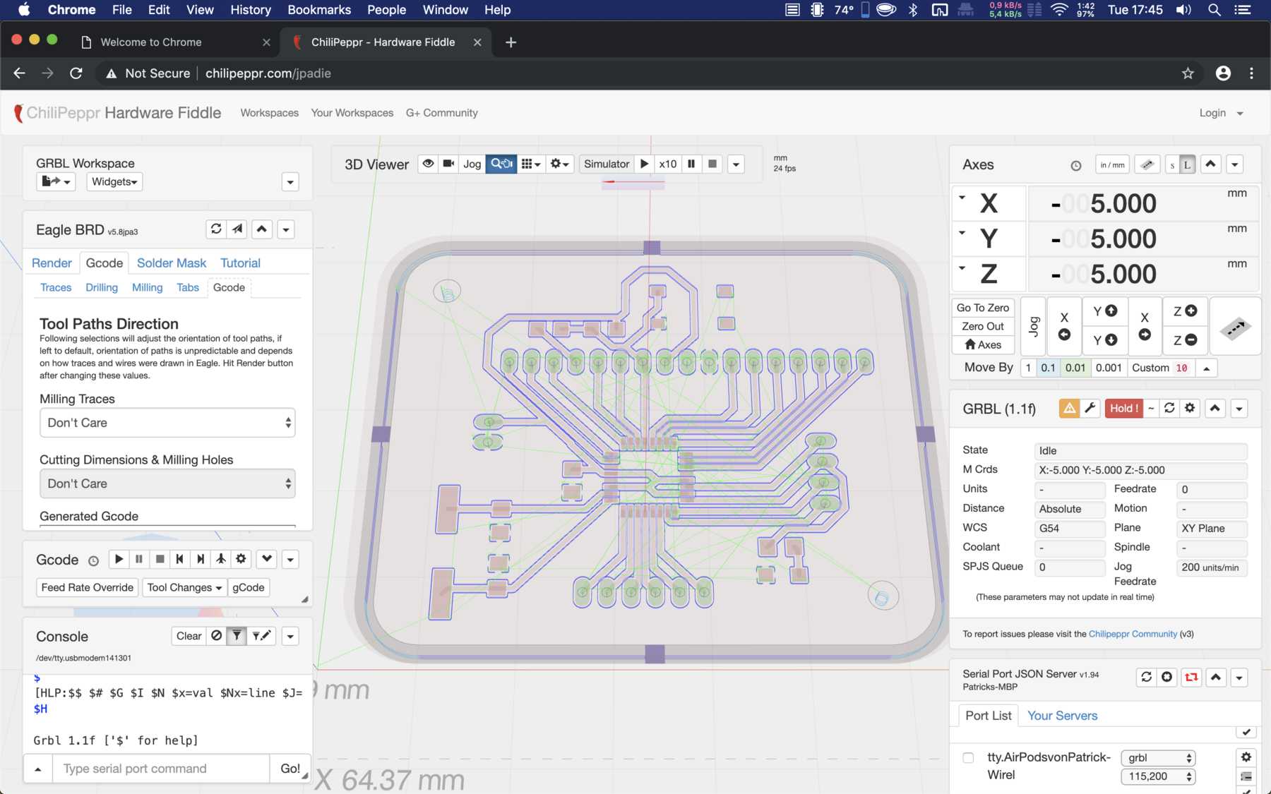
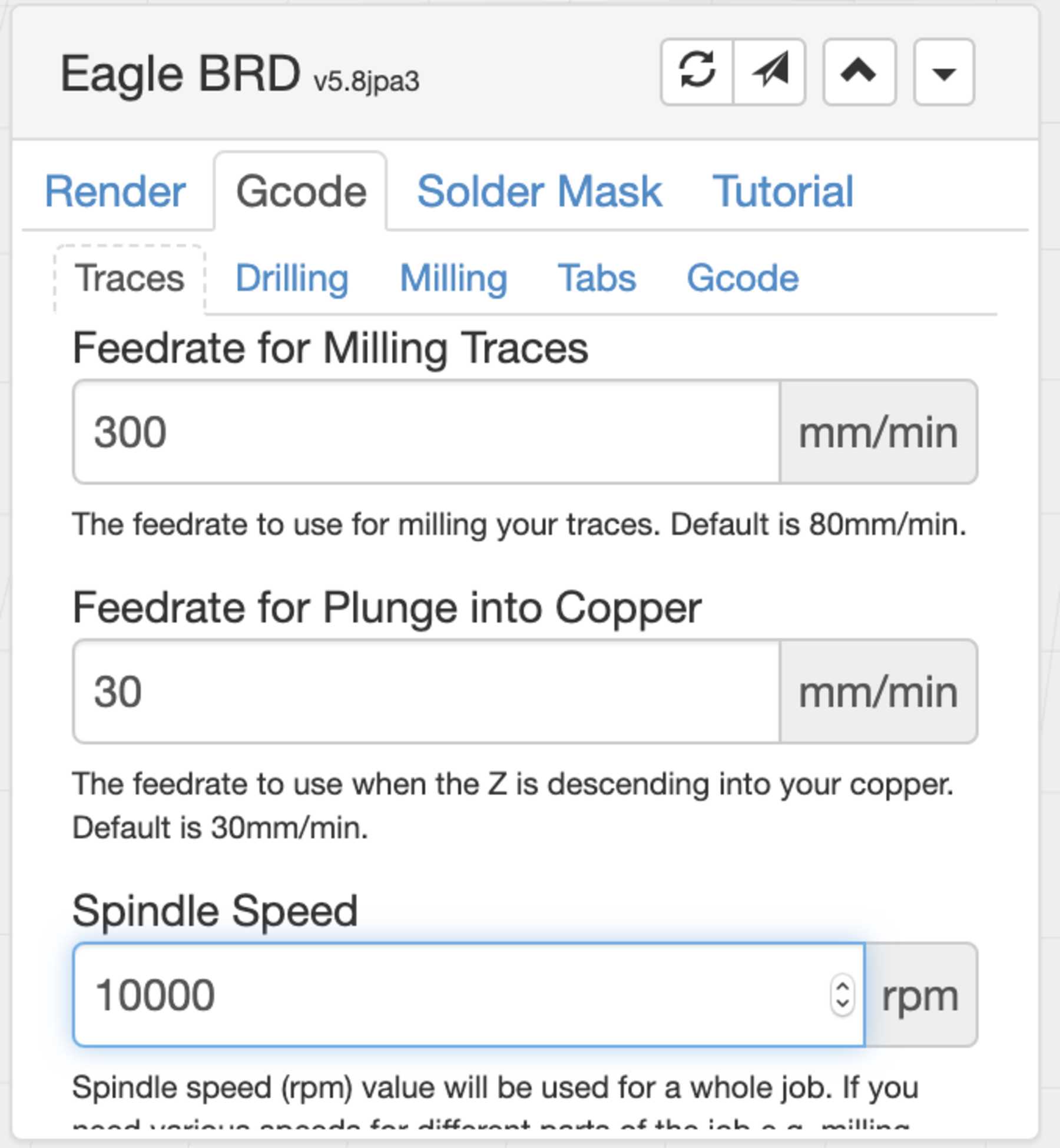
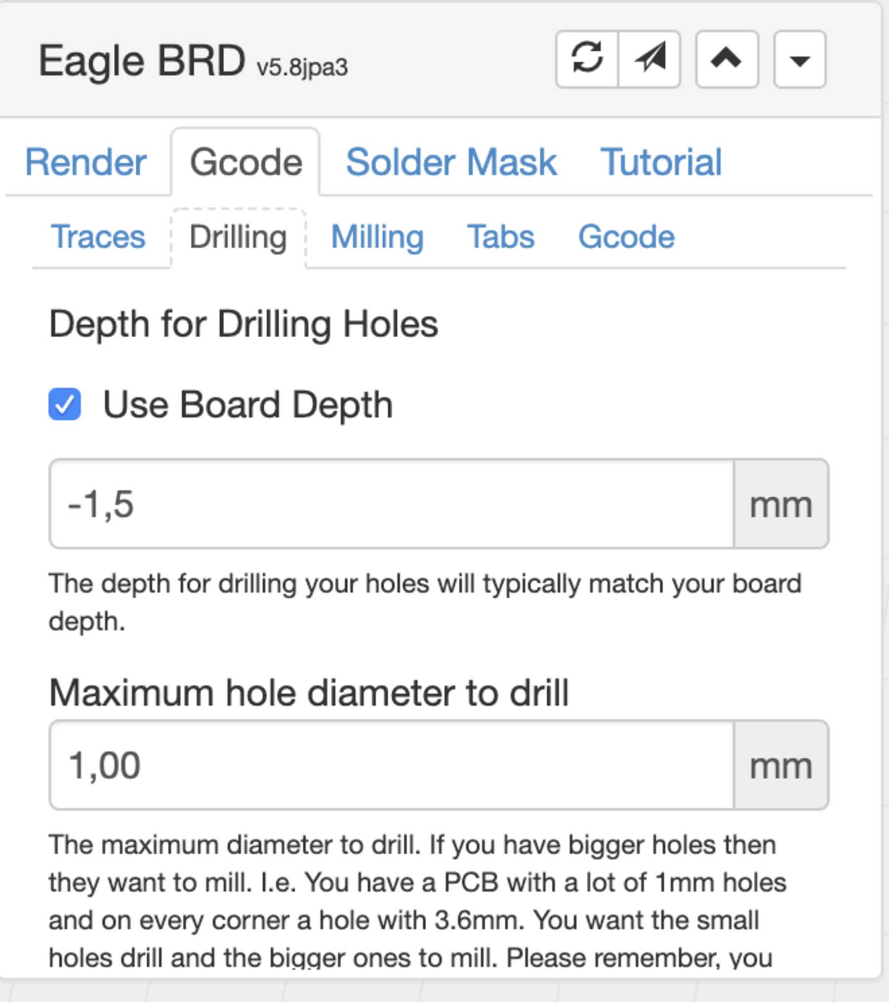
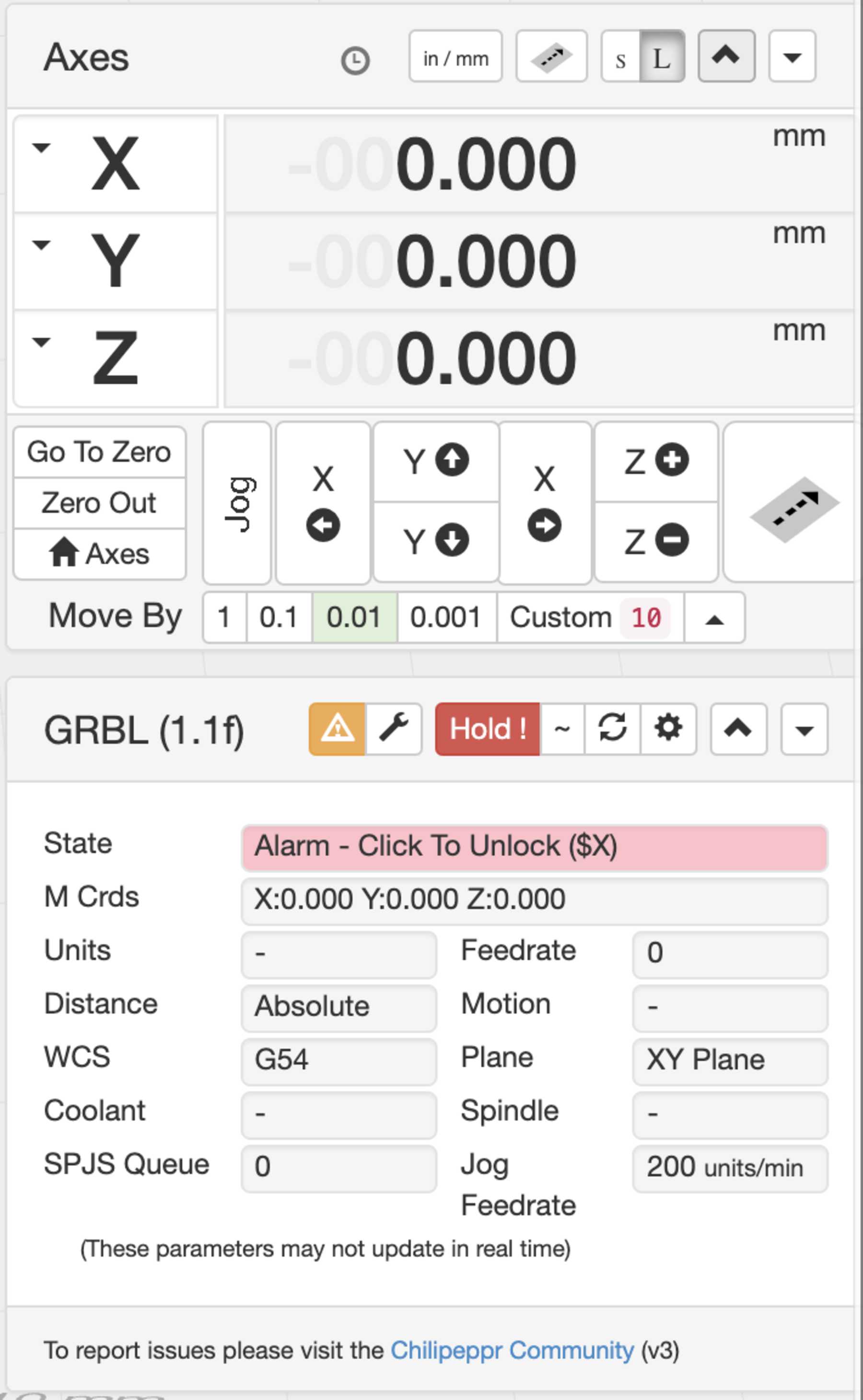
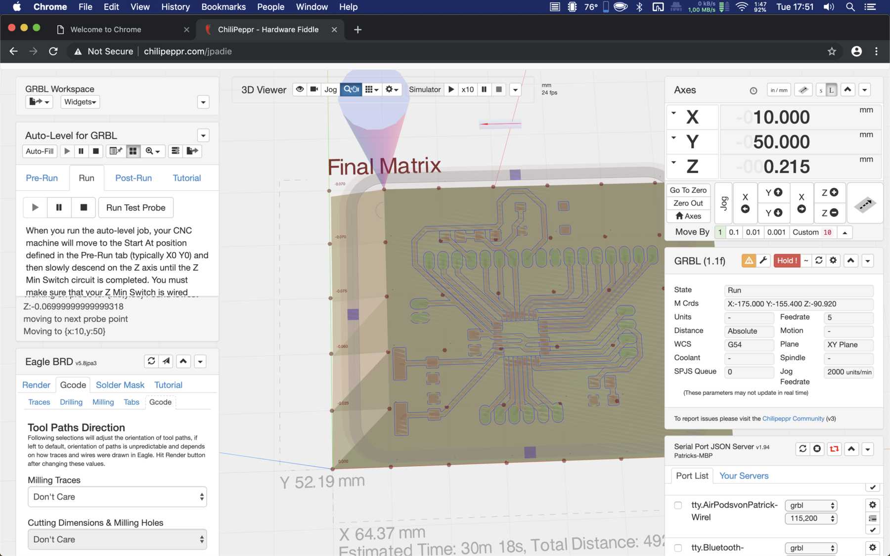
First I downloaded the software chilipeppr for Mac, set it up with the right settings for the Carbide Nomad 883 Pro, so that you can manufacture PCB boards. It starts with auto-levelling as there is no vacuum plate. Then each individual step is implemented by the user, such as milling or drilling. We used engraving gravers with a diameter of 0.1 mm and an angle of 15°. The result was not impressive compared to LPKF. Nevertheless, the correct parameters still have to be found for this machine so that a reproducible result is possible.
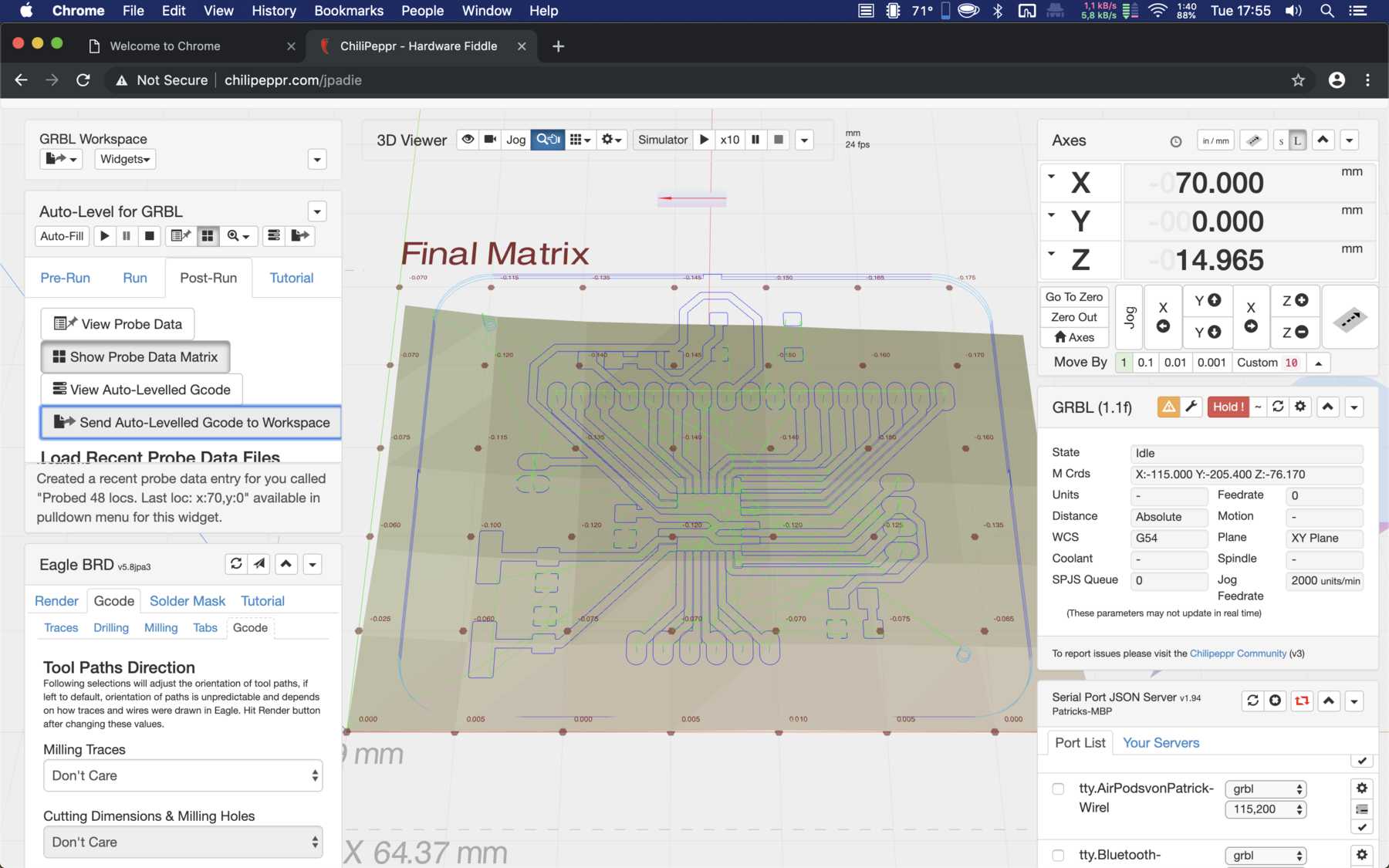
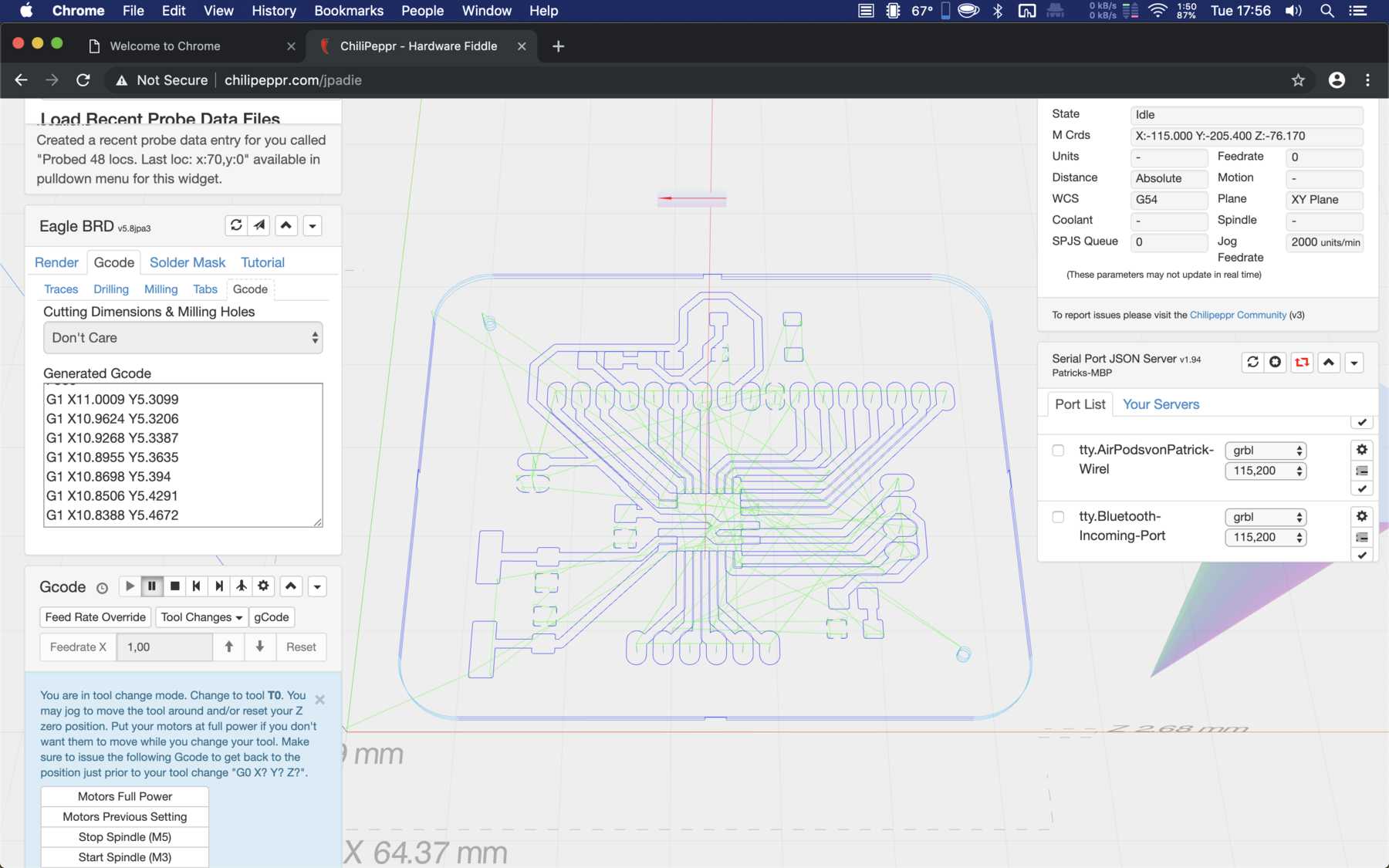
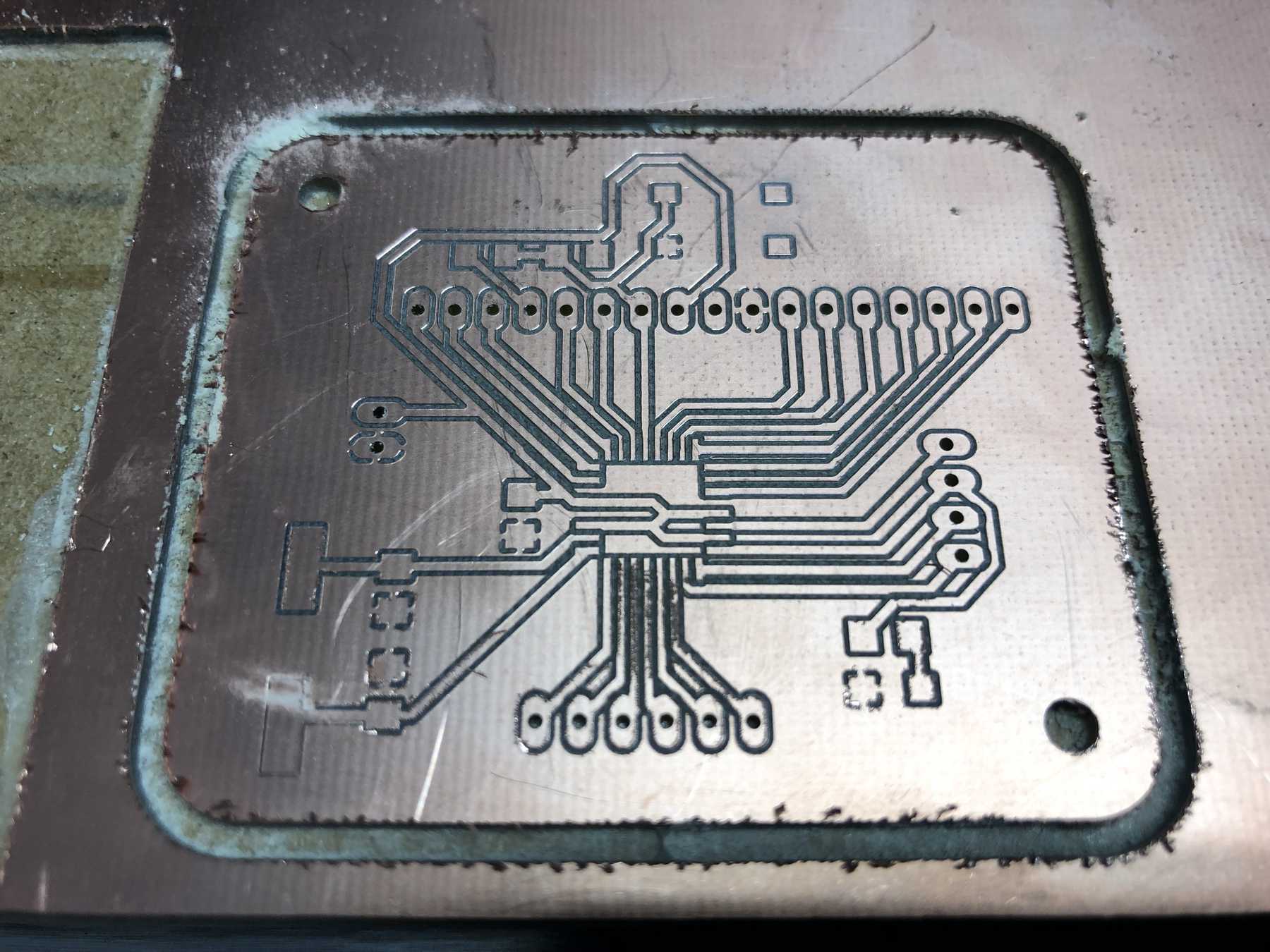
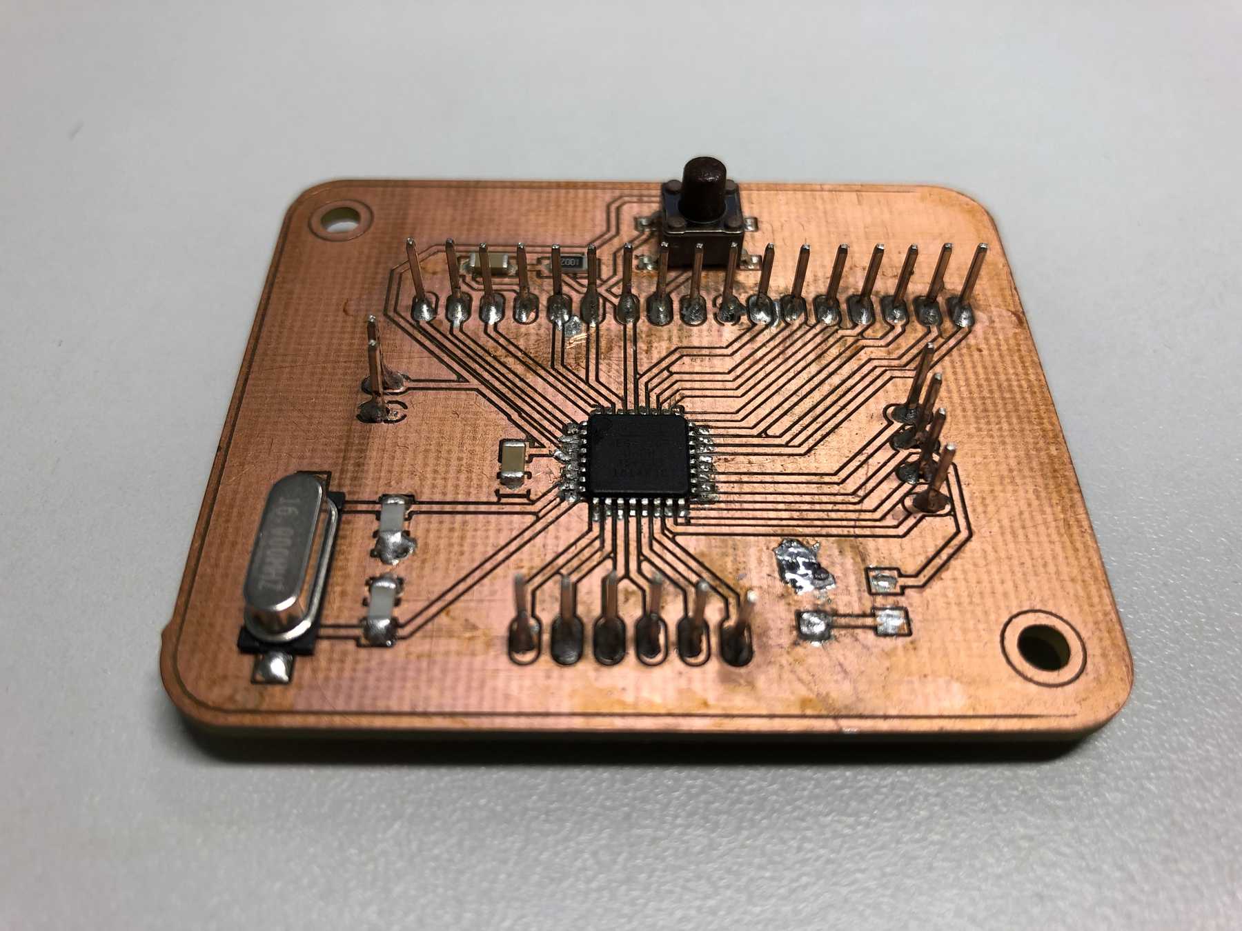
One conclusion: The LPKF ProtoMat S63 generates the more precise results, but the small Nomad 883 Pro is fun to work with. A final picture of the board.
Output device - force
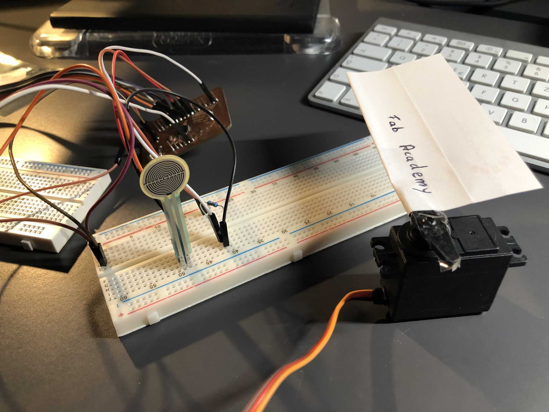
I found it useful to build the whole output devices assignment on the assignment from last week. I added an output-device to the input device, the FSR-sensor. If you now imagine that someone is sitting on a chair (link to the final project), then sometimes something mechanical has to happen. That’s why I decided to use the servo.
How a servo works is something I already explored in week 07 Electronics Design. I noticed that the< position changes depending on the pulse duration. Accordingly, the input value of the FSR sensor, which has a range from 0 to 1023, is now scaled down to a range from 0 to a maximum of 255 by the map function. With this adjustment, the FSR input value can now be used as the servo position value. The whole thing looks like this on an Arduino sketch:
#include <Servo.h>
Servo servo;
int reading;

void setup(void) {
  Serial.begin(9600);
  servo.attach(9);
  servo.write(0);
}

void loop(void) {
  reading = analogRead(A0);
  Serial.print("Sensor value = ");
  Serial.println(reading);
  int value = map(reading, 0, 1023, 0, 255);
  servo.write(value);
  delay(100);
}
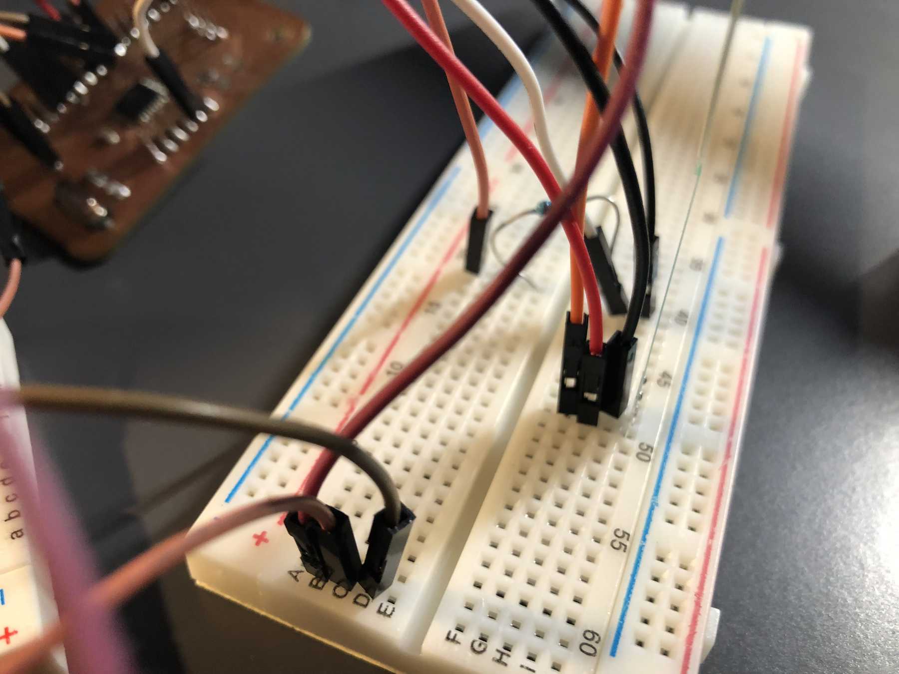
The whole device looked like this when connected:
Of course a video of the attempt to control a servo with an FSR:
Output device - LED
For the machine building week I definitely will need an LED or LED strip. In order to get to know this a bit better and to try out NeoPixel as well as FastLED, I have taken a look at several tutorials. I got the basis for this sketch from the Tweaking4All website, where I could find a structured and understandable tutorial about LED-Stripes and NeoPixel as well as FastLED.
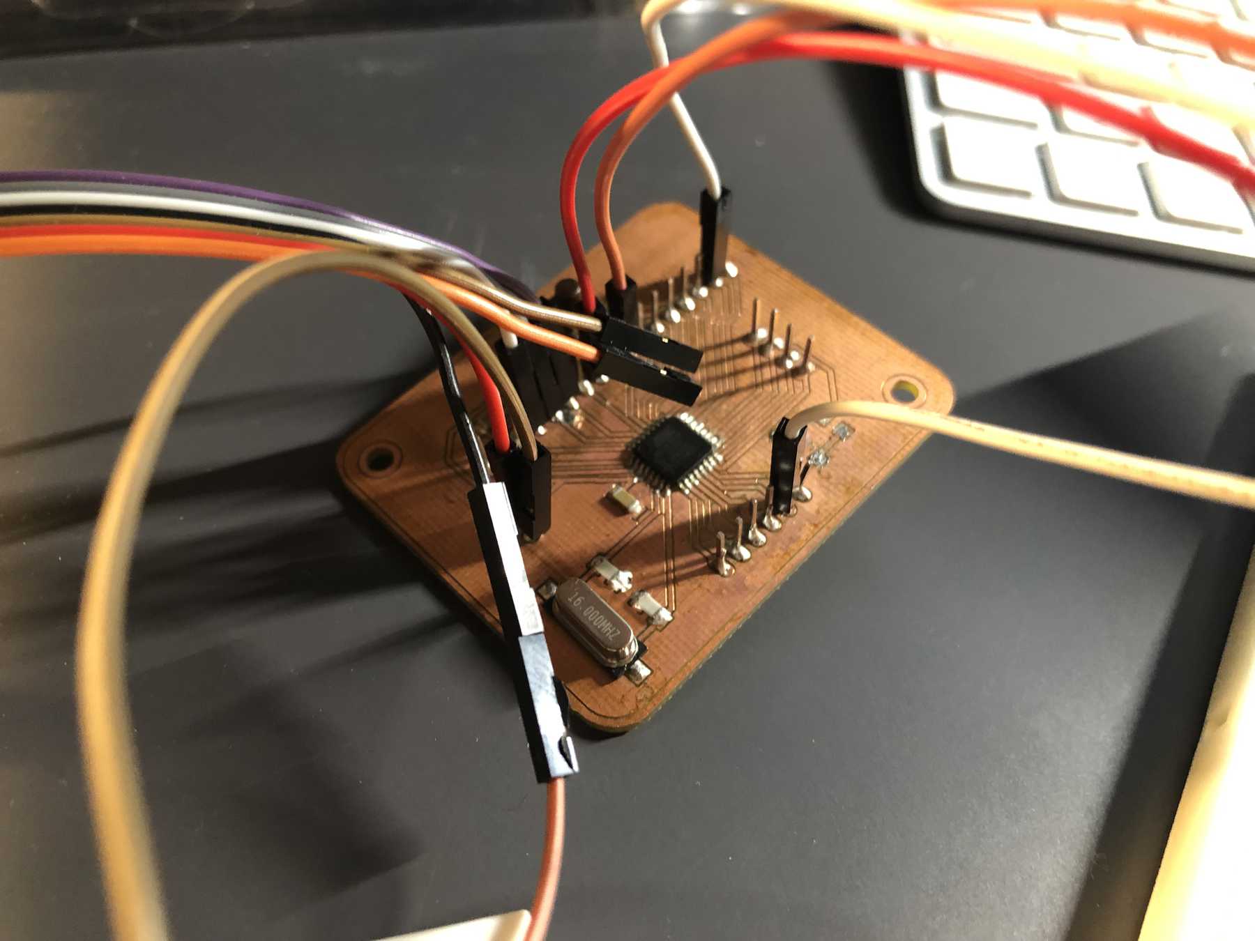
I built the whole thing with my own board and with an external power supply of 5V. With GND I had to connect them all via the breadboard. A short note: Always pay attention if you are Digital In or Digital Out (PI) at the LED stripe. Attached the Arduino Sketch:
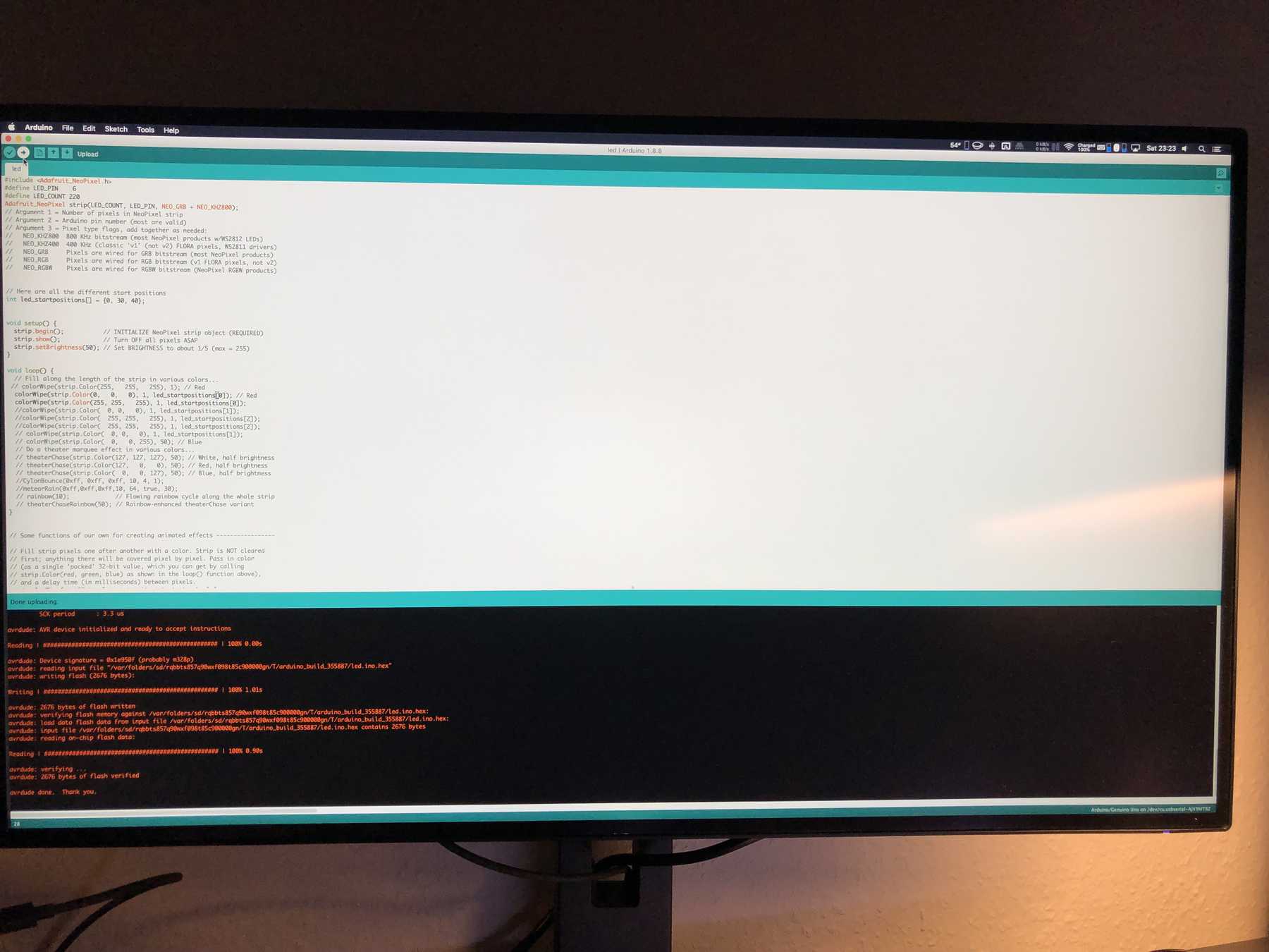
#include <Adafruit_NeoPixel.h>
#define LED_PIN    6
#define LED_COUNT 220
Adafruit_NeoPixel strip(LED_COUNT, LED_PIN, NEO_GRB + NEO_KHZ800);
// Argument 1 = Number of pixels in NeoPixel strip
// Argument 2 = Arduino pin number (most are valid)
// Argument 3 = Pixel type flags, add together as needed:
//   NEO_KHZ800  800 KHz bitstream (most NeoPixel products w/WS2812 LEDs)
//   NEO_KHZ400  400 KHz (classic 'v1' (not v2) FLORA pixels, WS2811 drivers)
//   NEO_GRB     Pixels are wired for GRB bitstream (most NeoPixel products)
//   NEO_RGB     Pixels are wired for RGB bitstream (v1 FLORA pixels, not v2)
//   NEO_RGBW    Pixels are wired for RGBW bitstream (NeoPixel RGBW products)

// Here are all the different start positions
int led_startpositions[] = {0, 30, 40};

void setup() {
  strip.begin();           // INITIALIZE NeoPixel strip object (REQUIRED)
  strip.show();            // Turn OFF all pixels ASAP
  strip.setBrightness(50); // Set BRIGHTNESS to about 1/5 (max = 255)
}

void loop() {
  colorWipe(strip.Color(0,   0,   0), 1, led_startpositions[0]); // Red
  colorWipe(strip.Color(255, 255,   255), 1, led_startpositions[0]);
}

// Some functions of our own for creating animated effects -----------------

// Fill strip pixels one after another with a color. Strip is NOT cleared
// first; anything there will be covered pixel by pixel. Pass in color
// (as a single 'packed' 32-bit value, which you can get by calling
// strip.Color(red, green, blue) as shown in the loop() function above),
// and a delay time (in milliseconds) between pixels.
void colorWipe(uint32_t color, int wait, int startnumber) {
  for(int i=startnumber; i<strip.numPixels(); i++) { // For each pixel in strip...
    strip.setPixelColor(i, color);         //  Set pixel's color (in RAM)
    strip.show();                          //  Update strip to match
    delay(wait);                           //  Pause for a moment
  }
}

void showStrip() {
 #ifdef ADAFRUIT_NEOPIXEL_H
   // NeoPixel
   strip.show();
 #endif
 #ifndef ADAFRUIT_NEOPIXEL_H
   // FastLED
   FastLED.show();
 #endif
}

void setPixel(int Pixel, byte red, byte green, byte blue) {
 #ifdef ADAFRUIT_NEOPIXEL_H
   // NeoPixel
   strip.setPixelColor(Pixel, strip.Color(red, green, blue));
 #endif
 #ifndef ADAFRUIT_NEOPIXEL_H
   // FastLED
   leds[Pixel].r = red;
   leds[Pixel].g = green;
   leds[Pixel].b = blue;
 #endif
}

void setAll(byte red, byte green, byte blue) {
  for(int i = 0; i < LED_COUNT; i++ ) {
    setPixel(i, red, green, blue);
  }
  showStrip();
}
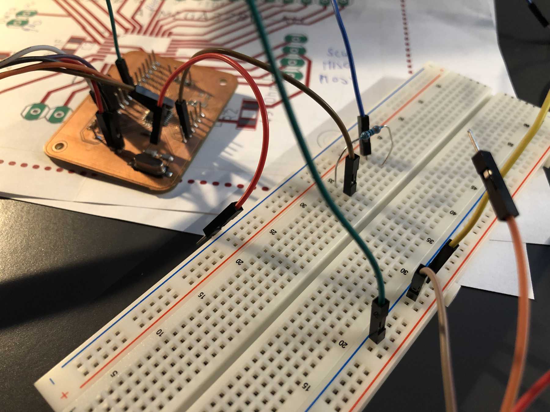
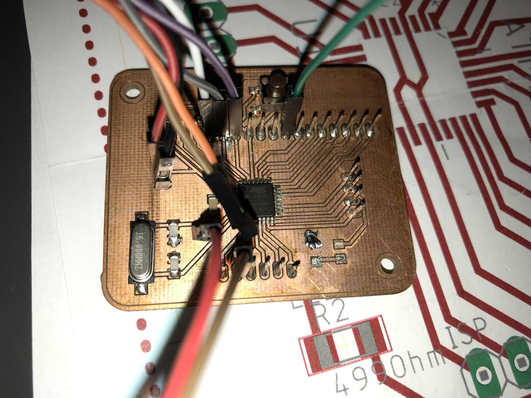
It was connected like this:
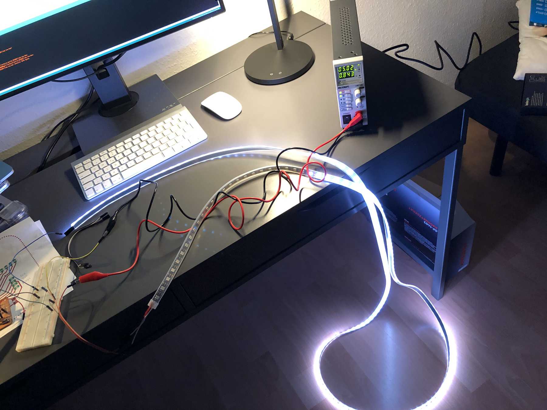
The video shows what the above looks like in real life:
Group assignment
Measure the power consumption
In the group task we should determine the power consumption. I had two approaches. First, I used a power supply in the output device week to determine the power consumption. The week before I detected an input device regarding the power consumption via a multimeter. I was interested in the power consumption of a gyroscope.
I’ll start with the power supply: First I have a look at the datasheet/manual of my Voltcraft power supply. It is the model LSP-1403. There are three preset output ranges from 0 - 16 V, 0 - 27 V or 0 - 36 V to choose from. The max. output power in all three ranges is 80 Watt.
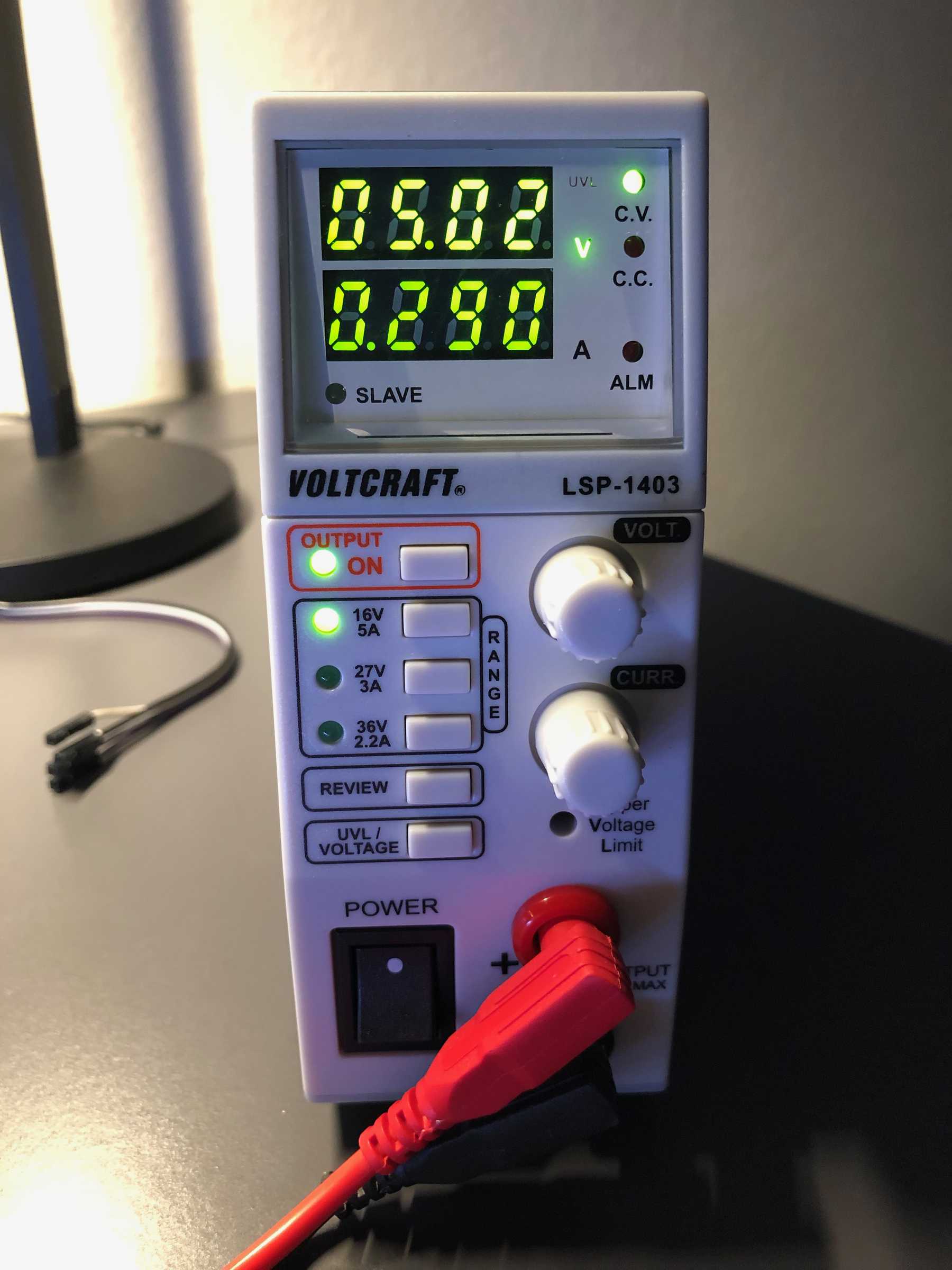
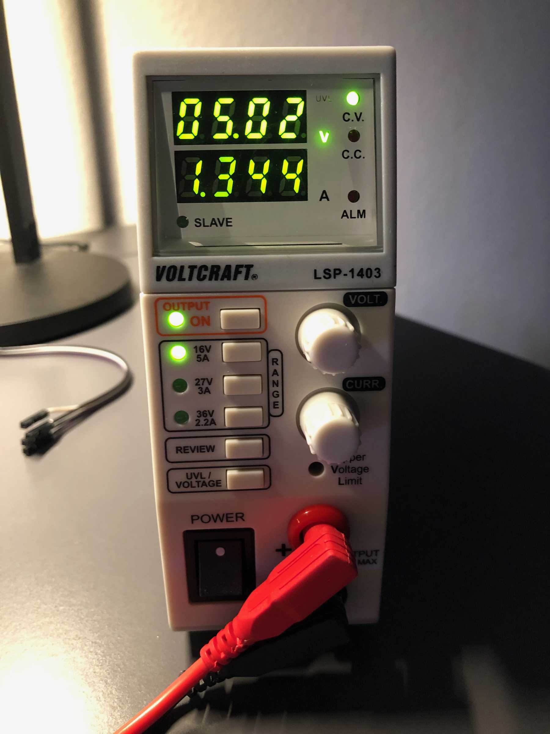
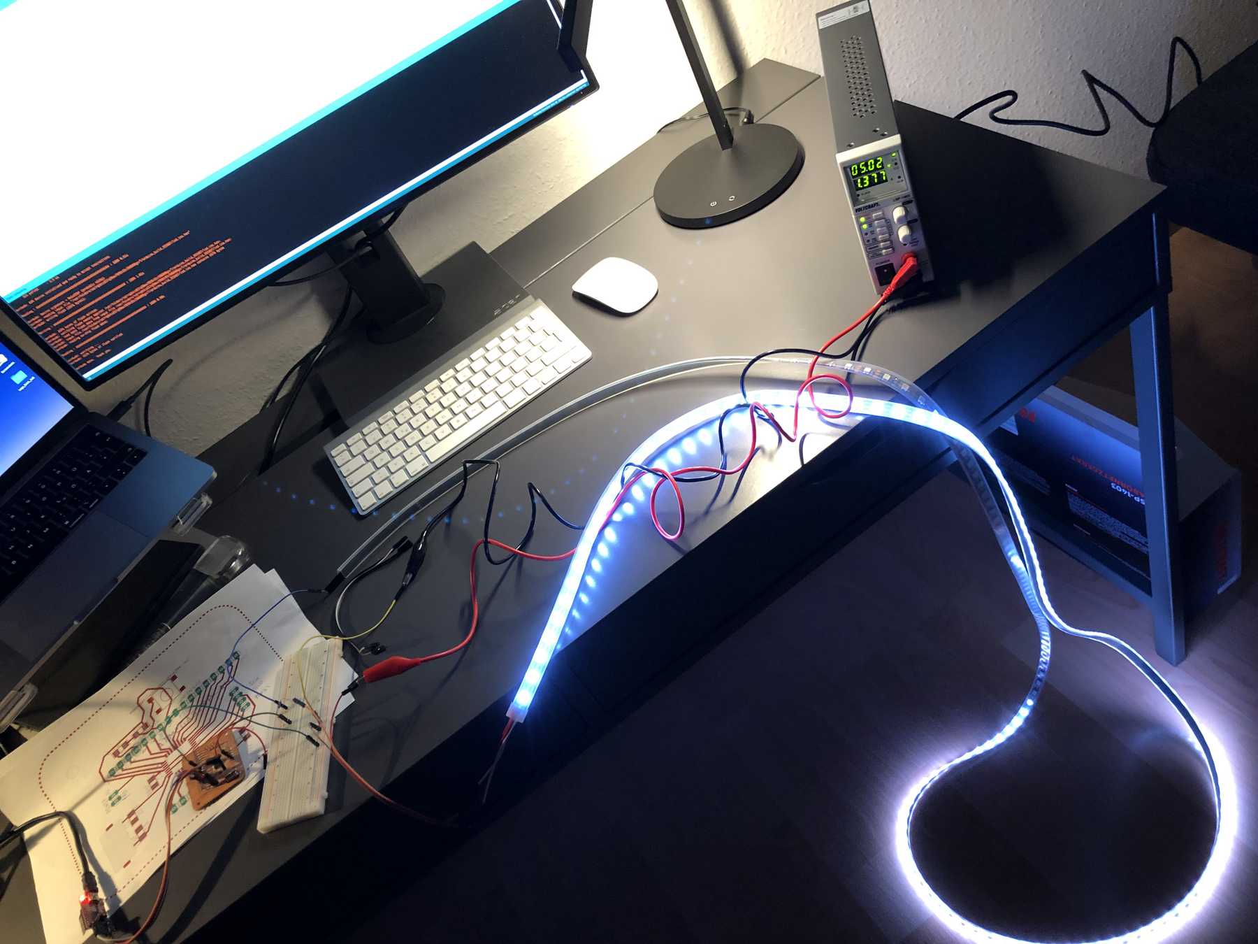
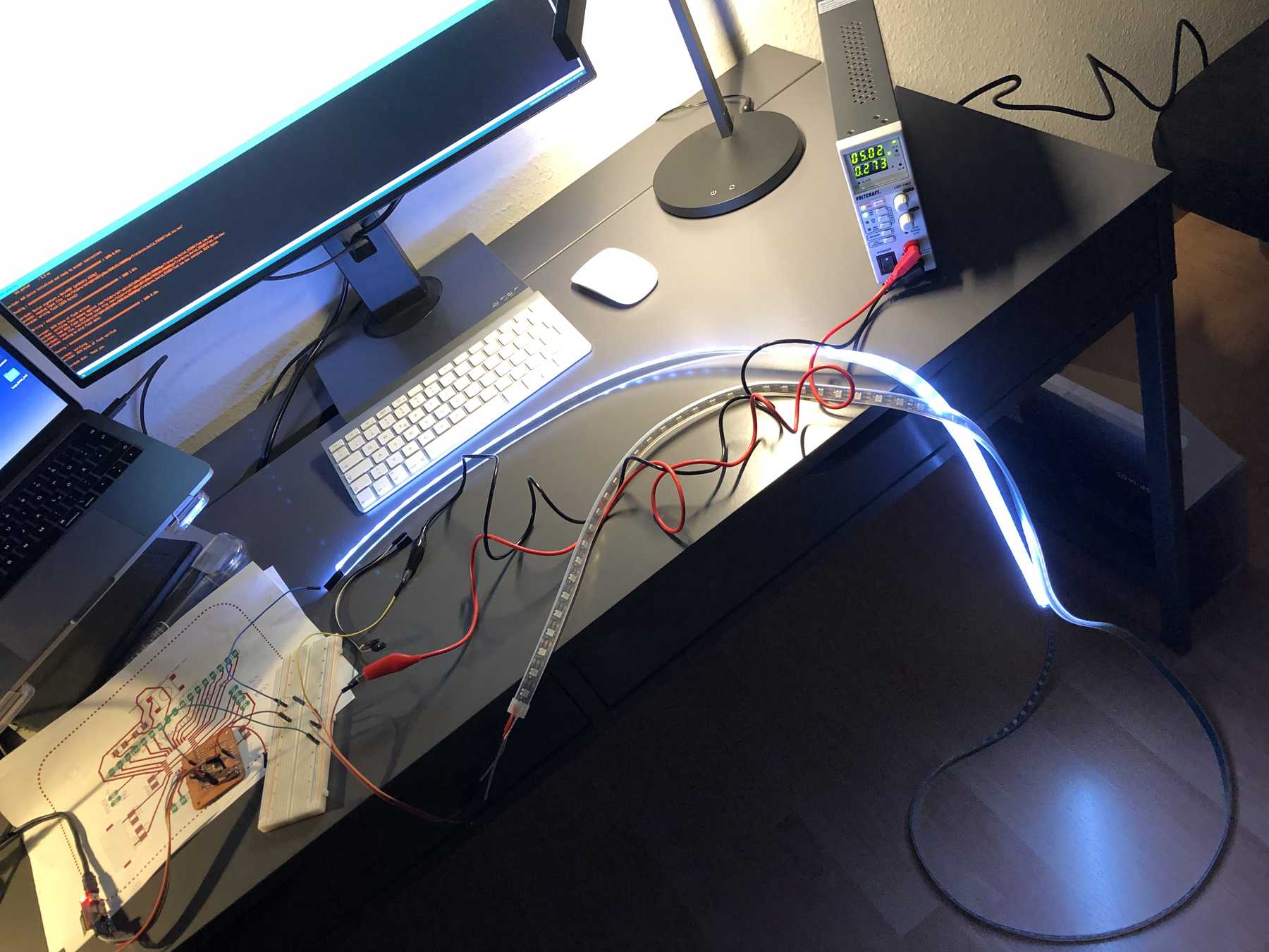
Depending on how many LEDs are illuminating, the power consumption is of course lower or higher. The variation can be seen from the video as well as from the pictures. This results in a power consumption of 0.75 W (5.02 V * 0.15 A) up to 6.9 W (5.02 V * 1.37 A).
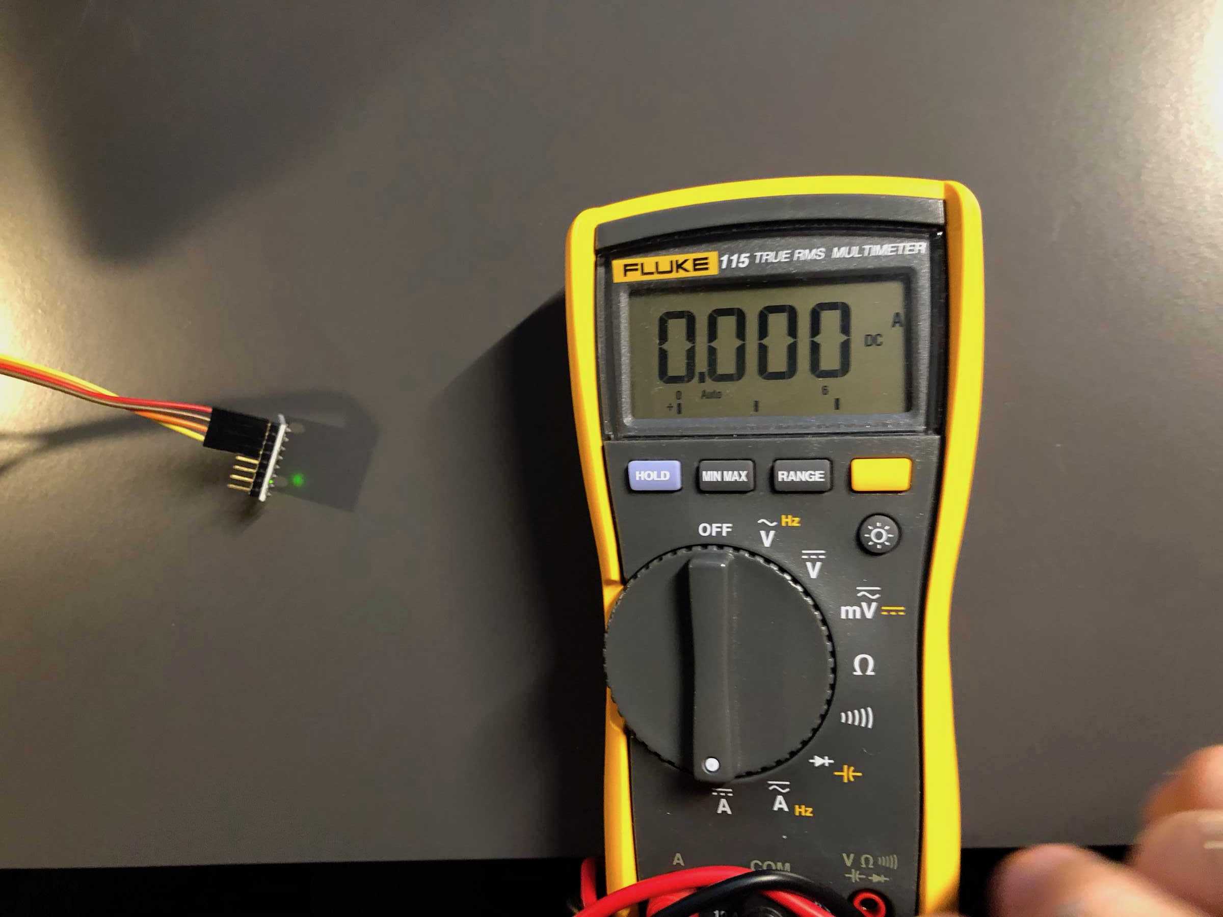
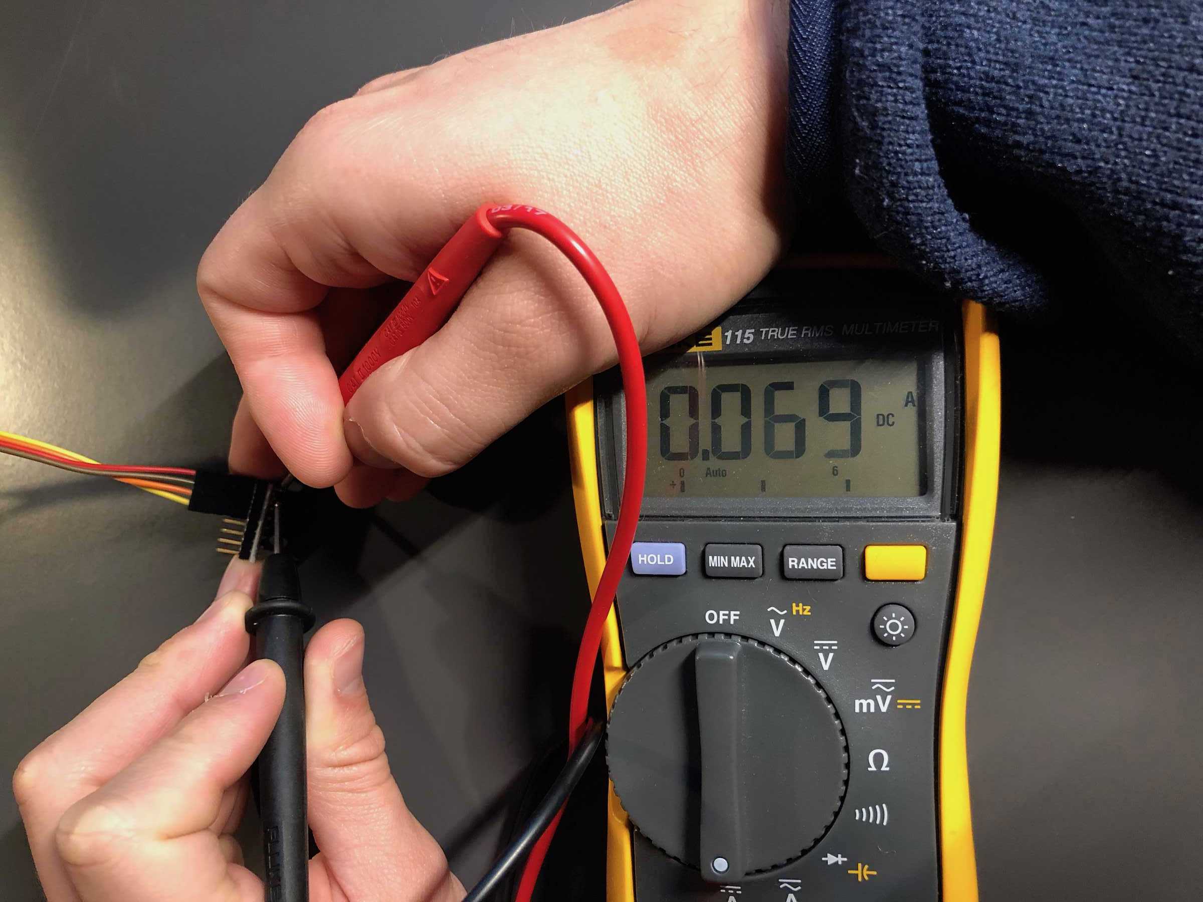
Next I measured the power consumption with a multimeter when using a gyroscope. Therefore I plugged in the plugs of the multimeter to measure the current. Then I measured one line VCC and the other line GND. By the measured value, the known applied voltage, I could calculate back on the power consumption. In this case the power consumption is 5 V * 0.069 A = 0.345 W.
Here you can download the files mentioned above:
EAGLE files of the fabduino-board