For my final project I want to make a cover for a chair.
The cover would detect if someone is sitting in the chair and when someone has been sitting for too long it will notify the person.
I have not decided what kind of notification I will do but I have a few ideas.
First would be connecting it to an app on your phone that would send notifications when a person has been sitting for too long.
Then it would be possible to do more with the app like have easy practises that are good for the back and joints.
Another idea was to have a little vibrate that would start when sitting for too long.
Then an idea I had was to have a light and it would change colour depending on how long you have been sitting for.
I think the light would be too little and might go unnoticed alone,
but I think it could be nice to add the light if I have time.
The last idea would be to have the chair connect to a sport watch or a smart watch and notify through them.
I think it would be to hard to have it connect to the watches, but it is a nice idea.
Final decision
I ended on making the chair only with light as an output and the light is also only one colour. It turns on when someone has been sitting for to long.
Process so far
In the
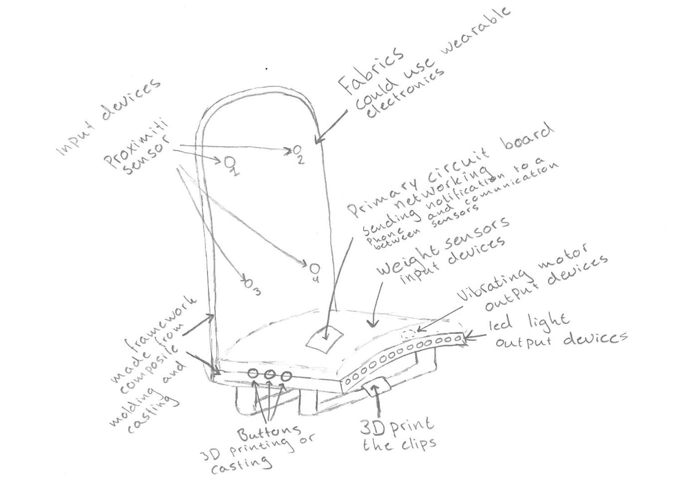
first week I started by drawing an idea of my final project.
There I talk about my thought process and have a drawing of what I wanted to make. However, the Idea has changed from then, now I would like to make it be more like a sheet to put over the cushion.
Not making a whole chair and make the cover not so big and clumsy.
I would like you to barely notice it.
In the
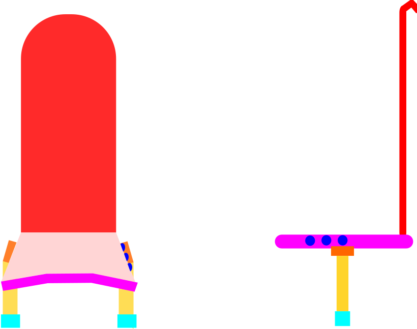
third week I drew my idea in Fusion and in Inkscape.
In that week my idea changed alot so there you can see what I started with and how my idea ended.
However the final drawing in fusion is not the best
because I whant it to be alike a sheet and having that texture was not going so well.
In the
fifth week I tried making a step response because I thought it could be a nice way to detect if someone would be sitting
and I really like the way it works so I am planning to use step response in my final project.
In the
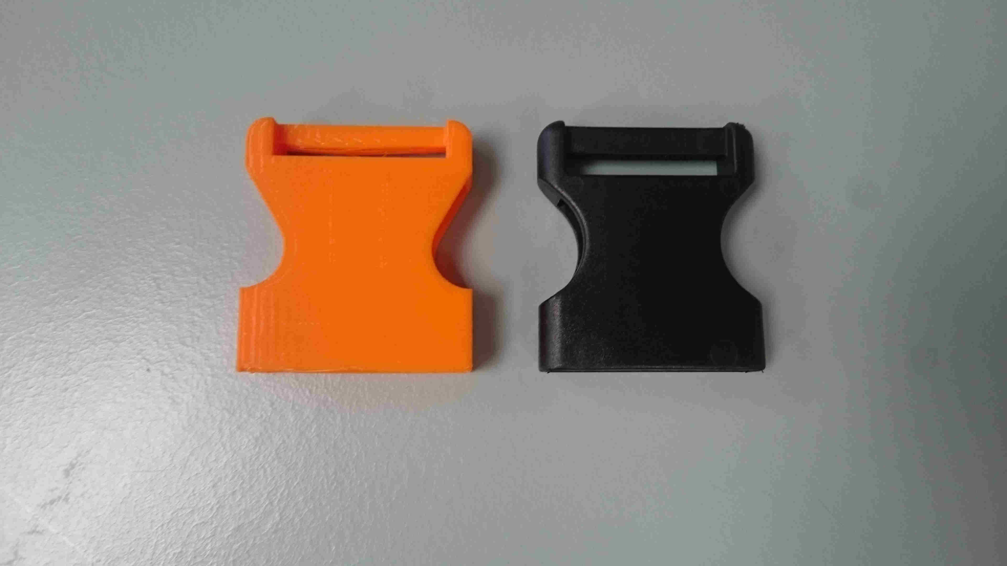
sixth week I designed the bottom part of a clip and printed it.
It was a little out of proportion so when I have time I will fix it.
I also scanned the other part of the clip and I am planning on printing that also when I have the time.
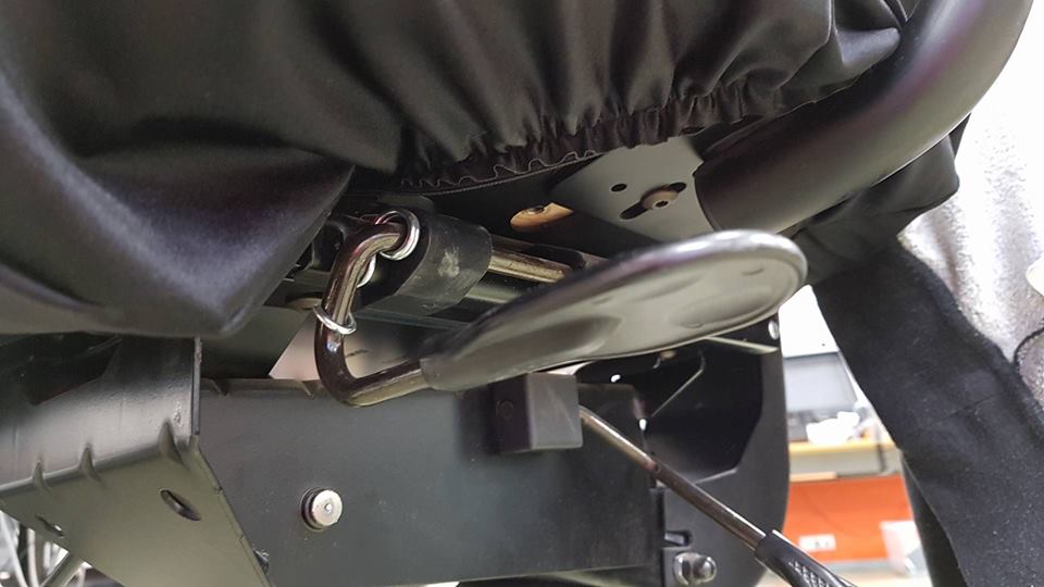
I will be using the clip as a part of my final project, I will have the cover clipped under the chair,
so it won´t be moving too much.
In
Week 10
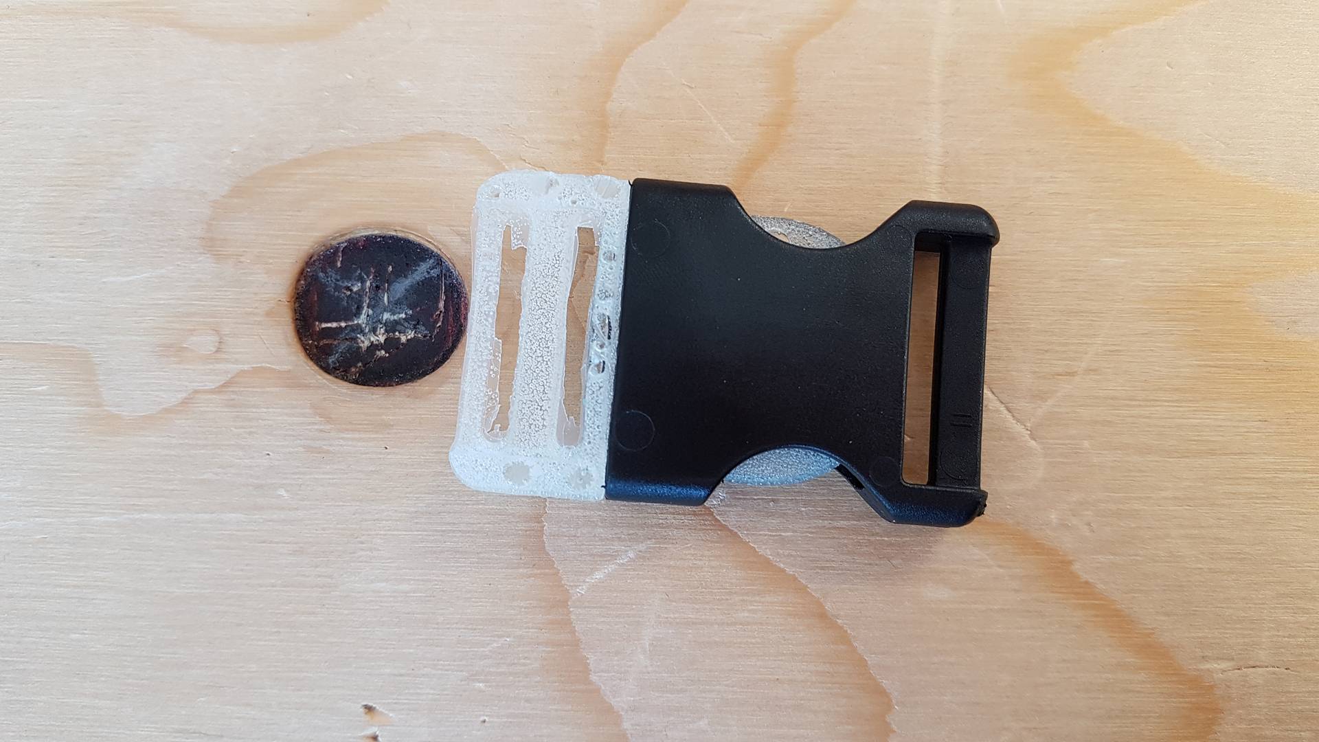
I made the other part of the clip. It worked fine with the original clip but the 3D printed one is still out of proportions so I have still have to find time to fix it.
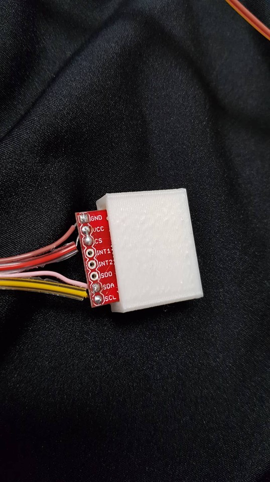
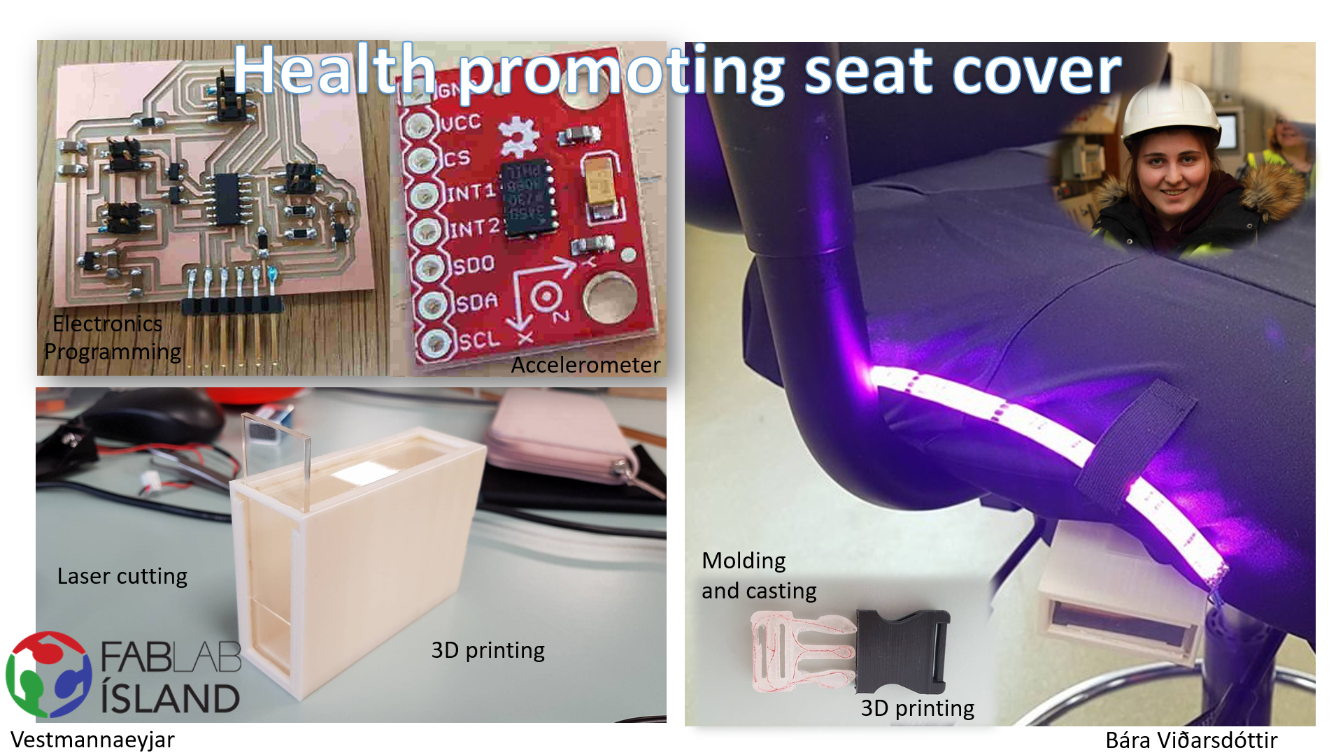
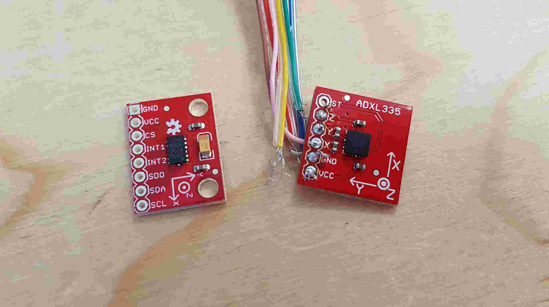
In week 12 I made a board with an accelerometer. I whant to use an accelerometer instead of the step response. I spent alot of time trying to solder one but it was not working out so now I am using the ADXL335 from sparkfun.
In week 13 I added an LED strip to the accelerometer. I have not finished programing it but when I do I will put it on here.
I bought the ADXL345 and I am planning to use it for the final project instead of the ADXL335.
I decided to connect the ADXL345 to an arduino and check if I could get it to work. I followed
these instructions and it worked.
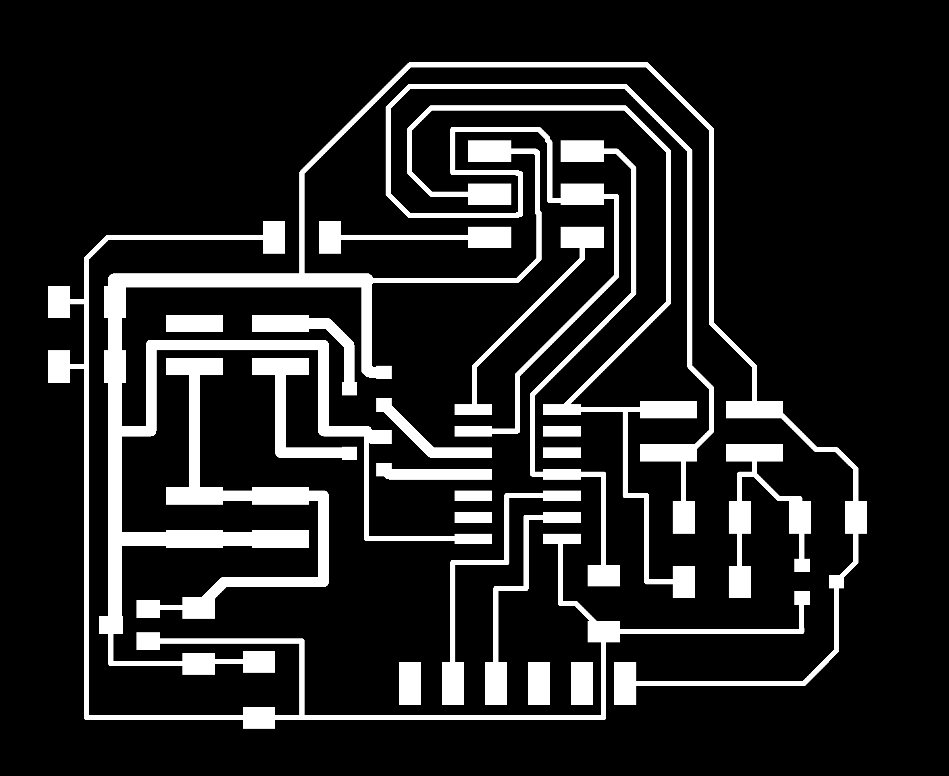
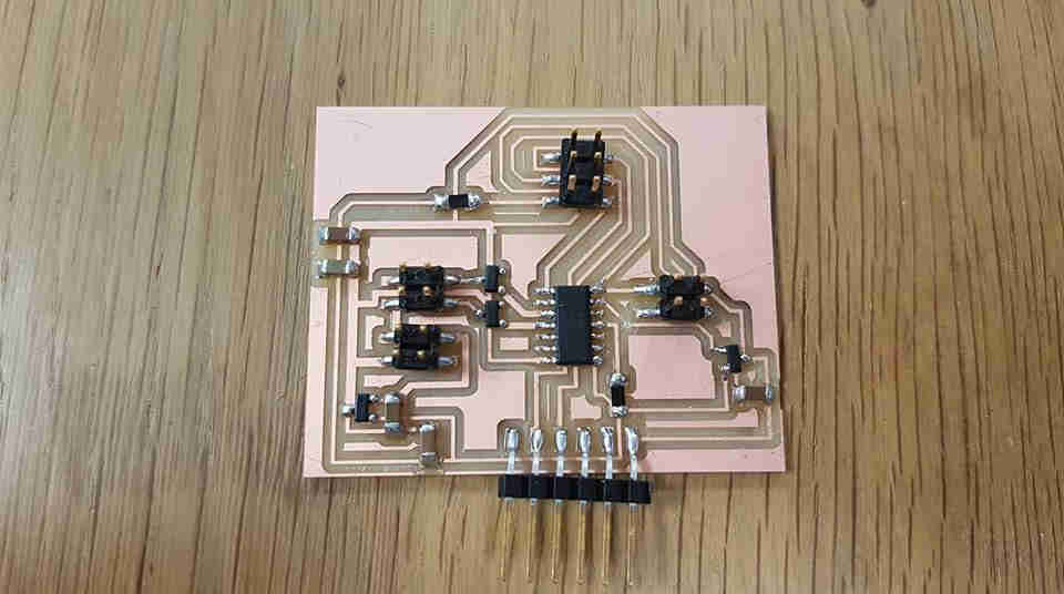
I redrew the board so I could use the ADXL345 with it and I also added a 4 pin header to connect battery to it. I got some help from Bas and then I milled it and soldered.
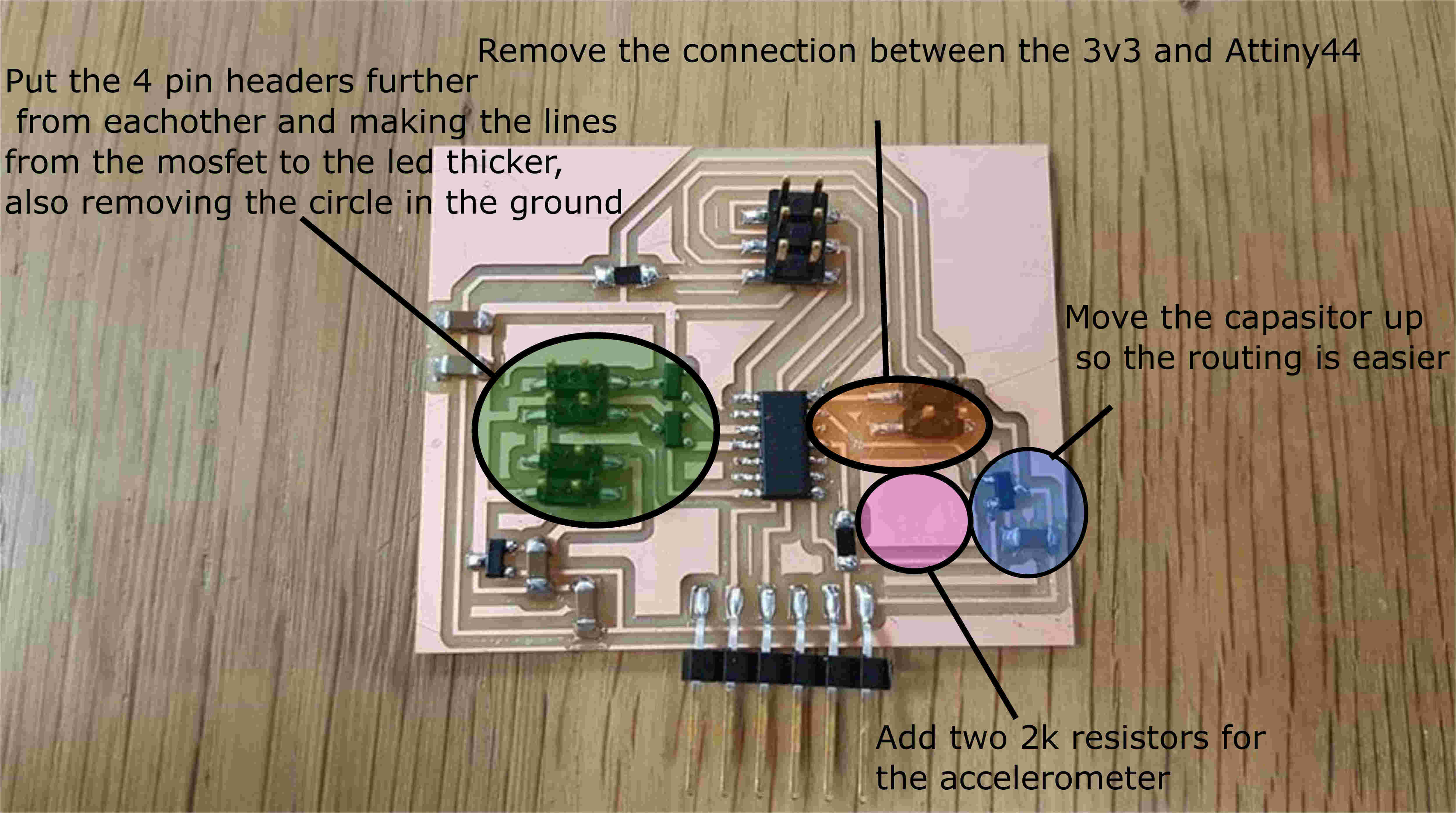
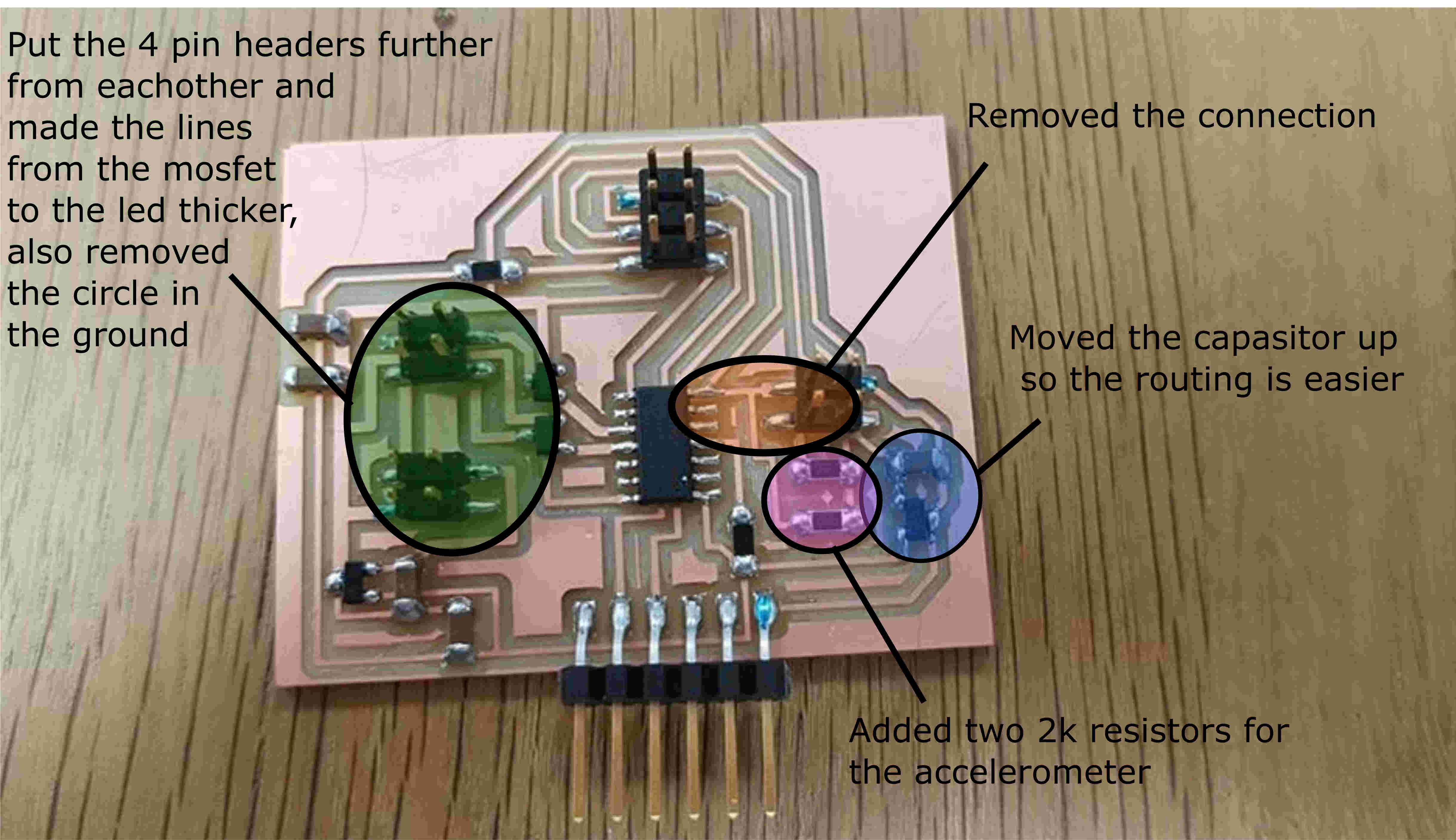
I had a few problems that I needed to fix. I made the lines thicker for the LED so all the current can go through, I had already done some on the other board but I had to do a few more. I also removed a connection from one GND to another because it made a circle. I removed the line between 3v3 and the Attiny. I moved one capacitor further up because it made routing easier and added two 2k resistor.
I then programed the board using arduino. I got a lot of help from Bas since this is the part I am worst at. We found an example code online that we used and then we also used Niels code for the hello echo so we would not need to use the Softwareserial library because it is so big. We also used the USIWire library to talk to the board. We got the code to work and it does talk to the accel, I did have a problem where the only reading I could get from the board was a zero but then with some help from Bas we realized I need to unplug the ISP and restart the power so it will start reading. You can see some documentation about this in my Networking week.
I decided to check if the LED-strip is working properly so I found an example code that uses millis because that is what I will be using in the code for my final project. You can read more about that in my output week
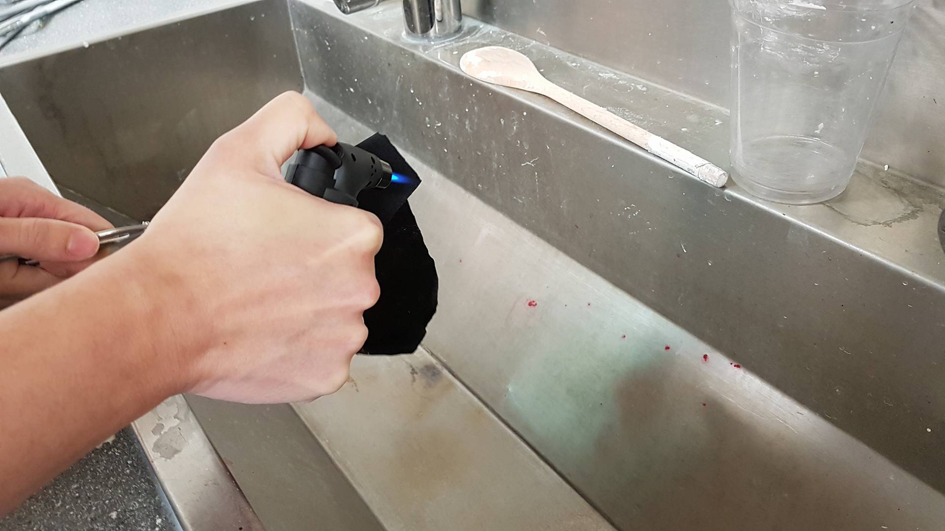
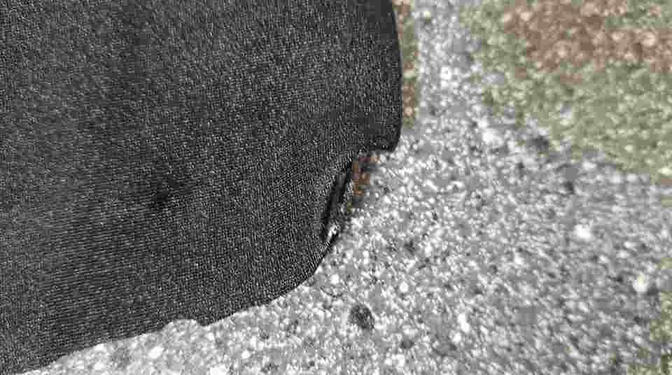
In Reykjavík Linda found som elestic fabric that I can use for my final project. My plan is to lasercut the fabric so Linda did a burn test with me. I have never done a burn test before so this was exciting. In some fabrics there is plastic called TPU and it is not good for the lasercutter or for your health. A burn test is done by taking a fabric and burning it, prefurably with copper. If the flame is orange and with light smoke the fabric is save to use but if the flame is green the fabric containse TPU and you can not use it. The fabric linda gave me did have an orange flame so I can cut it in the lasercutter. However there is some shrinkage and the ends harden so we will have to see if we can work with that.
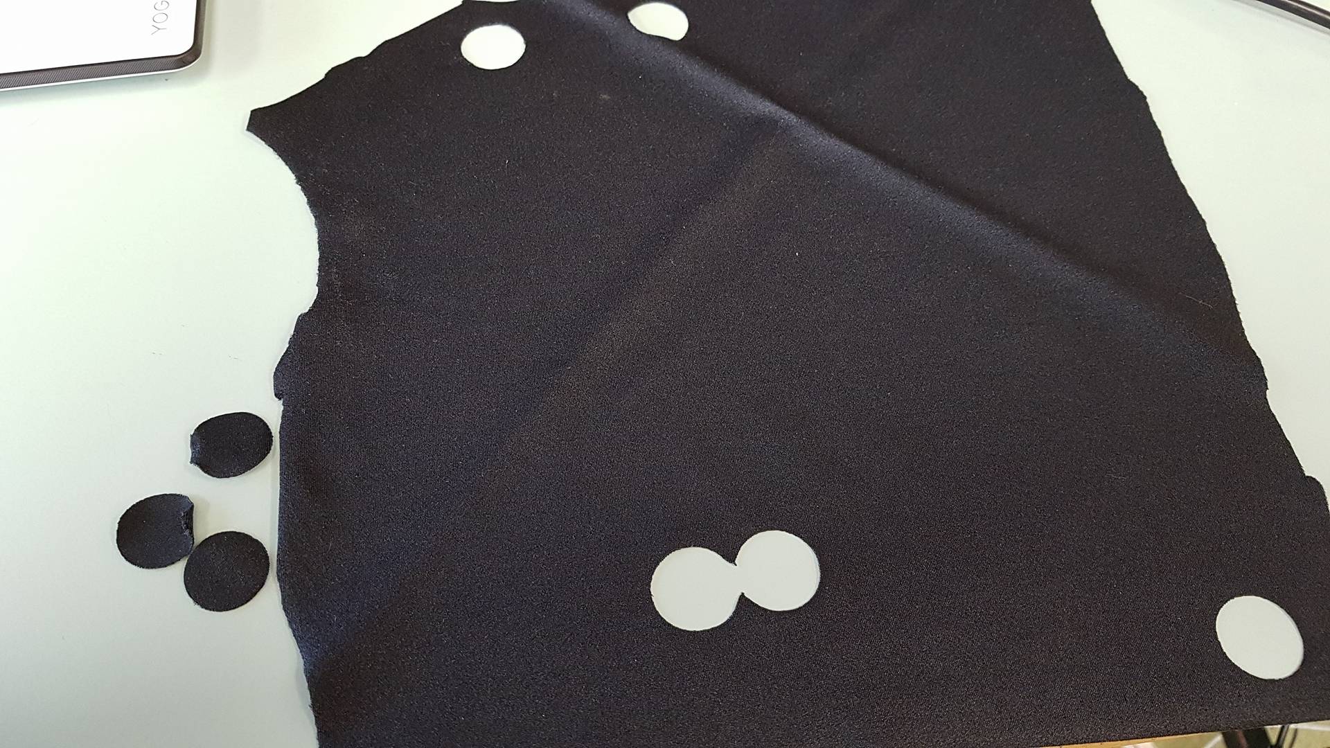
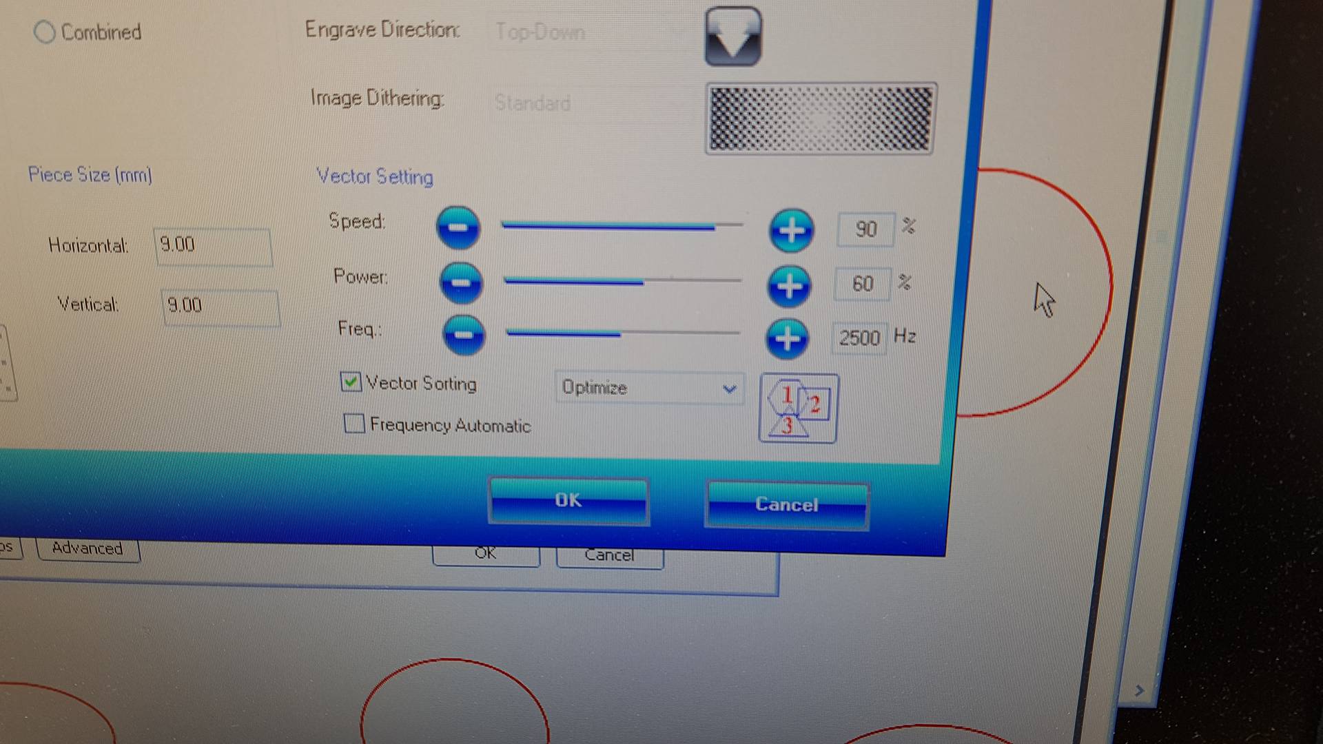
I tested lasercutting the fabric by cutting a small circle in the fabric the outcome was nice. I used the same settings as I used in the Wildcard week.
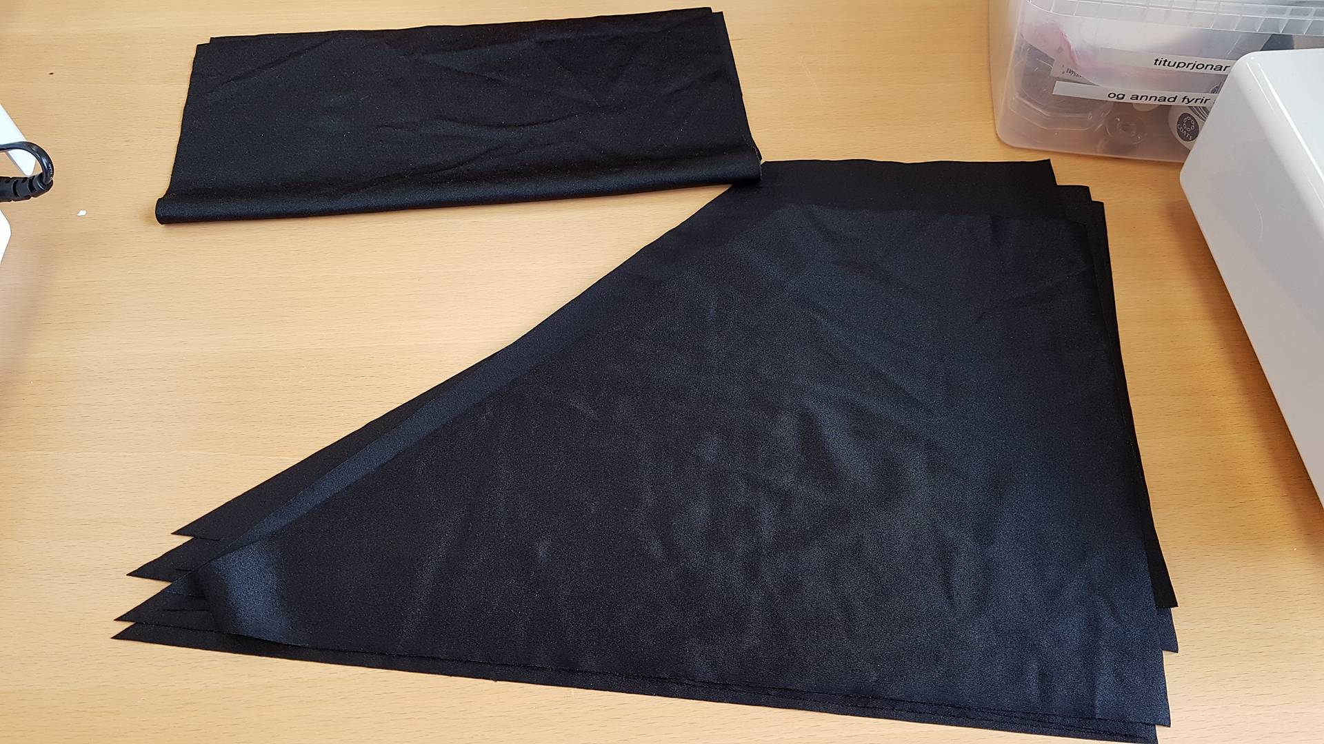
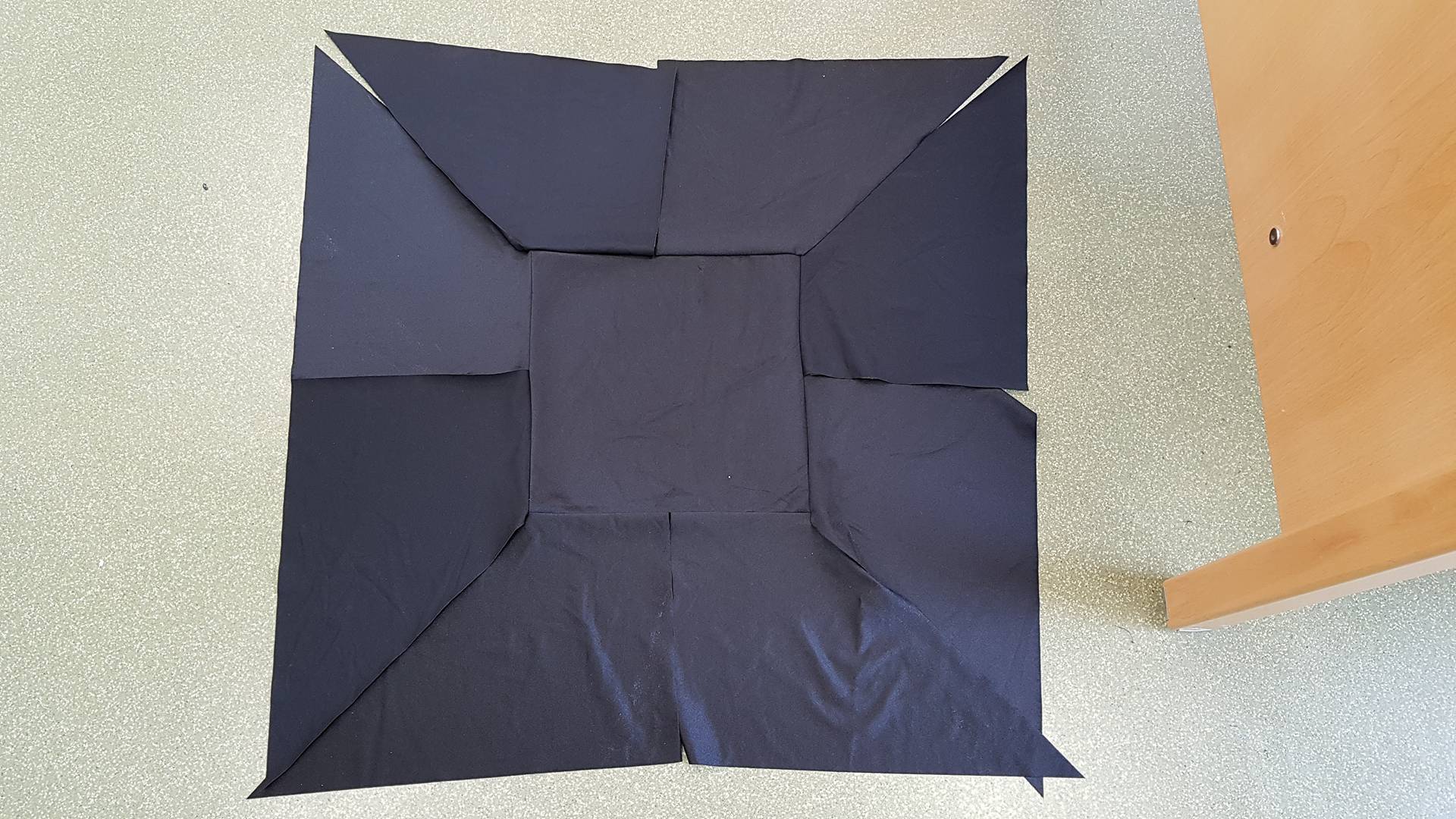
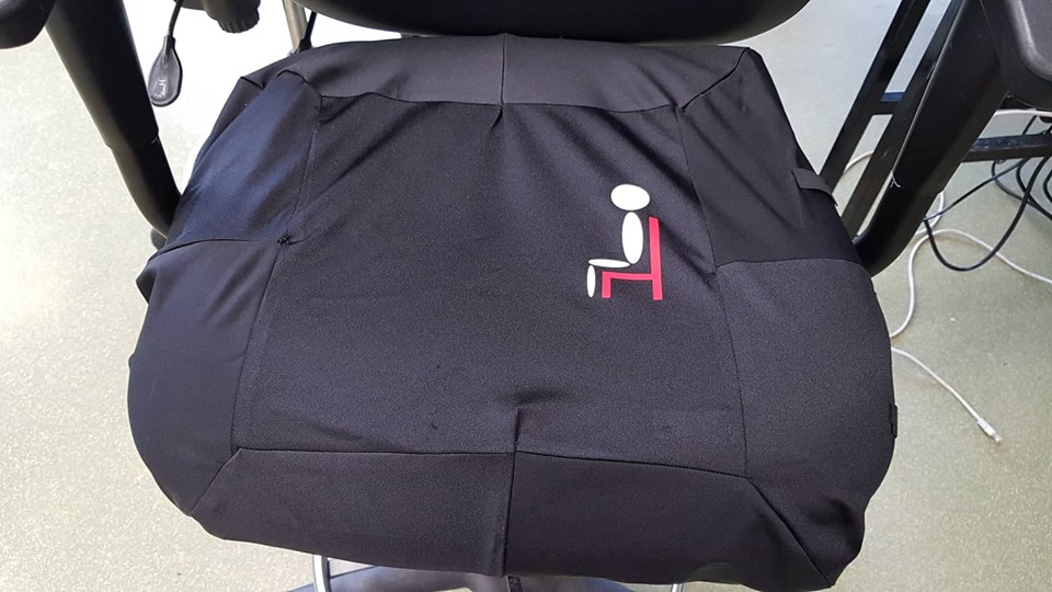
Then I design the cover in inkscape and cut it out in the lasercutter. The outcone was good. I made 8 of the triangle things.
Then I made one of the square thing.
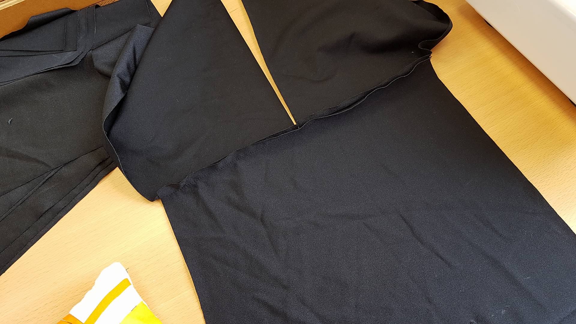
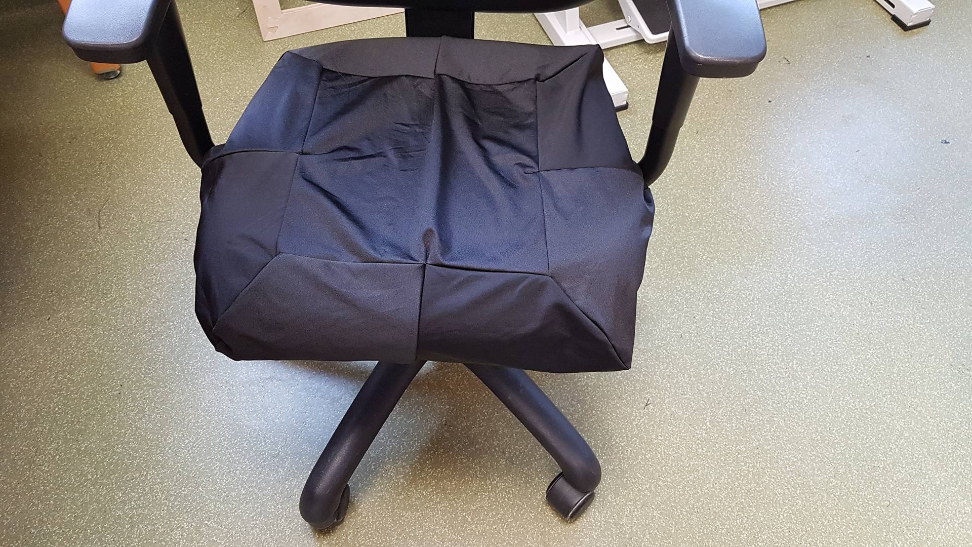
Then I spent some time sewing it. I messed up two times where I turned it the wrong way but it did not take to long to fix. Now That I have sewed all the parts together I only have to add an elestic band onn the bottom to keep it better in place.
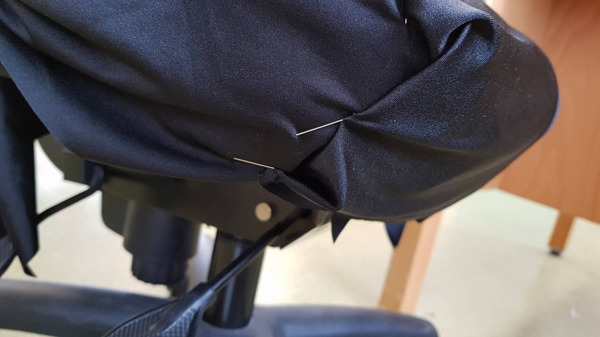
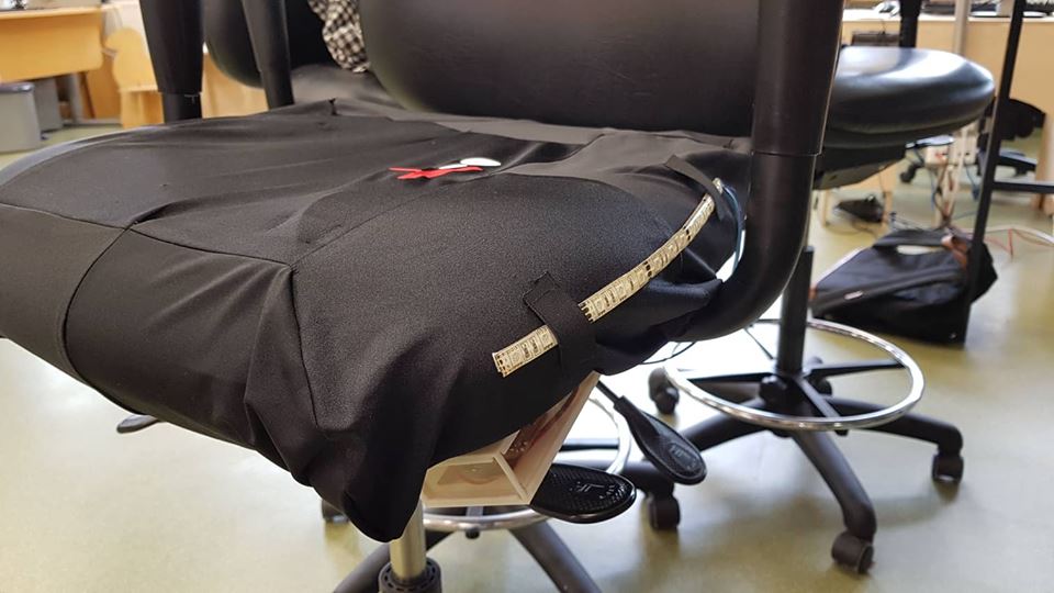
I put the elestic part on the bottom but I also added some elestic to keep the LED and the accelerometer in place.
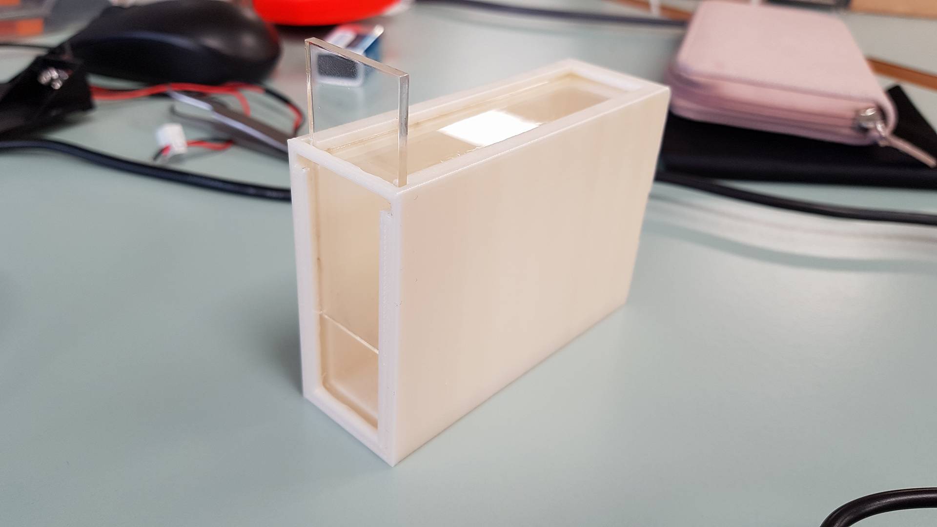
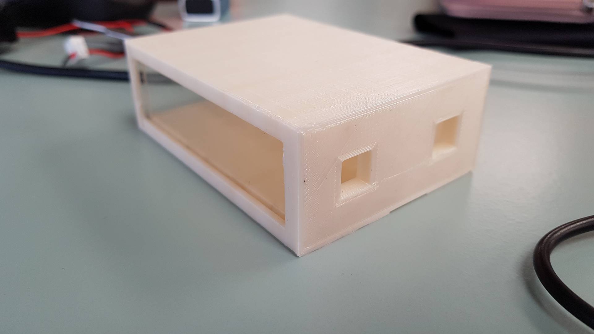
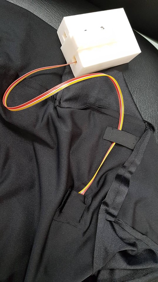
I made a box that I will put my circuit board and battery in. I designed some of it in Fusion and some of it in Inkscape. Then I 3D printed the box and lasercut two of the sides that slide in and out of it. On the back I also have 2 holes so I can connect the LED and the Accelerometer through them. It lookes really nice and everything fits in but I forgot to make a way to make it stick to the cover so I have to find some way to fix that.
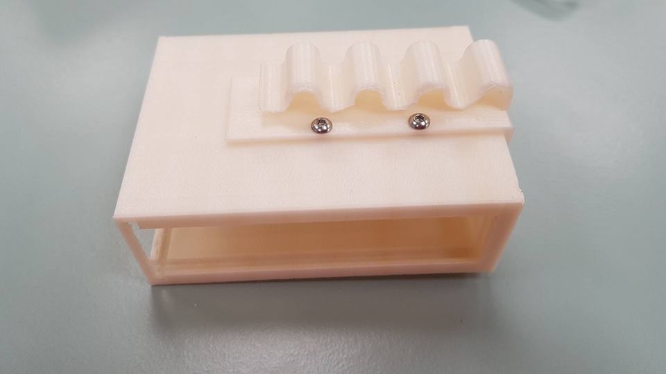
I designed a part to add to the box. I designed it in Fusion and 3D printed it. The outcome is pretty nice but it is a little loose but still workes.
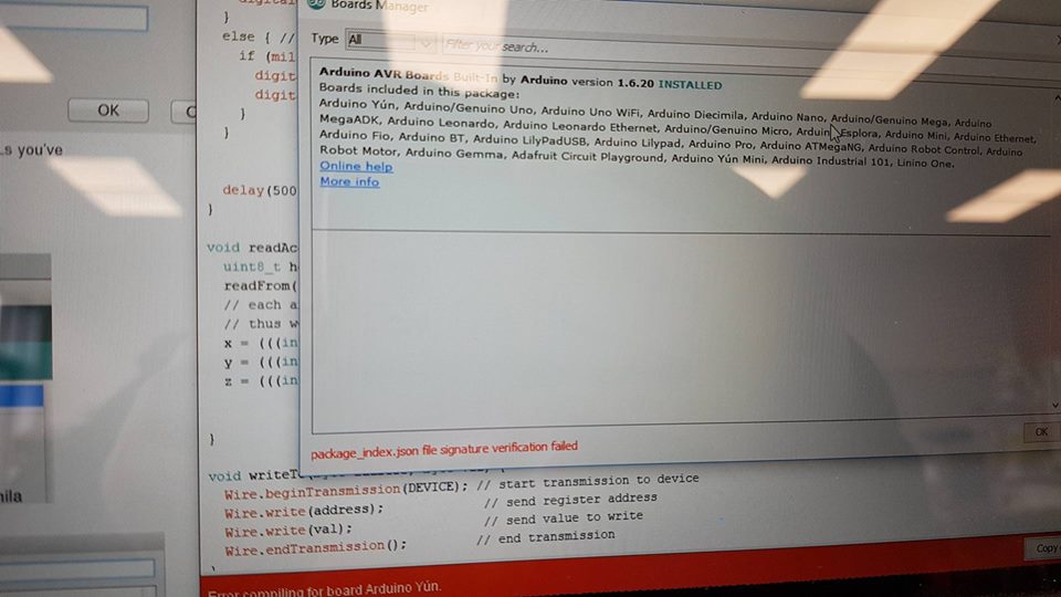
I finally finished my code but at the same time arduino stopped working properly on my computer. It would not allow me to program the attiny. I spent so much time trying to fix that until we finally found the solution, we had to go into arduino and delete the board and downlod it again.
The accelerometer is also not working to well because it keeps freezing but I am still working on fixing that. I think it has to be put in a better protective cover so I 3D printed one to test out if that is the problem. I have designed a tiny box around the accelerometer that I 3D printed, Now it is working again.
I also finished making everything more puttogether under the cover so the cables dont go all over the place and the accelerometer stays in place. To make it I just cut a square out of the fabric and sew it on the bottom side of the cover. I also have a little strip out of a tie that I just cut in the size I wanted and sew on there. The same for the strips thamt hold the LED in place.
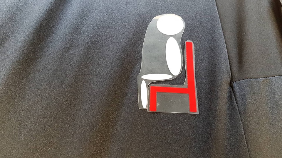
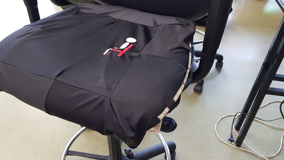
Then I finished by making a little logo with the vinil cutter to put over some of the seams that I did not want to be showing to much.
Now my final project is up and running.

_LI.jpg)
.png)
.png)