Input Devices
Week 10
2nd - 8th April 2014

I was very curious about the step response sensing technique - thus I've built this cirtcuit to give it a try. Everything worked without a hitch, but it seemed a bit too dependent on proximity of conductive objects in the vicinity. Therefore I decided that it's not an optimal solution for my project.
Step response technique is extremely versatile, as it does not require any special sensors. Just two electrodes made from any conductive material are enough. Absence of specialised transducers is compensated with thoughtful mechanical of the elctrodes and computational power. This technique can allow for the measurement of distance, presence of other objects, pressure, acceleration, tilt, humidity, touch, etc.
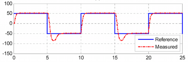 The technique relies on emitting very fast rectangular electromagnetic pulses into the environment from one electrode (Tx / reference / blue) and measuring their distortion on arrival to the second electrode (Rx / measured / red).
After milling / populating / programming the board from Neil's examples, I realized that this technique might cause problems in my project, as different pairs of Tx/Rx sensors will be moving closer and further to each other and might interfere with each other's measurements. This led me to look for a more robust solution.
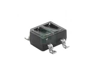

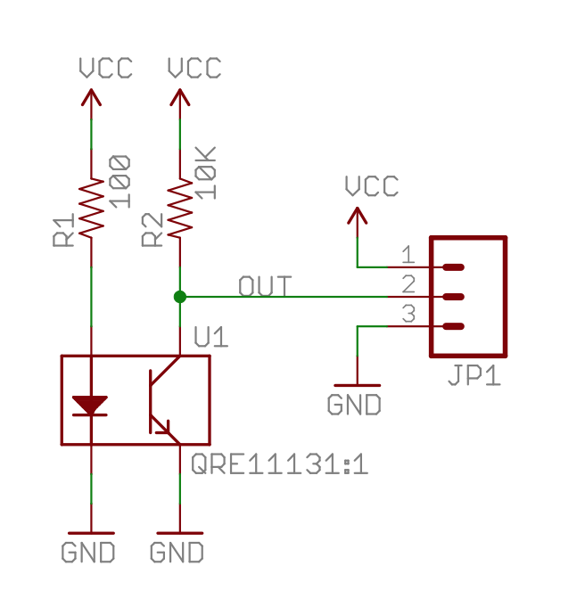
The next solution I tried was infrared reflective sensing. Technique popular in hobby robotics for measuring the position of a robot's wheel or for line follower robots. For this I used QRE1113 IR reflective sensor.
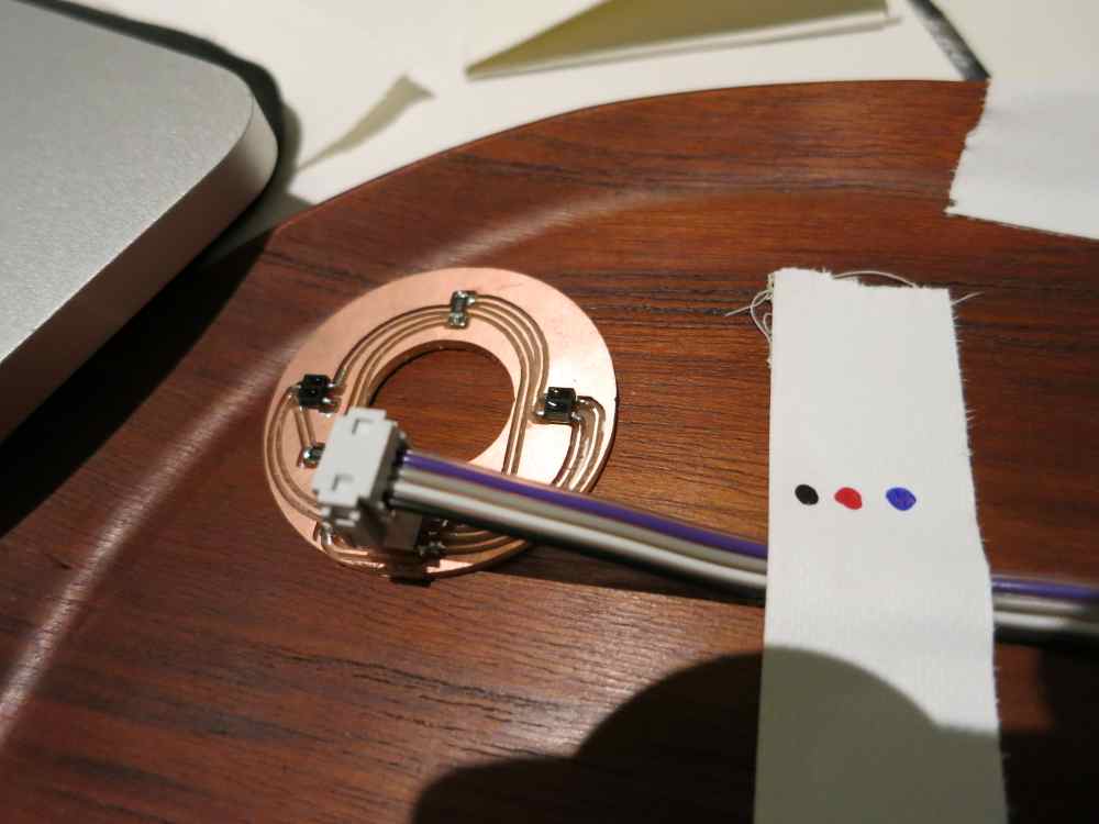
In order to to measure absolute position of the modules relative to each other I decided to use two such sensors with an offset. The easy part of design / mill / populate cycle for the sensor breakout board was complete in half a day. The measurement / programming / debugging phase proved to be much more difficult. And after several attempts at getting reliable results, I resorted to the backup plan with the mechanical rotary encoder.
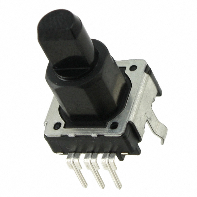
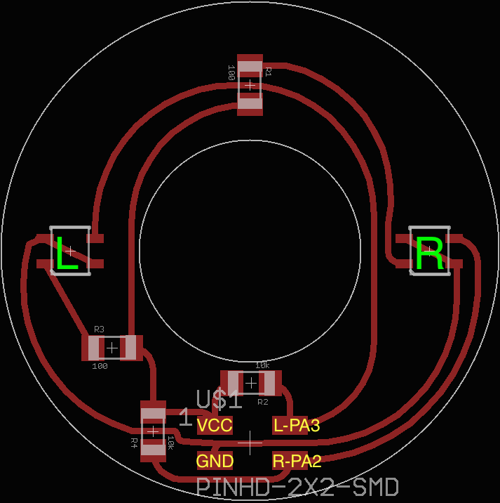
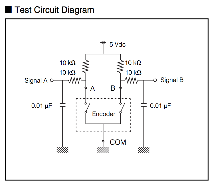 Primary criteria in chosing the encoder for my project was price. The complete Zmeika puzzle ultimately consists of 24 or 36 joints - this is the amount of position sensing devices that contribute to the overall project cost. This panasonic P12335-ND encoder is priced just under 70c per piece and provides 24 pulses per rotation. Paired with the debounce circuit provided in the datasheet, hooking it up to the ATtiny was a breeze. By the time I was working on this part, I already had no access to the Modela mill, so the filter networks of 4 resistors and 2 capacitors were built from through-hole components and soldered directly to the encoders.
The last major challenge with getting the position sensing to work properly was to hook up the encoder to the interrupt pins on the ATtiny44. Original APA is designed in such a way that the host machine requests a value from the APA node by sending it a message, and then receiving the value back. This approach wouldn't work in my case.
Imagine one full twist (24 pulses) happens in 1/10th of a second. This means that we have to poll every node at least 240 times a second. And in total - 24 * 240 * 2 = 19200 APA messages have to be sent every second (requests and responses).
An empty APA message is already 4 bytes long({^|}). 4 * 8 * 19200 = 614400 bits per second. This way we have already used pretty much all of our serial port bandwidth without even transporting any data.
The solution to this would be to use interrupt pins on the ATtiny44 and to make the MCU send APA messages back to the host whenever a change occurs. Original APA design doesn't have this functionality, particularly because it uses the address received with the request message to send back the reply. I had to make a hack which pings every node and stores the address of every node at the power up phase. You can see it in action in this video. Or on the final project documentation page.
Design files for this week are:
