


Final project presentations
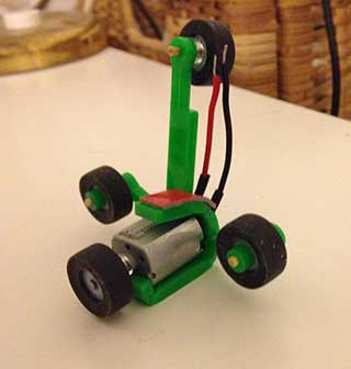
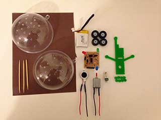
For my final project i started with designing a mount that will hold all the components i have together.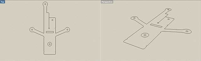
I cut it with the lesser cuter.
You can download the mount file.
After that I banded perspex with the heat gun at the lines I marked.
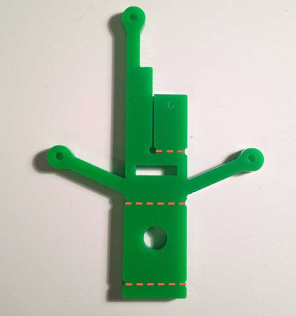
You need to bend the perspex in the right size for it to hold the motor, wheels, board and battery.
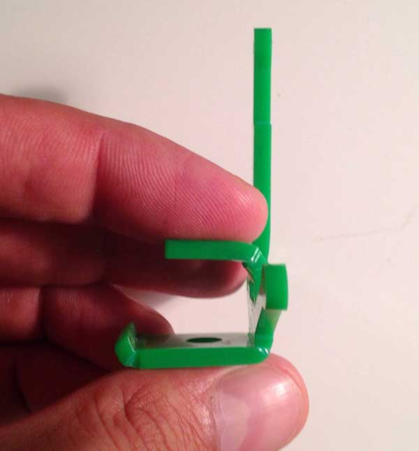
Remember that the top piece should be bent to around 70 degrees. That way you inshor that nothing touches the wheels.
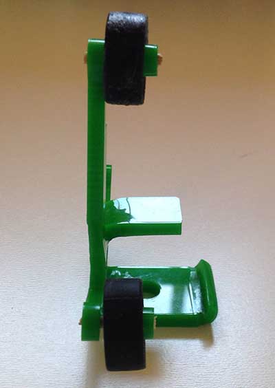
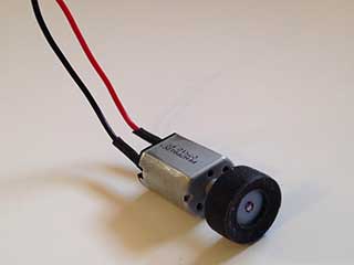
I 3D printed the wheels, using soft and hard material.
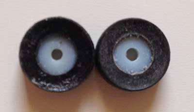
You can download the wheels file (you will need 4).
Now stick toothpicks in the wheel holders, then insert the wheels and the stopper.
You can download the stopper files(you will need 4).
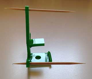
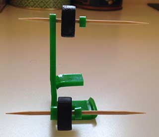
Once you place the parts in place you can cut off the excess touth pick.
Now you need to cover the motor head with wire insulation.
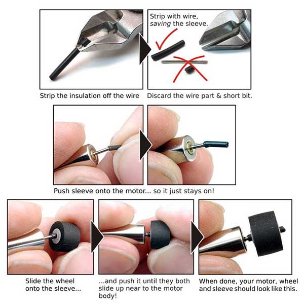
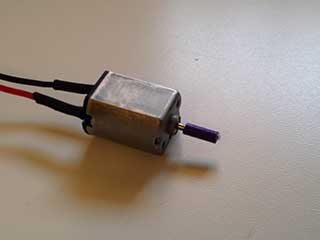
Test the amount you bent fits in the ball, and make adjustments.
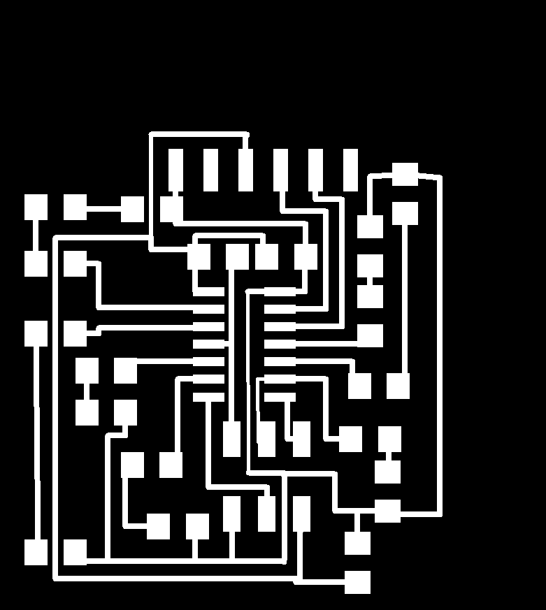
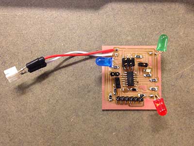
The board I designedinterior / trace using eagle with all the parts and sensors I needed .

You can download the board, schematics.
The components you need are :
| Component | Qty | ATtiny 44 | 1 | mosfet n-ch | 1 | 100om resistor | 2 | 499om resistor | 4 | capacitor 1uF | 1 | 10kom resistors | 1 | leds | 4 | motor | 1 | piezo sensor | 1 | speaker | 1 | lithum battery 3.7v | 1 |
After you finish soldering burn the Arduino code on your board.
// - LEAD MELODY
int cycVec[] = {                   1136,1136 ,1073, 1073,     1276, 1276,	1073,	 1136, 	1136, 1136, 1073, 1073,	1701,	 1805, 1136, 1805,     1515,	1515,	1433,	1433,	  1701, 1701, 1433,1515,   1136, 1136, 1073, 1073,    1276, 1276, 1073, 1136,1276,1136};
int noteDurations [] = {  440	,220	,466	, 466	,       392, 392, 233, 1320, 440	,220, 466, 466, 294, 277,	220, 554, 330, 165,            349, 349, 294, 294,	   174, 990	, 440, 220,       466, 466, 392, 392,           233, 220, 196, 440, 220, 220};
int noteLength = 34;
int delayInBetween = 3;
int BPS = 10;

// this constant won't change:
const int piezoPin = 2;    // the pin that the piezo is attached to
const int motorPin = 3;       // the pin that the motor is attached to

long motorTime = 0;
int piezoState = 0;


  int ledOne= 10;
  int ledTwo= 9;
  int ledThree= 4;

void setup() {
  pinMode(piezoPin, INPUT);  // initialize the button pin as a input:
  pinMode(motorPin, OUTPUT);
 pinMode(ledOne, OUTPUT);
 pinMode(ledTwo, OUTPUT);
 pinMode(ledThree, OUTPUT);

  // initialize serial communication:


    int speaker =7;
  pinMode(speaker, OUTPUT);
  for (int m=0;m< noteLength;m++) {
    noteDurations[m] = (noteDurations[m])/BPS;
    //pauseDuration[k] = pauseDuration[k]*1000;
  }
}


void loop() {

  //  piezoState = digitalRead(piezoPin);  // read the pushbutton i
  //  Serial.println(piezoState);
  int speaker =7;
  int temp;
  int cycNum;
  int cyc;
  if ( motorTime == 0 ) {
    if ( detectMovement() ) {

      digitalWrite(motorPin, HIGH);
     delay(1000);
      digitalWrite(motorPin, LOW);
     delay(200);
     digitalWrite(ledOne, HIGH);
   delay (500);
      digitalWrite(ledTwo, HIGH);
      delay(500);
       digitalWrite(ledThree, HIGH);
       delay (500);
             digitalWrite(speaker, LOW);
      digitalWrite(ledOne, LOW);
      digitalWrite(ledTwo, LOW);
       digitalWrite(ledThree,LOW);

        for (int thisNote = 0; thisNote < noteLength; thisNote++) {

    for (int i=0;i< noteDurations[thisNote];i++) {
      digitalWrite(speaker, HIGH);
     digitalWrite(ledOne, HIGH);
      digitalWrite(ledTwo, HIGH);
       digitalWrite(ledThree, HIGH);
      delayMicroseconds(cycVec[thisNote]);
      digitalWrite(speaker, LOW);
      digitalWrite(ledOne, LOW);
      digitalWrite(ledTwo, LOW);
       digitalWrite(ledThree,LOW);
      delayMicroseconds(cycVec[thisNote]);
    }

  }

    }
  }
  else {
    if ( (millis()-motorTime)>10000 ) {
      motorTime = 0;
      digitalWrite(motorPin, LOW);
     // startPlayback(sample, sizeof(sample));
    }
  }


}
You can download thecode files.Now put the motor in its place (if you bend the perspex correctly you should hear a click sound as you place the motor, that will put the motor in place and prevent it from moving).
Glue the battery to the top bent piece of the mount.
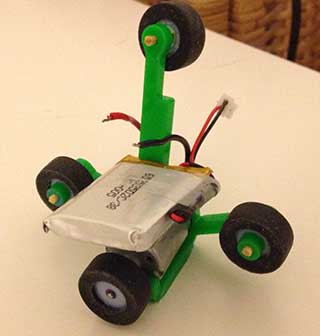
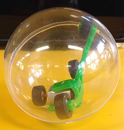
I tested the mount handling inside the ball, by connecting the motor to the battery and closing it in the ball.
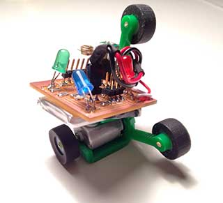
Now connect the board to the battery and test it.
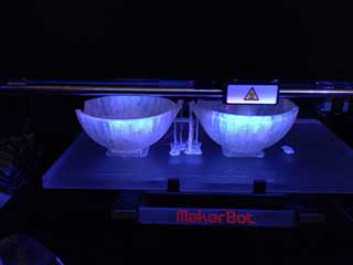
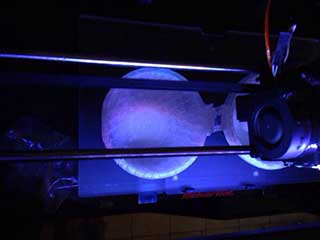
For the ball I designed a couple of balls using rhino and solid works and print them in 3D printer.
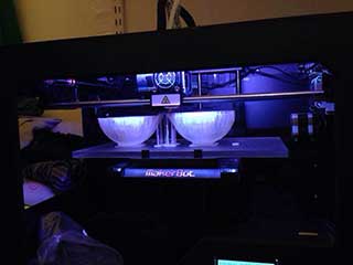

You can download the ball file.
But I had problems with getting a perfect round and smooth surfaces for it to work, (it takes 4 to 6 hours to print and costs around 1$).
Its just cheaper to buy a 0.25 to 0.75c perfect round clear ball at an art store.
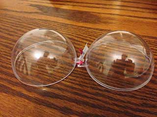
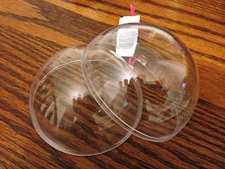
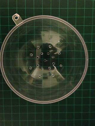
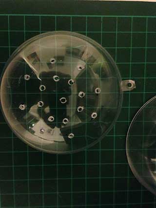
I drilled small holes for the sounds to get out (remember that you need to be really gentle when you drill, if you use to make pressure the ball will krack).
I cut off the excess plastic pins from the ball, for it to be smother I sending payper.
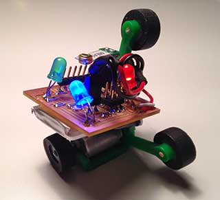
Now connect all the parts together.
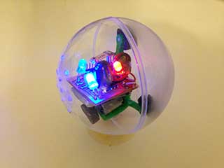
Test run.
Success.
Video of final presentation.
If you have questions or made improvements don't hesitate to contact me at: omerayal(at)gmail(dot com)