


Networking and communications
This week we had to build a wired or wireless network with at least two nodes.I decided to start with the hallo bus serial.
First I downloaded the bridge. traces and interior, (you can use this board file to know what components you need to solder).
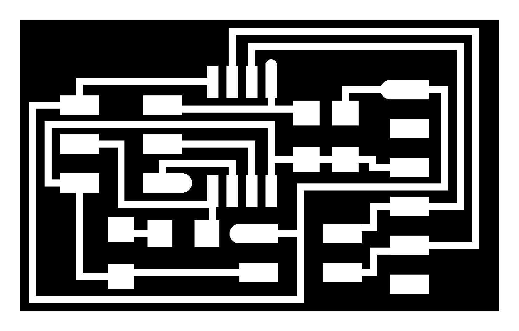
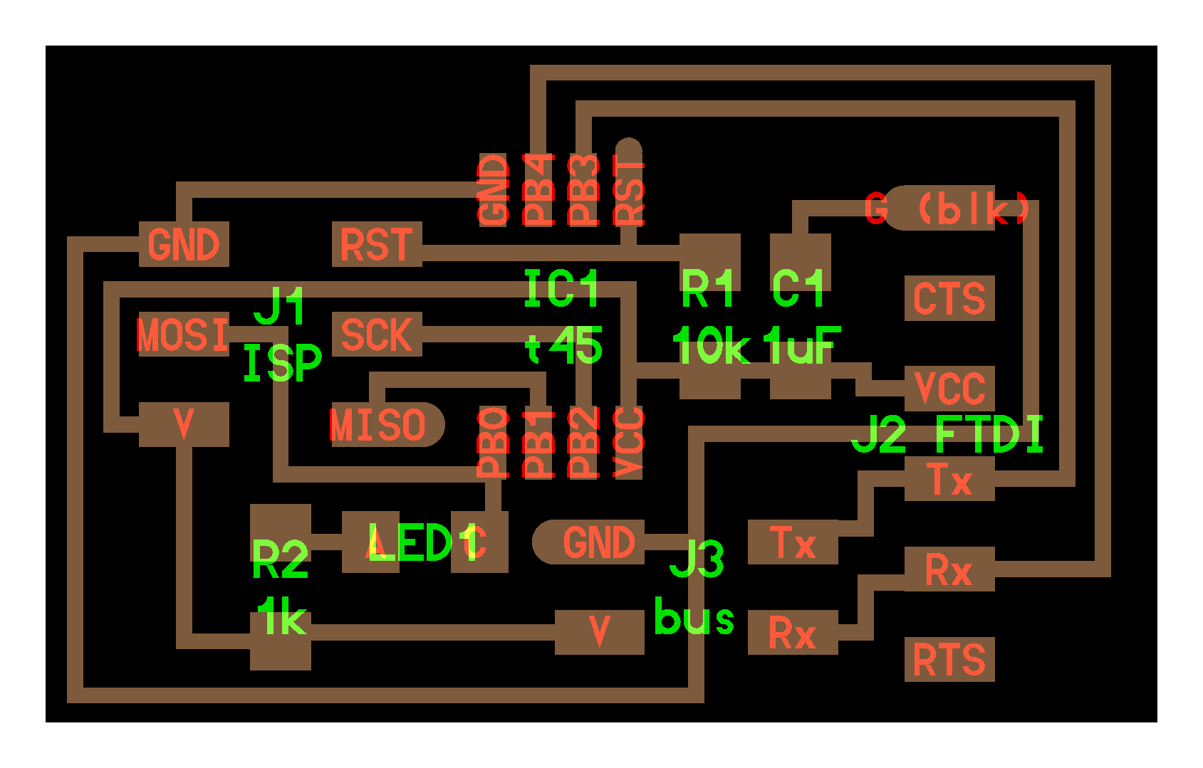
After that I downloaded the node traces and interior, (you can use this board file to know what components you need to solder).
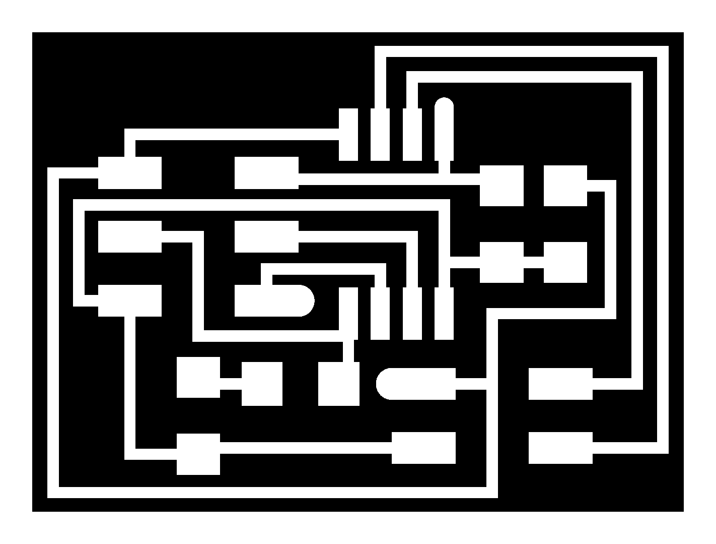
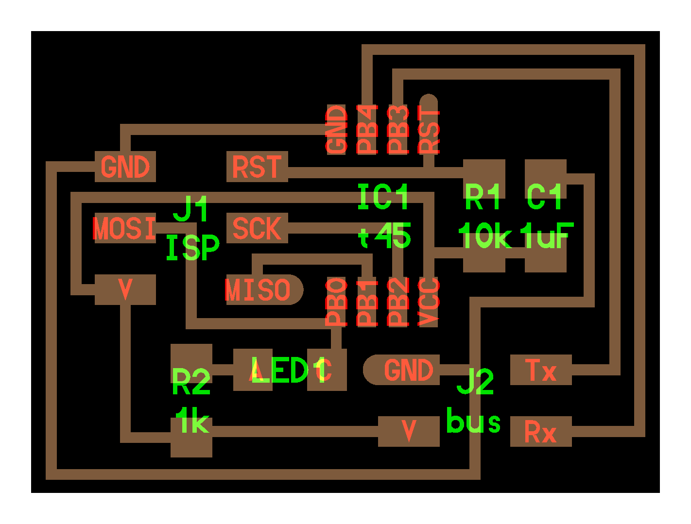
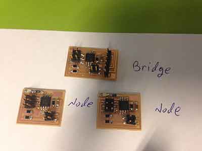
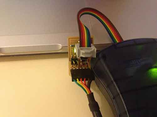
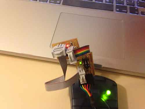
After I finished milling one bridge and two nodes I solder the components on the boards.
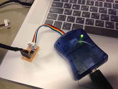
I seved the C code and makefile on my computer and conected the bridge board to the FTDI from one side and the AVR to the other.
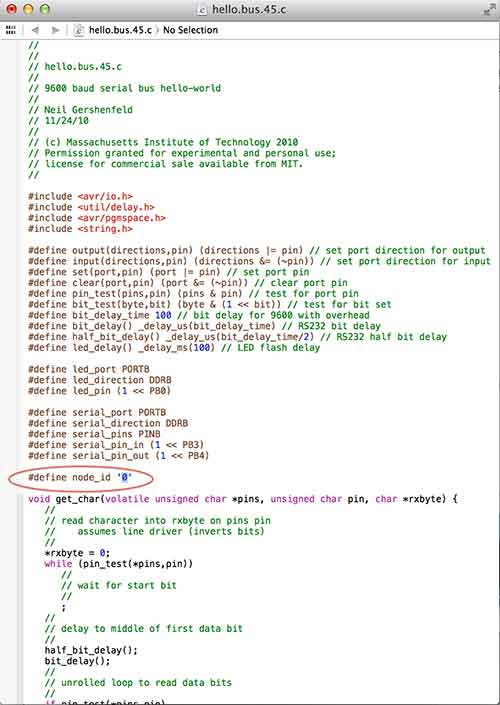
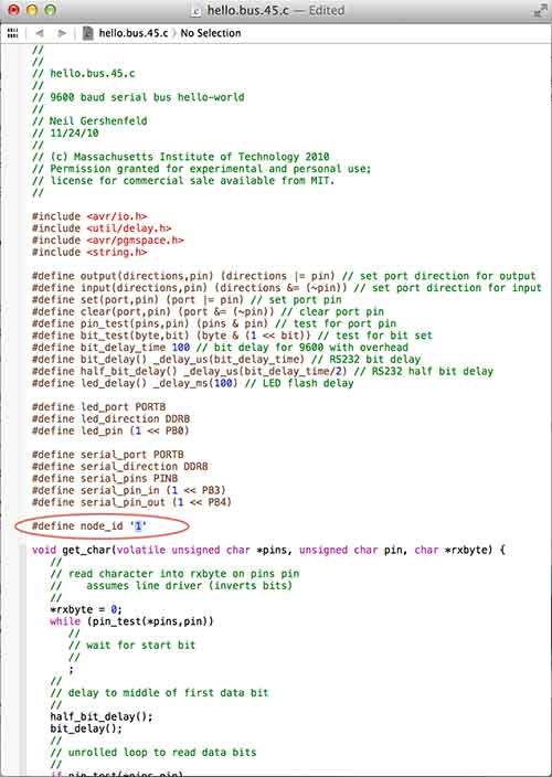
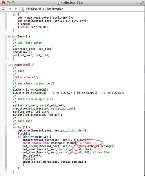
Open the hallo.bus.45 C code and examend it the bridge ID will be "0"
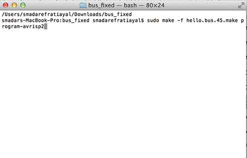
Now I opened the terminal and uploded the makefile.
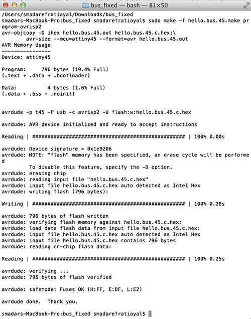
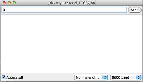
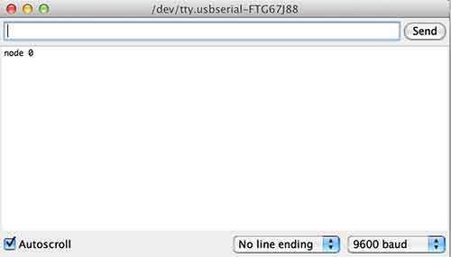
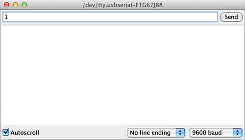
I opened the serial port in Arduino and set the rate to 9600 then I entered the ID No. to check if the programing work.
I modified the ID No. in the C code and sevd it.
I programed the board using the terminal as I did before.
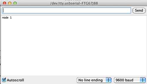
then I checked if the programig work.
I did the same steps for the third board.
After I finished I decided to modify the C code. That when I entered an ID No. 0,1,2. The serial port will rait same thing difrent then the node No.
After I finished progming the boards me and dana decided to mill two more nodes and to reaplace the led with a DC motor.
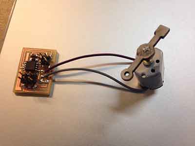
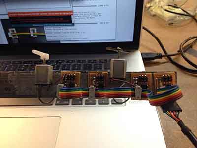
We programed the borads and conected them to echather.
I used the great Tutorial by anna kaziunas.