The main objective for the Fab Academy is that every strudent complete a final project which must involve most of the assignments we took during the course. My final project is about a controller for sound and dsp programing languages like Max/MSP or Pure Data. The controller itself helps a lot when working with both interfaces because using physical controllers makes easy to move around graphic dials and button, but if this is the case why didn't I decided to make a physical synthesizer?. The answer for this question is that both Max and PD are really powerfull software wich can make tons of audio and video processing and if you do need something else you just have to program it, in the other hand a physical synthesizer may be limited and extra modules involve design and program the hardware and that takes lots of time and effort.
Features:
The controller wokis through serial protocol from the ATmega to the computer with the software
The controller uses a touchpad for controlling either pitch, velocity or duration of notes. It also features a potentiometer that may work as a selector how it works may depend on the patch programmed in Max or PD.
The controller have 2 visual indicators, one is for power status and the other is an indicator wich can be directly connected to the potentiometer, the uses of this indicater may be modified in the firmware.
No batteries, because the controller doesn't have many sensors attached to the ATmega it's ok to power it from USB.
Project Housing:
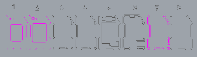
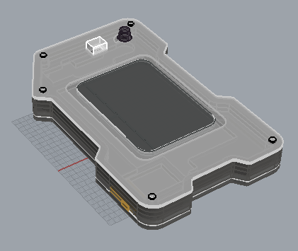
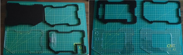
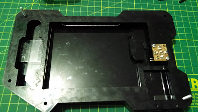
My final project housing or case it's made with laser cut acrylic. It consists on five layers of 4mm and 2 layers of 1mm with an hollow interior for storing the electronic boards. It also features three compartments for allocating the 7 segment display, potentiometer and FTDI with usb connection. The design files were made with Rhino 3D and you can download them here.
File for laser cutting
Rhino render for case
Electronics:
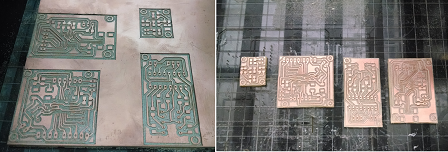
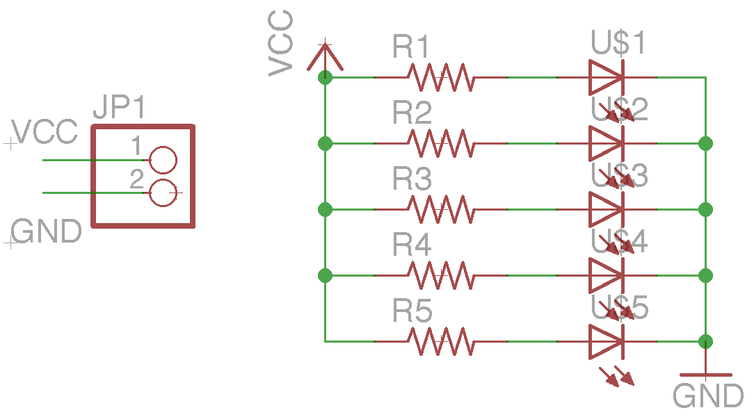
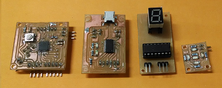
I've made 4 boards for my electronics, one of each for the microcontroller, the FTDI chip, 7 segment with shift register and leds for power status indicator.
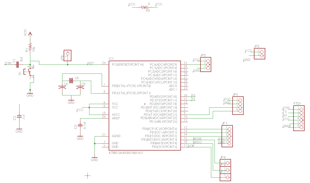
The microcontroller board is a reduced version of the fabduino with just enough pins for inputs and outputs. The board has 5 control pins for communicating with the Touchpad and the 74HC595 shift register. The other pins are just for power (VCC and gnd). I used vias instead of ISP header so it would be smaller. I made the FTDI board not only for the serial communication but for updating the firmware too.
Main controller board
FTDI board
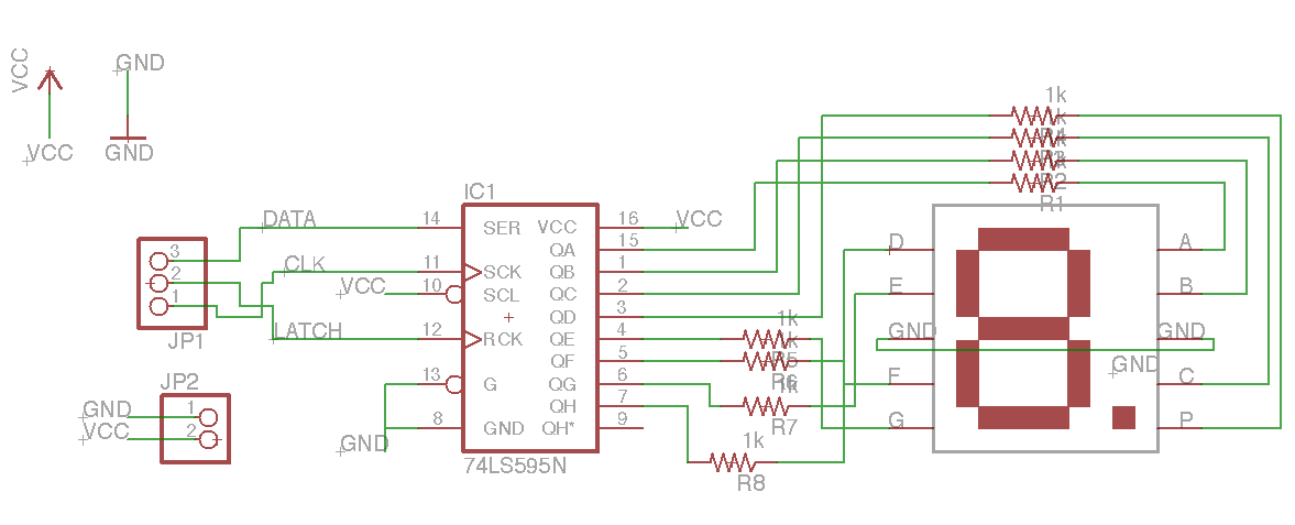
7 Segment Controller board
Touchpad functions
The board files were made with eagle, you can download them here. The boards were fabricated with the modela mdx-20, in the link from before you cand find the png files for using with the modela.
Firmware:
I decided to work with arduino because it makes programming the board faster, so I uploaded the bootloader using my Fab ISP and the FTDI board. When the bootloader has been uploaded the ISP is not necesary any more and you can just upload your sketches with the load program button in the Arduino IDE.
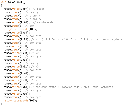
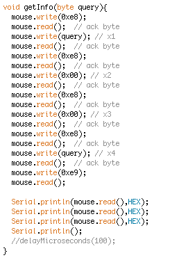
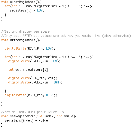
In the firmware it's important to appoint the functions for communicating with the touchpad (touch_init() & getInfo()), and the 74HC595 shift register (writeRegisters(), clearRegisters() and setRegisterPin()). Inside the setup function I configure the serial port speed and the Touchpad preconfigurations wich include the handshaking sequence and bytemode config, both prepare the touchpad for sending coordinates instead of finger displacement speed wich is the usual in the laptops.
Touchpad functions
Shift register functions
The main loop reads the coordinates all the time and scales them according the requieremens for my interface program, in this case Max/MSP. The main loop also reads the state of the potentiometer and updates the 7 segment display wich I've configured to work as a selector and indicator respectively. The serial communication with Max/MSP it's based on the Serial.println() function and appends a space (" ") between each data sent to the application. Max/MSP has a function for unpacking the data that comes through serial port.
You cand download the firmware along with the PS2 library here.
Max MSP:
Here I've implemented the functions for unpacking the data received through serial port, this data contains the x and y coordinates, the potentiometer state and a value that indicates when there's been interaction with touchpad. Next the values from the coordinates and touchpad interaction are sent to a functions that converts them into midi notes from one octave (13 different notes). The new note values are ready to be sent to the speaker but instead I decided to process them with an ADSR envelope. For the envelope the potentiometer sets three preconfigurated ADSR values and a manual selection tool, with this the sounds will have some sound effects.