|
|
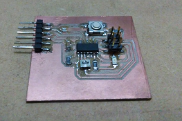
This week assignment is to redraw the "echo hello board" adding a button and a LED with a current limiting resistor, and finally make it with the Modela mdx-20 and solodering the components.
So for the first part of the assignent we have to download Eagle and install it. Eagle can run as a freeware but it's limited to a layout routing area of 100x80 mm, but it's ok since our board has few components and is small.

Getting started with eagle
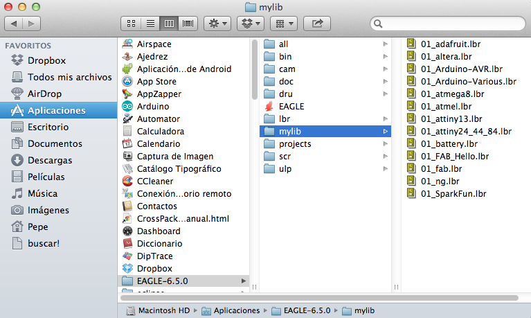
The first thing we need for our assignment are the libraries with the componentes we are using in the Fab Academy, so go ahead and download it from here. Unzip it and place it in any directory you want.
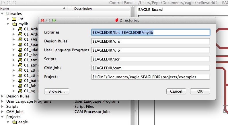
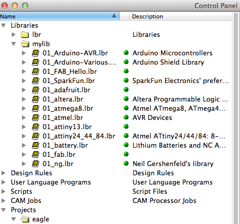
Open eagle, choose Options>Directories. If you're using MAC you have to add ":" and the path of the component libraries. Windows users may write first ";" and then the path of the libraries. Back in Eagle control panel search within libraries the folder "eagle libraries" right click and "Use all".
SCHEMATIC VIEW
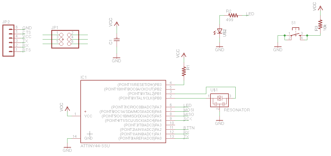
Now we're ready to start drawing our board. Eagle has two main views, Schematic and Board layout. The first step is to make the schematic file, so create a new project and a new schematic file. A schematic is a representation of a circuit, it contains the components as simplified standard symbols. Our final schematic should look like this:
In eagle we can work using the GUI Buttons or typing in the command line.

If you want to work with command line just type the name of the function and select the component you want to interact with. Heres a list of some commands:
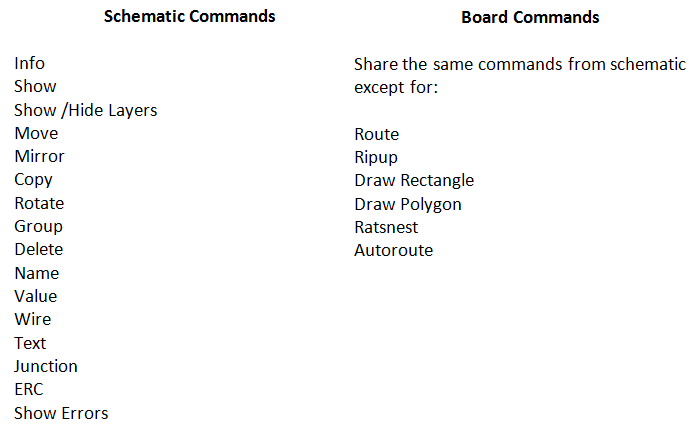
Most of the components used for the design of the board are in the 01_FAB_Hello library, the resonator is in 01_fab and finally the 6 pin male header is in 01_SparkFun. Add all the components and then wire them and rename the nets. Finally check for any errors with the ERC command. For elecronic design you must consider the polarity of some compoennts like the LED or some polarized capacitors (not used in this assignment). In the case of the LED the cathode must go to ground.
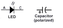
Some Polarized Componentes
The assignment mentions using a limiting current resistor, the value of the resistor must be calculated considering the LED datasheet values for forward current and forward voltage. In the next graphic I show how to calculate it:
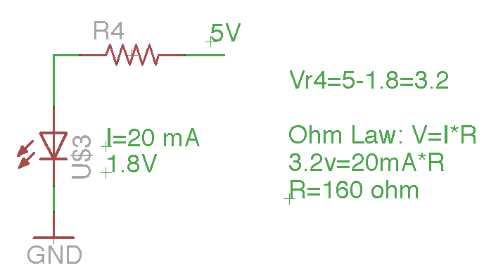
I couldn't find a resistor with a value of 160 ohm in the lab, for this reason it's ok to use another close value. In the inventory I found 499 Ohm.
BOARD LAYOUT VIEW
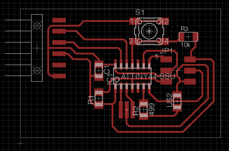
Here you must arrange the components and then route manually or use the autoroute option. There are some considerations while arranging the components, the resonator or crystal must be close to the microcontroller, as indicated by Atmel here on page 14. Second the capacitor works as a decoupling capacitor and it must be close to MCU as well, as they ensure the voltage keeps constant all the time. When i first designed the board i connected the led on pin 11 and the button on pin 10 and it was harder to route so i moved the led to pin 6, there was more space in that part of the board. Now my board look like this:
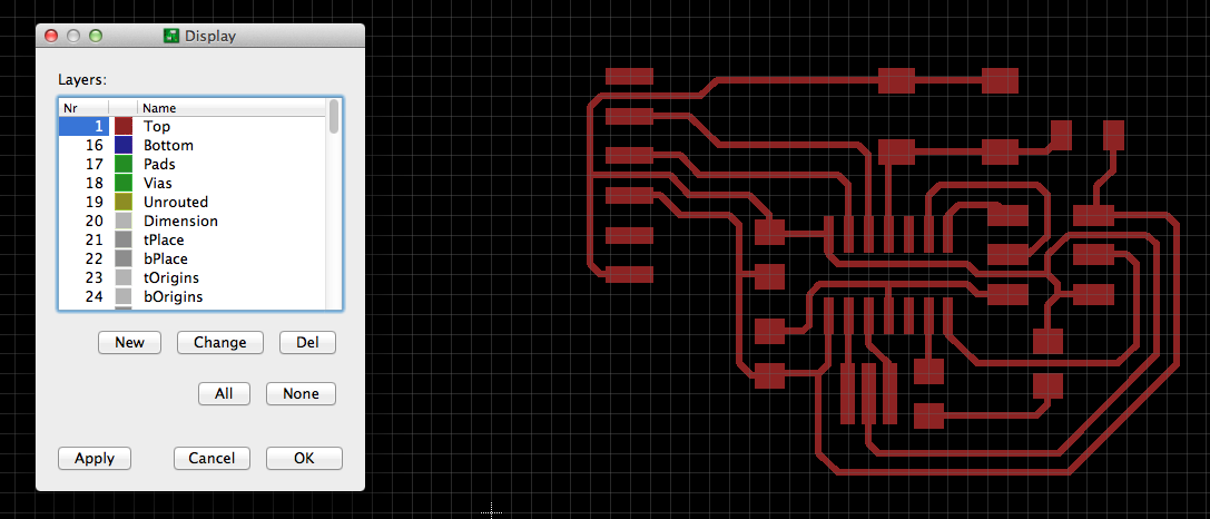
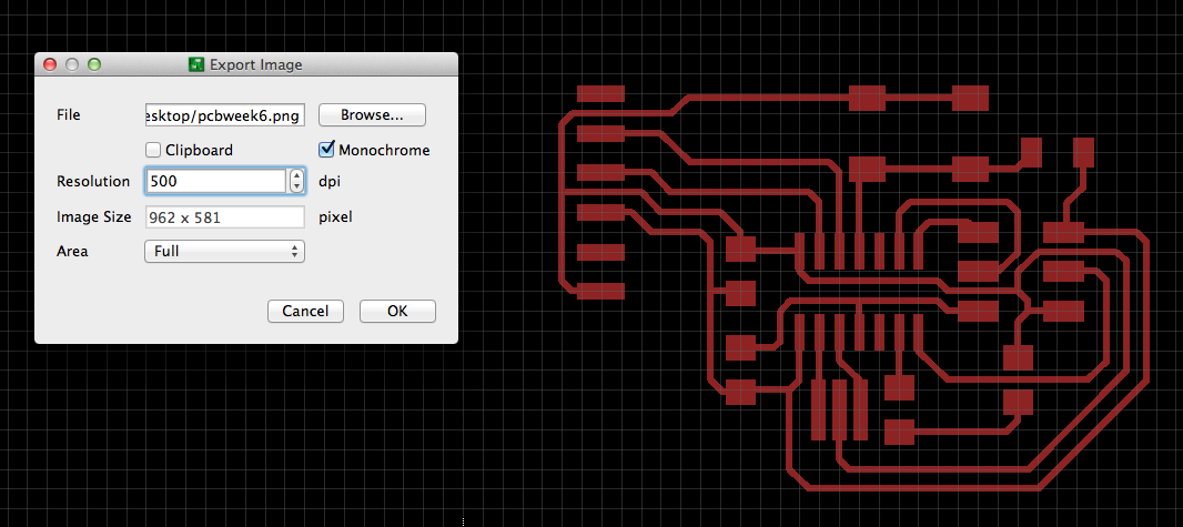
The next step is to realocate the dimension layer and export remove all layers except Top and export it. To export simple go to File>export>image, then choose 500 dpi and monochrome and the path you're going to save the image file.
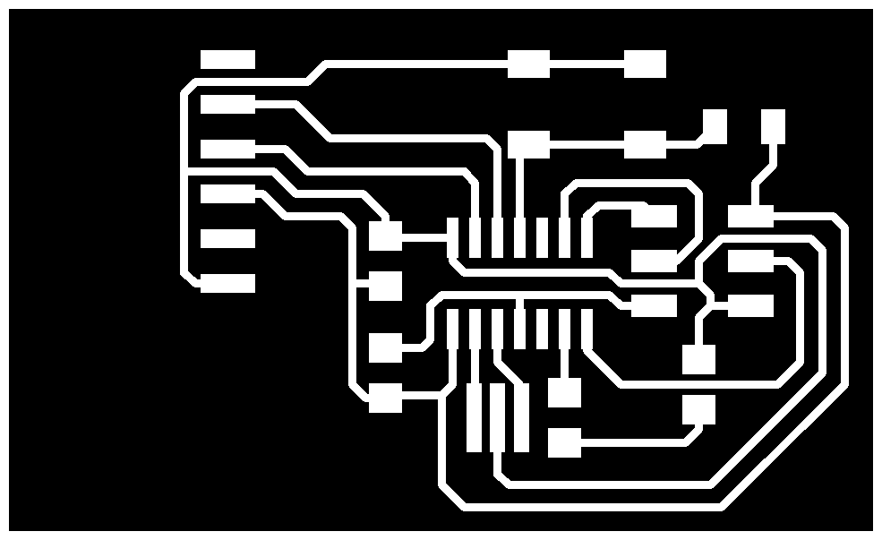
The final step is to add an external white frame in gimp or photoshop and the board is ready to send to the mdx-20.
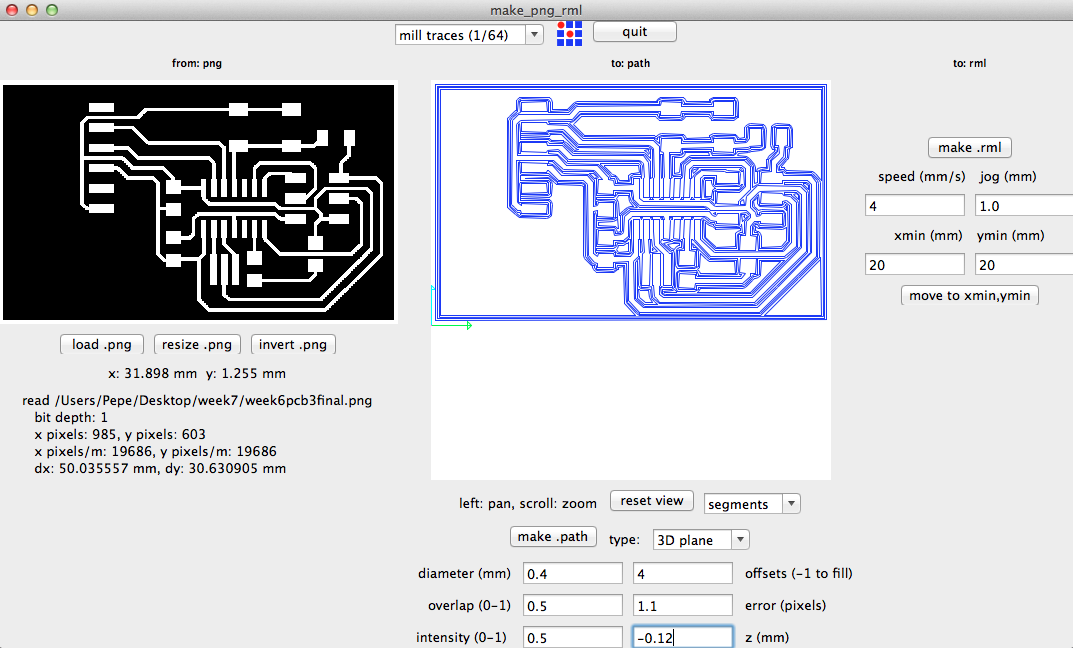
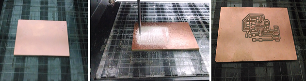
FABRICATION AND SOLDERING
The process for fabricating the pcb was the same from fab isp in electronics production assignment.
|