The goal for this week is to make the FAB ISP programmer. The first step is to install the FAB Modules wich can be downloaded from here, along with the system requirements and steps for installation.
Using the Modela MDX-20
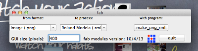
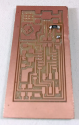
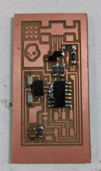
With the FAB Modules installed download the hello.ISP.44.traces.png file and personalized it in GIMP with the same logo I cut in the GX-24. Next in the FAB Modules configure the input format as PNG, the Roland Modela make_png_rml process and program.
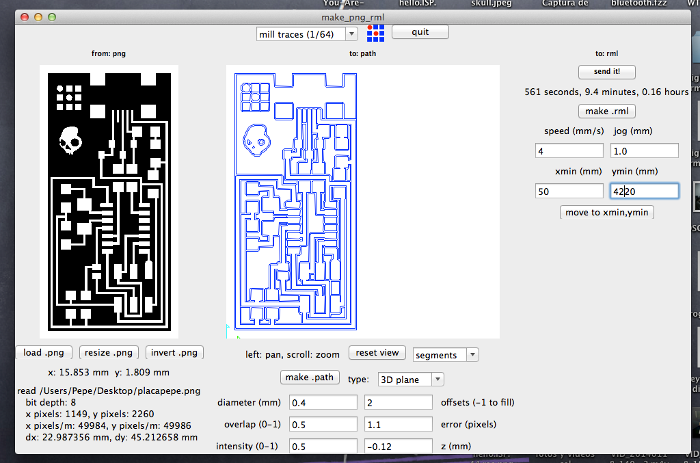
In this new window set the parameters of the mill. Then attach the board with double side tape in the center of platform of the mdx-20. Finally set the origin coordinates and execute the commands make.path, make.rml and send it!
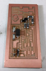
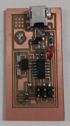
The next step is to solder the components, it is recommendable to use a soldering iron with a thin tip, tweezers and solder wick to avoid shorts between pins. A personal recommendation for surface mount soldering it's to put some lead into one of the pads and then place the components in place with the tweezers, then heat the pad with the soldering iron.
Materials
In the case of components with several pins like the microcontroller or the usb connector, with narrow traces, soldering is more complex and solder wick helps a lot to avoid shorts after soldering.
Programming the FAB ISP
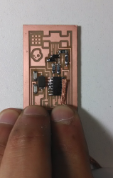
When all components have been soldered, then connect pins SJ2 and SJ1, it is important to do this for programming the FAB ISP.
First plug the AVR MKII and make sure the led goes from red to green.
If your operative system is MAC OS X it's important to install avrdude, gcc compiler and AVR Crosspack, then download the firmware ATtiny44 ISP. From the terminal go to the folder that contains the firmware and run the following commands.
make clean
make hex
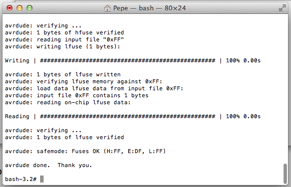
sudo make fuse
sudo make program
In linux you can check if your ATTiny44 was succesfully programmed with the command lsusb, but in MAC you must have to do:
about this mac> more info > system information > USB
it should look like this:
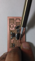
Finally desolder JS1 and JS2 and the ATTiny ISP programmer is ready!
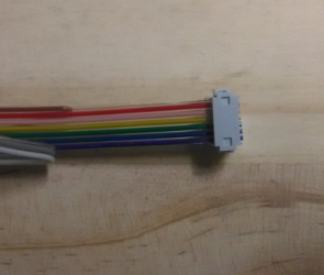
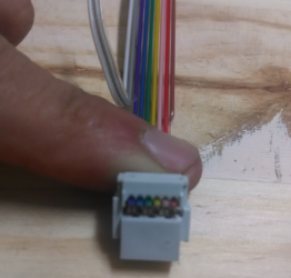
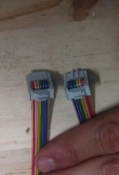
Assembling the IDC ISP Cable
For this you need the IDC connectors and flat cable.