This week assignment is about output devices. An output device is a device used to send data from a computer, or in this case, a microcontroller that enables an output pin to activate a device, such as an LED, LCD, motor drivers, etc. For this week I chose LCD and RGB Led boards.
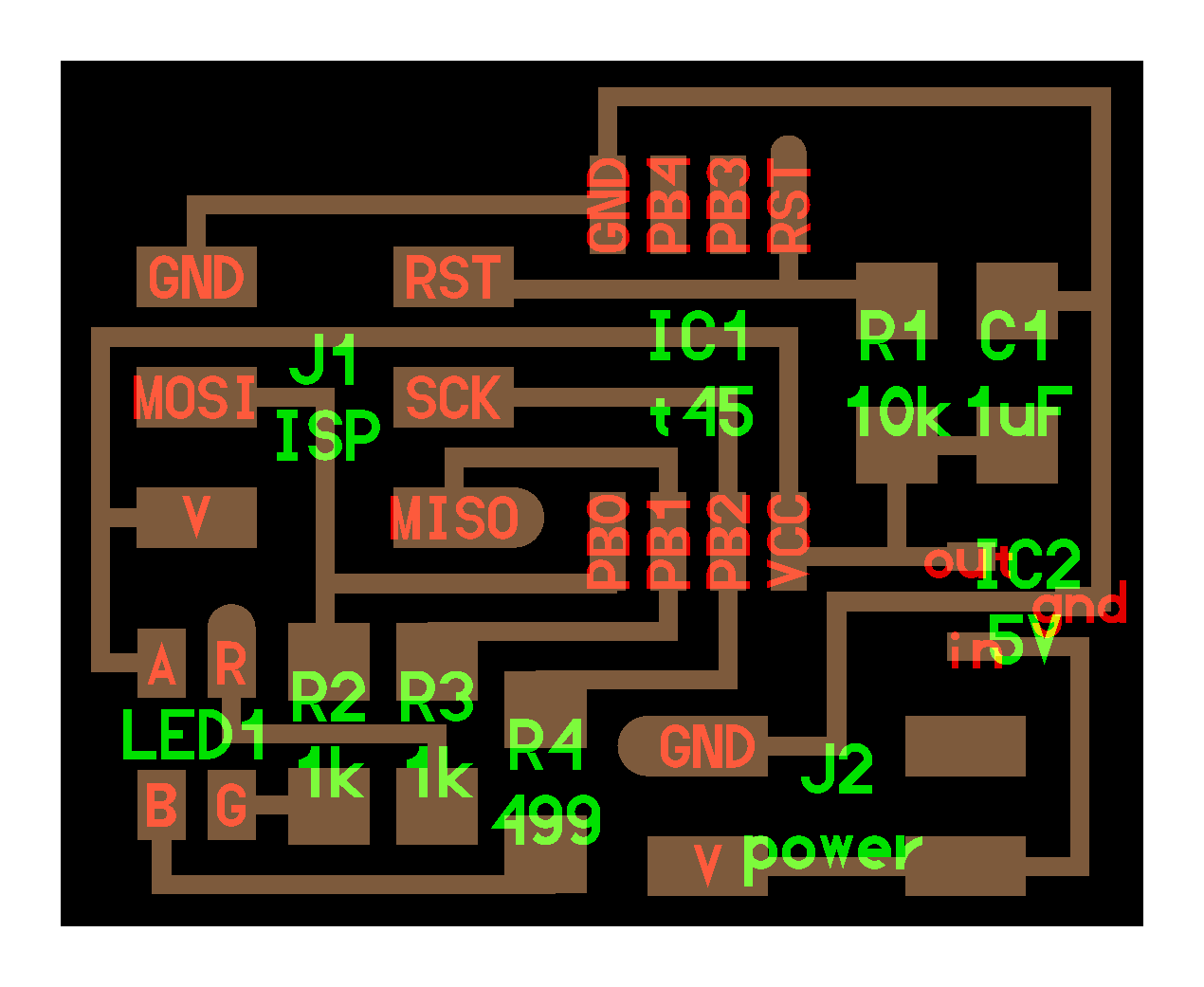
RGB Board:
Because we're not using an FTDI board to source power we have to connect a battery on the board. We can use a 9V bat with no problems because of the regulator included in the board. So plug the batter, and check for correct voltage, and in Terminal use the command:
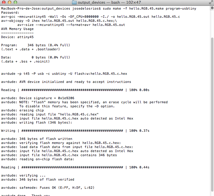
sudo make -f hello.RGB.45.make program-usbtiny.
If everythings is okay the LED will fade through all colors.
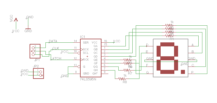
7 Segment Display:
I made this board to include a 74HC595 Shift register and connected to the Main controller for my final project. You can find the eagle files here.
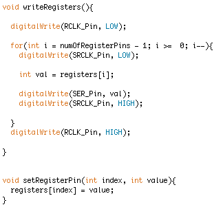
The first thing I did was to get the mapping for my seven segment display and code the pins on the the shift register. The 74HC595 receives data through serial and converts this data into a state for each of it's output pins, this is like a serial to parallel converter. The register set happends in to a LOW to HIGH state and it's synchronized by a clock(SRCLK).
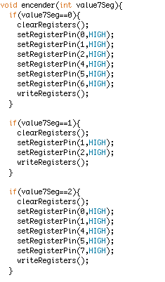
In the source code I've implemented one function to code some values from 0 to 9 this assign each pin from the 74HC595 to it's corresponding LED on the display.
The other functions implements clear and write registers.