|
|
This week assignment is to make Something Big, and for this we're going to use the Shopbot. The shopbot is do-all tool for substractive process, like carving, drilling, cutting. This machine fits in the CNC group but now they are called digital fabrication tools, because CNC is often used to refer the machines we find at industrial factories. Some info about the Shopbot machine we're going to use:
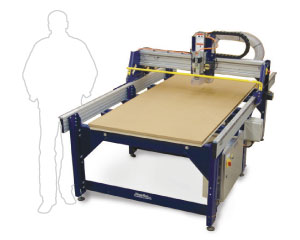
Model: PRSalpha48
Dimensions: 2.44m x 1.52m x 0.15m
Software: PartWorks 3 (included with machine)
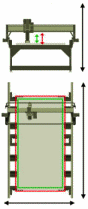
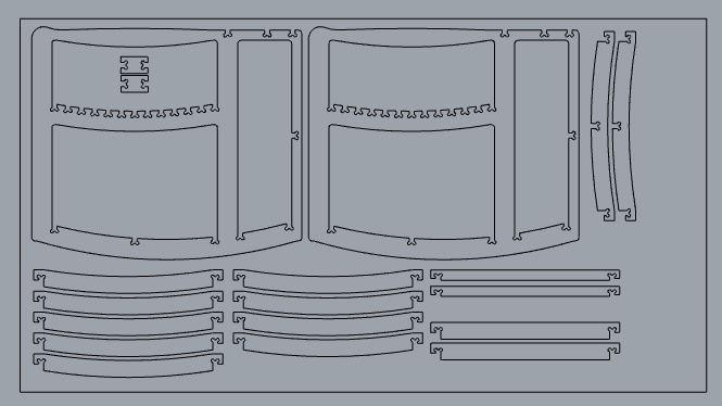
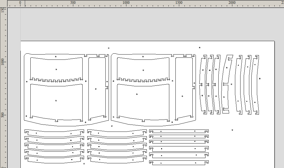
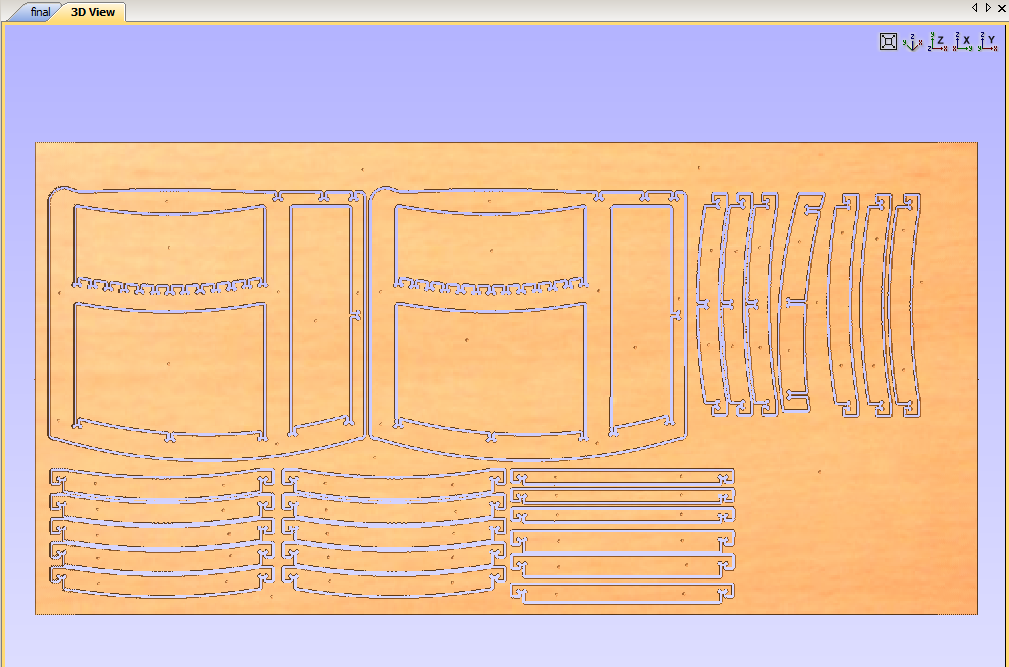
I decided to make a rocking chair, for this I took measures of any chair I could find at hand. The important measurements are the distance from the seat to the ground, the distance from the arm rest to the seat, width, height and depth of the chair and finally the rockers curvature as a 32.8º arc based on the height from the ground (approx. 6cm). I made the model in Rhino wich you can download here and fit all the pieces in a rectangle with dimensions 2440 mm x 1200mm wich is inside the machine workspace dimensions. The chair is designed to work as a big press-fit construction kit, the material I picked was 15.4mm thicknes plywood. Before modelling don't forget to measure you material thickness with a caliper, is important if you are doing press-fit kits.
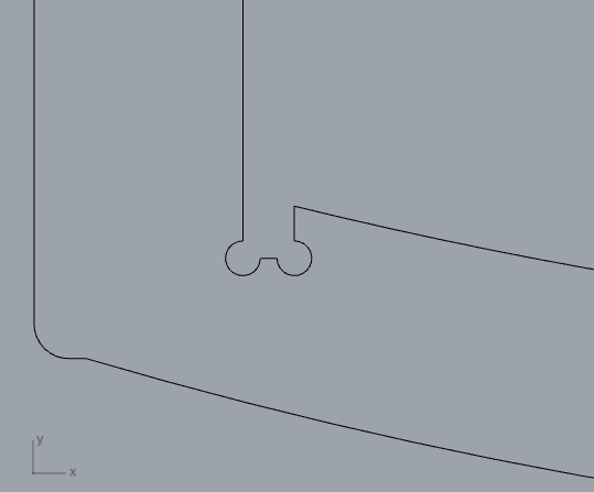
The shopbot can cut 90º angles in the inner sides, so a recommendation is to make some "ears" in the corners, just like the image:
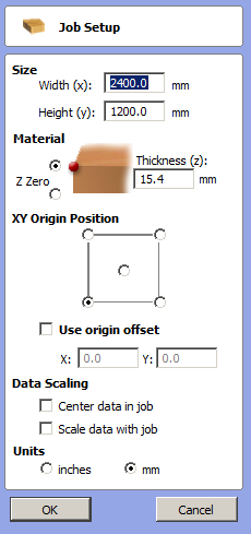
The next step is to export the Rhino model to PartWorks 3 interface. Export the model as a DXF format file and open the file in PartWorks 3 (not 3D). Within PartWorks is important to adjust the size of the work area as 2.44m x 1.3m, then set the material thickness and finally realocate the whole model in the origin position.
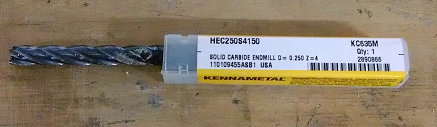
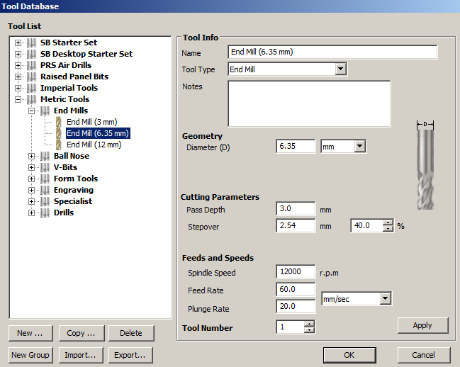
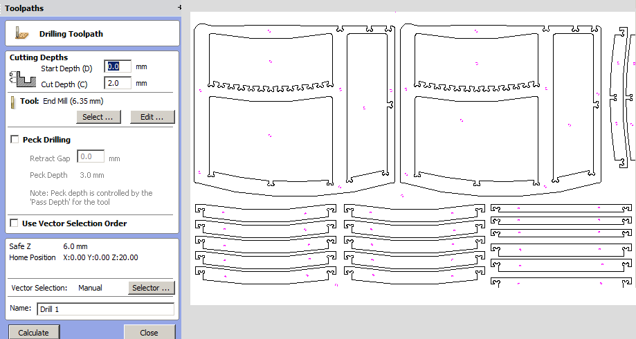
The first step for machining, is to place circles for the screws that will fix the position of the material along the sacrificial layer. I used 6mm diameter screws, so the circles will have the same diameter. Then you have to create the toolpaths, in this case a drill toolpath works great. By this time you must know your end mill measurements, I used a carbide 0.250 inch diameter (6.35mm) and Z height of 4 inch (around 102 mm). The idea of this toolpath is to make a mark around 2mm depth for the screws we are going to use for securing the material board to the sacrificial layer. Make sure to choose the right end mill according to the one you have at the lab. Then hit simulate and the toolpath is ready.
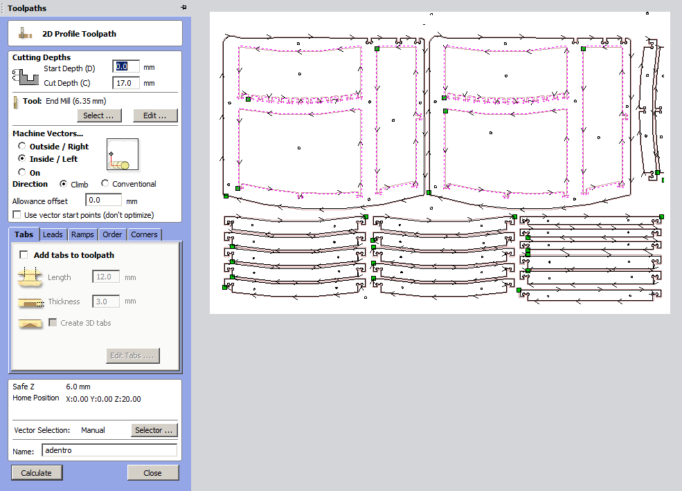
The next Step is to make the cutting or profile toolpaths, here you have to select the cut depth around 1mm or 2mm beyond your material thicknes, I set it at 17mm. Depending on your model the machine vectors must be chosen as outside, inside or on the line, which best fits your design. After this hit simulate again and the toolpath will be ready. When all the toolpaths are ready, export them and they're ready for cutting.
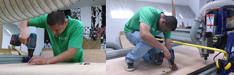
Machining
Some security recommendations:
Wear Glasses
Use ear protection
Keep distance when the machine starts the cut
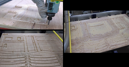
Open the Shopbot console and calibrate the X/Y axis and finally calibrate the Z axis. The Z axis must be calibrated before cutting the drill toolpath and after. Finally send the profile and wait until the cutting is done.
Final comments
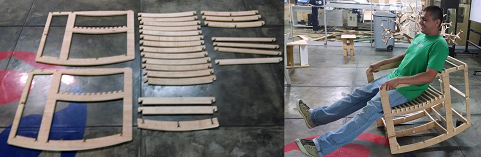
Even after making some press-fit test with the material and adjusting many times the tolerance, the machined pieces didn't fit with their counterparts, this is because the plank was not regular and some pieces end up broken. Some modifications I'd like to do is the use of screws and avoid the press-fit for small pieces or simply use a more regular plank of plywood.
|