20. Final project requirements
Final Project Slid
here is the slide of the final project

Final Project video
Here is the video of the final project
Final Project Page
Here is the Final Project Page which has the project summery
CafeBot
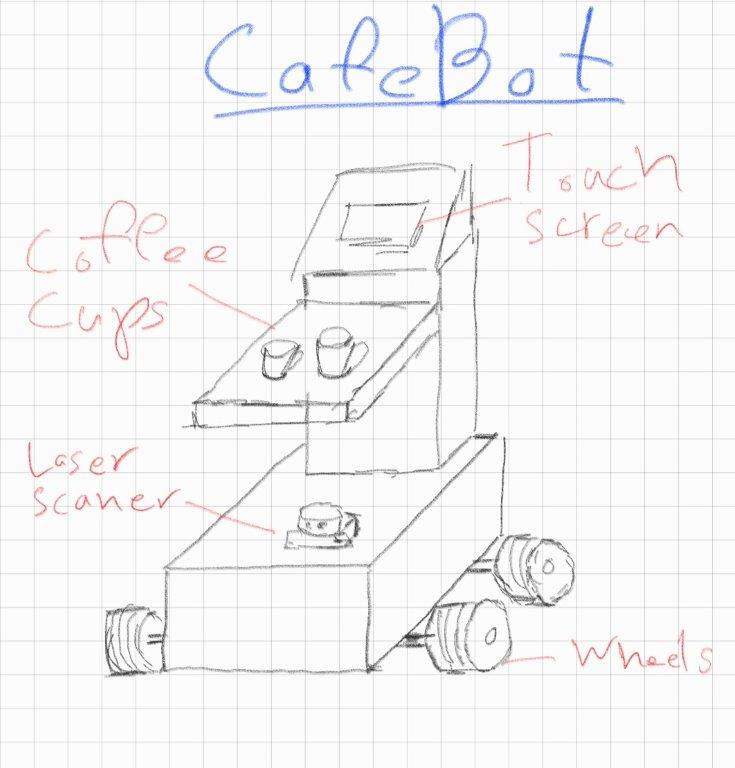
What does it do?
CafeBot is a Robot for Coffee Delivery in a coffee shop. This robot will help the barista to focus in making good coffee and the robot will deliver the coffee to the customer. Also this robot will help to keep the social distance during COVID-19 pandemic.
Who’s done what beforehand?
During COVID-19 there are a lot of demand robot delivery.
-
PuduBot is indoor Delivery Robot for Restaurants
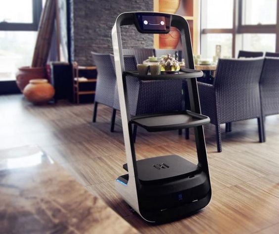 pudurobotics.com
 -
Bear Robotics, a company making robot waiters
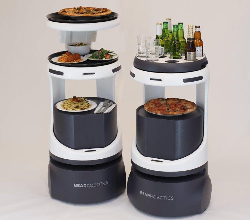 bearrobotics.ai
What did you design?
In this project I’ll Design the Following:
- Electronics circuit and PCB design
- 3D Design of the Robot frame
- Software and Application Design
- Logo
Electronics
In Electronics Design week I have designed a custom microcontroller board for this project
In Embedded programming week I programed the microcontroller and test it
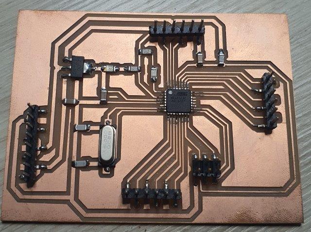
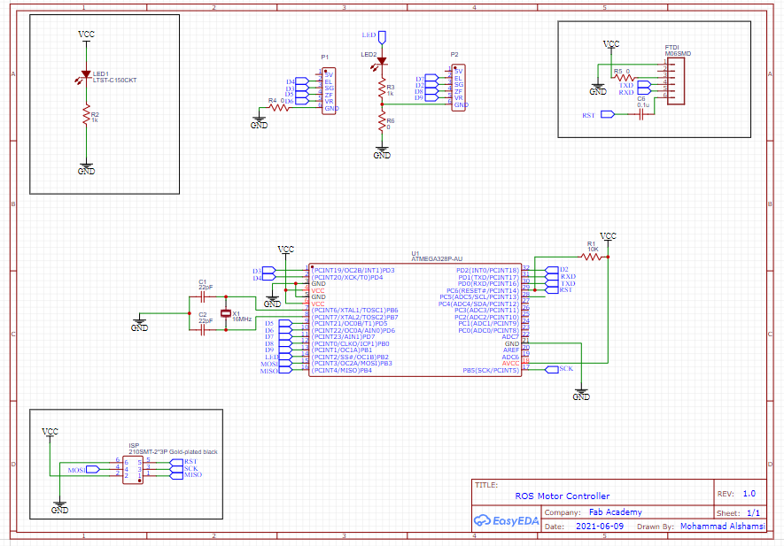
New Motor Controller
To avoid using Jumper wires I decided to to design new a new motor controller.
For to designing the the motor controller I update my microcontroller design which I designed in Electronics Design week using EasyEDA
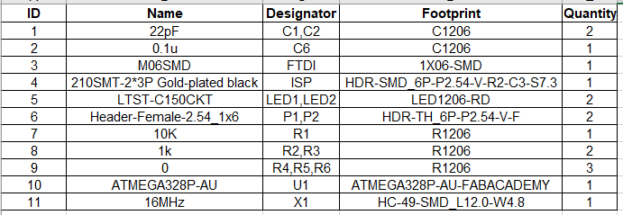
I Started the design with the schematic and BOM
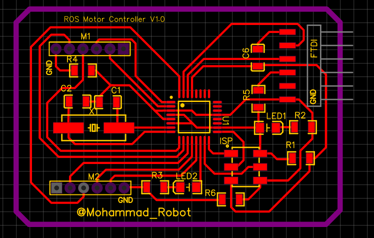
Export the schematic to PCB and make the route manually
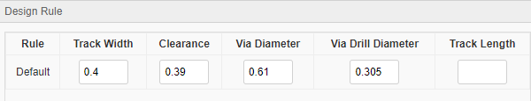
Set the Design Rule and run DRC tools to check for any error
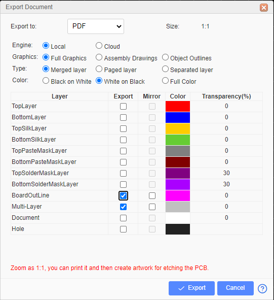
For the best quality Export the design to 2 PDF files one for traces and one for outline and holes
- Traces Export:
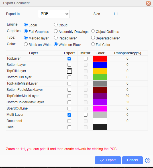
- Outline Export
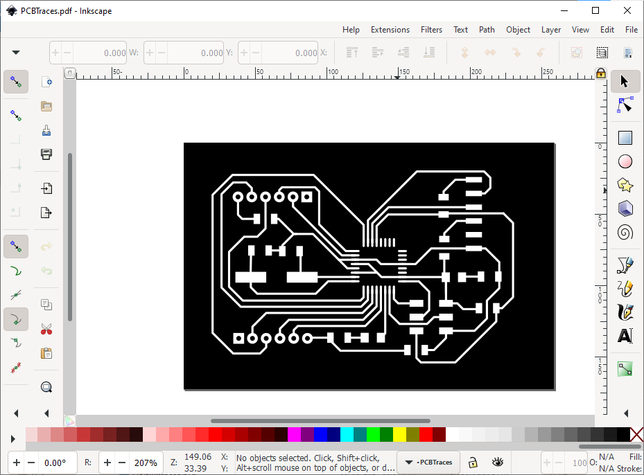
open the PDF file with Inkscape software and save it as SVG file
For the Outline edit the file with Inkscape and fill the inside the white color. To do that change the Threshold to 100. then save the file as SVG
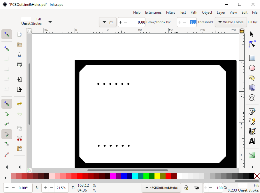
Here are the Two SVG files


Upload the files to fab modules and create the G-code. For more details about Electronics production check my Electronics production Week
Here is the new Motor Controller

3D Design
To speedup the design process I have started downloading 3d modules for the components of the project
- Download 3D 7in touch Screen design from grabcad.com
- Download 3D Models for RPLIDAR sensor from slamtec.com
- Download 3D coffee cup from grabcad.com
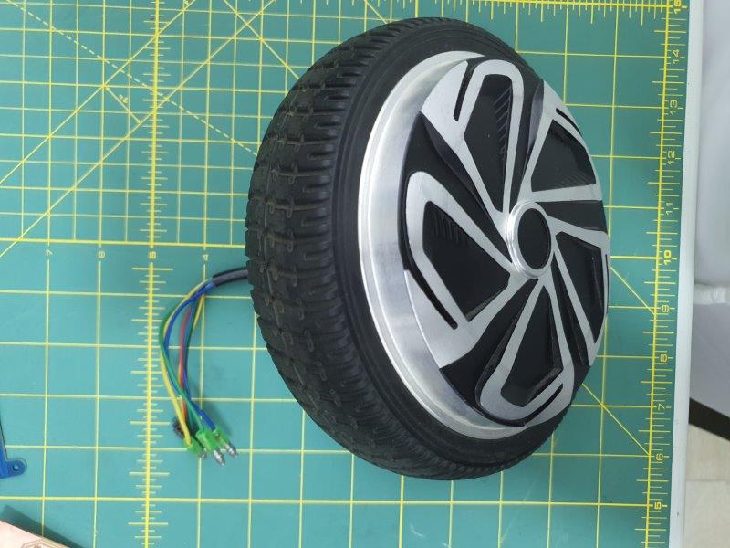
- Download Motor Wheel from grabcad.com
Here is a initial 3d skitch for the CoffeeBot
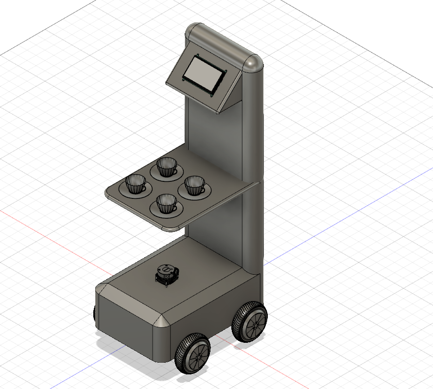
But the issue with this design is very hard to make and it doesn’t look good overall, so I have decided to make a new design which looks way better.

Here is the 3 View of the Design

Start design with the base of the robot

For the motor here is the dimensions for the Motor Wheel
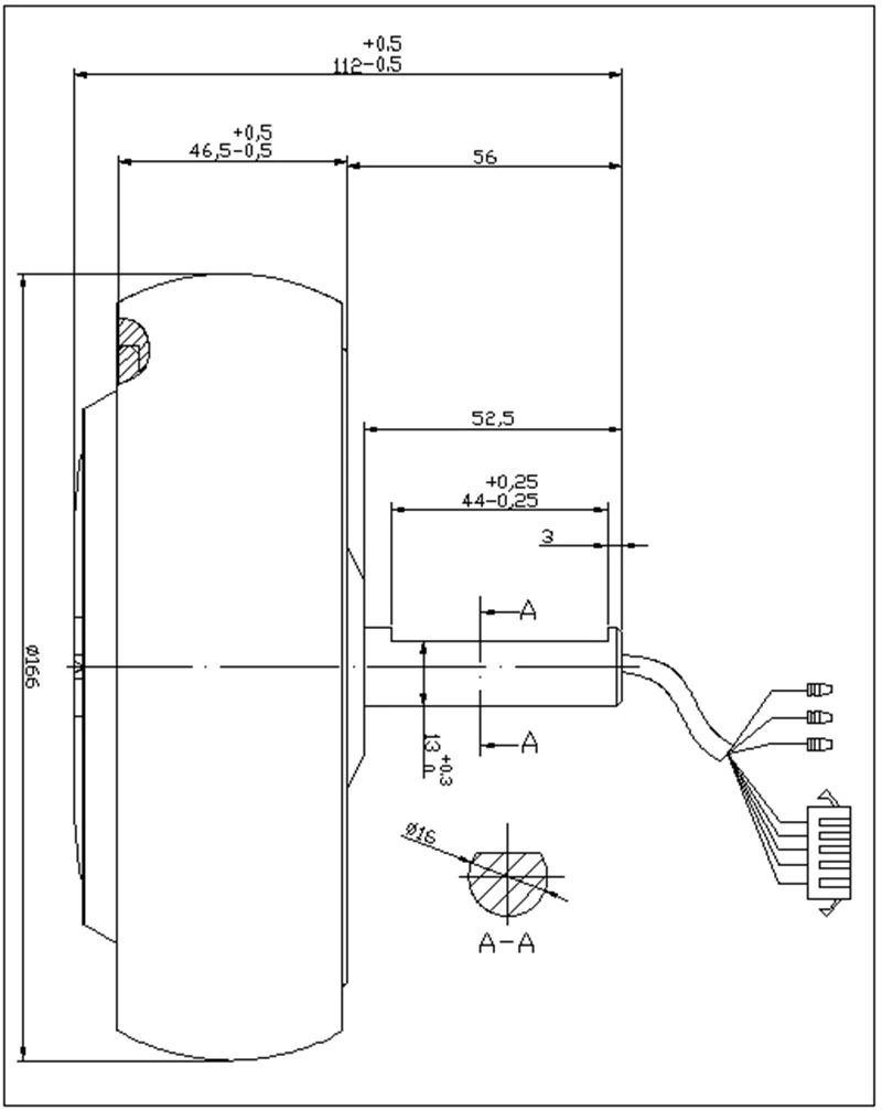 https://www.streetsaw.com
I have designed the motor bracket to hold the motor wheel
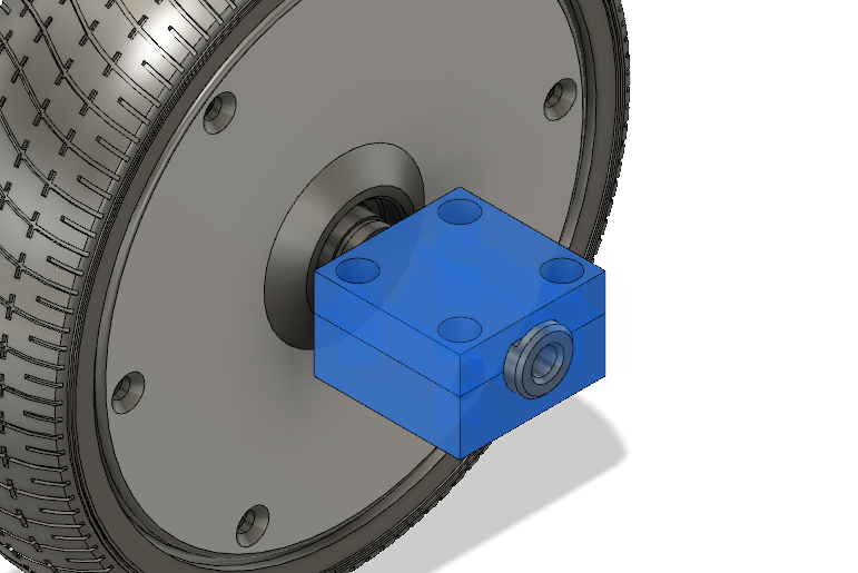
Assemble the motor wheels with base

Add Aluminum Profile to support the structure

Design the side frame

Compete the design by making shelf and cover the wheels
Fabrication
Started with laser Cutting machine to cut the base 6mm acrylic sheet

I found that the Acrylic sheet is strong to hold the motor so I have decided use shopBot machine to cut the white HDPE plastic which is stronger than acrylic

3D print the motor clamp to hold the motor with base of the robot

Laser Cut the frame of the robot and body of the robot


Assembly
I have started assembly with motors and base of the robot

Assemble the frame of the robot

Assemble the fame and base together

Remove Acrylic protection layer and here is the robot

Motor
In Output devices week I have tested the Motor Wheel and make sure I can control the speed and direction.
Power Consumption
I have installed Two motors in my Robot and check the current consumption.
- First test in desk without load.
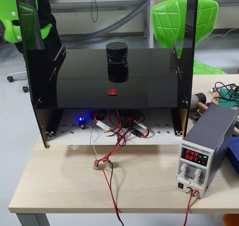
Power = Current x Voltage = 0.07A x 24.4V =1.708W
Power for each motor = 1.708 / 2 = 0.854W
- Second test with load and robot moving in the floor.
Power = Current x Voltage = 0.27A x 24.4V =6.588W

Power for each motor = 6.588 / 2 = 3.294W
Software
for this project I’ll use ROS
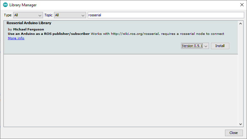
ROSSerial
- Install ROS Serial Library in Arduino IDE
ROS Navigation
In order to complete this project I need to learn more about ROS Navigation. Here are some useful tutorial.
ROS NAVIGATION IN 5 DAYS
- ROS NAVIGATION IN 5 DAYS #1 - Course Overview & Basics Concepts
- ROS NAVIGATION IN 5 DAYS #2 - Mapping & Create a map from zero
- ROS NAVIGATION IN 5 DAYS #3 - Robot Localization
- ROS NAVIGATION IN 5 DAYS #4 - Path Planning - Part 1
- ROS NAVIGATION IN 5 DAYS #4 - Path Planning - Part 2
Building a ROS Robot
- Building a ROS Robot for Mapping and Navigation #1
- Building a ROS Robot for Mapping and Navigation #2
ROS requirements In order to do Navigate by ROS you need to provide the Following data:
- Laser Data
- Odem Data
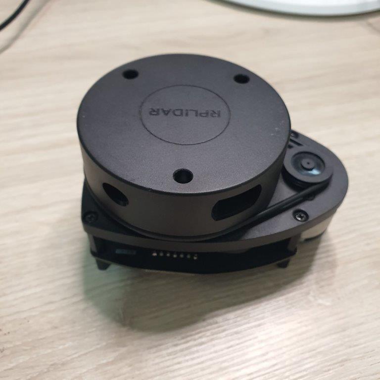
In Input devices week I have tested the RPLIDAR sensor which is the 2D 360 laser scanner for mapping and navigation.
ROS Transforms
we need to provide Laser sensor location in the robot in order to generate map
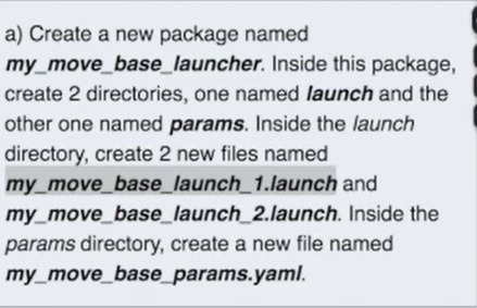
ROS Launch ROS Launch file has all the parameters and nodes which are require to preform this task.
To create Launcher file run the following commands

I’m not able to integrate with ROS because the microcontroller ATMEGA328 can’t handle ROSSerial, So I need to change it to more powerful microcontroller.
Due to time restriction I decided to use motor encoder and program the robot to move in predefined path.
The Robot will move in following sequence - Move forward for 2 meters - Stop - Turn left 90 degree - Move forward for 2 meters - Stop
Here is the Code
#include <PID_v1.h>

///////////Motor Drivers//////////////////
const int rightMotorELPin = 4;
const int rightMotorSignalPin = 3;
const int rightMotorDirPin = 5;
const int rightMotorPWMPin = 6;

const int leftMotorELPin = 7;
const int leftMotorSignalPin = 2;
const int leftMotorDirPin = 8;
const int leftMotorPWMPin = 9;

double rightMotorPWM = 0;
double rightMotorSpeed = 0;
double rightMotorEncoder = 0;
double setRightMotorSpeed = 0;
unsigned long rightMotorEncoderTime = 0;
unsigned long rightMotorEncoderPvTime = 0;
int rightMotorDistance = 0;

double leftMotorPWM = 0;
double leftMotorSpeed = 0;
double leftMotorEncoder = 0;
double setLeftMotorSpeed = 0;
unsigned long leftMotorEncoderTime = 0;
unsigned long leftMotorEncoderPvTime = 0;
int leftMotorDistance = 0;

//Specify the links and initial tuning parameters
double Kp = 200, Ki = 100.0, Kd = 0.001;
PID rightMotorPID(&rightMotorSpeed, &rightMotorPWM, &setRightMotorSpeed, Kp, Ki, Kd, DIRECT);
PID leftMotorPID(&leftMotorSpeed, &leftMotorPWM, &setLeftMotorSpeed, Kp, Ki, Kd, DIRECT);


String inputString = "";         // a String to hold incoming data
bool stringComplete = false;  // whether the string is complete

int i = 0;
char Char = "";

void setup()
{
  pinMode(rightMotorELPin , OUTPUT);
  pinMode(rightMotorDirPin , OUTPUT);
  pinMode(rightMotorPWMPin , OUTPUT);

  pinMode(leftMotorELPin , OUTPUT);
  pinMode(leftMotorDirPin , OUTPUT);
  pinMode(leftMotorPWMPin , OUTPUT);

  pinMode(rightMotorSignalPin, INPUT_PULLUP);
  pinMode(leftMotorSignalPin, INPUT_PULLUP);

  attachInterrupt(digitalPinToInterrupt(rightMotorSignalPin), readRightMotorEncoder, CHANGE);
  attachInterrupt(digitalPinToInterrupt(leftMotorSignalPin), readLeftMotorEncoder, CHANGE);

  digitalWrite(leftMotorELPin, LOW);
  digitalWrite(rightMotorELPin, LOW);

  //turn the PID on
  rightMotorPID.SetOutputLimits(0, 100);
  rightMotorPID.SetMode(AUTOMATIC);

  leftMotorPID.SetOutputLimits(0, 100);
  leftMotorPID.SetMode(AUTOMATIC);

  // initialize serial:
  Serial.begin(9600);
  // reserve 200 bytes for the inputString:
  inputString.reserve(200);
}

void loop()
{
  // Move Forward
  if (i == 0) {
    digitalWrite(rightMotorDirPin, LOW);
    digitalWrite(leftMotorDirPin, HIGH);
    digitalWrite(leftMotorELPin, HIGH);
    digitalWrite(rightMotorELPin, HIGH);
    setRightMotorSpeed = 0.2;
    setLeftMotorSpeed = 0.2;
    Serial.println("Forward");
    i = 1;
  }
  //Stop afer 2 meters
  if (i == 1 && rightMotorDistance >= 2000) {
    rightMotorDistance = 0;
    setRightMotorSpeed = 0;
    setLeftMotorSpeed = 0;
    i = 2;
  }
  // Turn Left
  if ( i == 2 ) {
    digitalWrite(rightMotorDirPin, LOW);
    digitalWrite(leftMotorDirPin, LOW);
    digitalWrite(leftMotorELPin, HIGH);
    digitalWrite(rightMotorELPin, HIGH);
    setRightMotorSpeed = 0.1;
    setLeftMotorSpeed = 0.0;
    Serial.println("Left");
    i = 3;
  }
  // Stop
  if (i == 3 && rightMotorDistance >= 300) {
    rightMotorDistance = 0;
    setRightMotorSpeed = 0;
    setLeftMotorSpeed = 0;
    i = 4;
  }
  // Move Forward
  if (i == 4) {
    digitalWrite(rightMotorDirPin, LOW);
    digitalWrite(leftMotorDirPin, HIGH);
    digitalWrite(leftMotorELPin, HIGH);
    digitalWrite(rightMotorELPin, HIGH);
    setRightMotorSpeed = 0.2;
    setLeftMotorSpeed = 0.2;
    Serial.println("Forward");
    i = 5;
  }
  // Wait for 2 meters
  if (i == 5 && rightMotorDistance >= 2000) {
    rightMotorDistance = 0;
    i = 6;
  }
  // Stop
  if (i == 6) {
    digitalWrite(leftMotorELPin, LOW);
    digitalWrite(rightMotorELPin, LOW);
    setRightMotorSpeed = 0;
    setLeftMotorSpeed = 0;
    Serial.println("Stop");
    i = 7;
  }


  Serial. print(i);
  Serial.print ("  ");
  Serial.println(rightMotorDistance);

  if (rightMotorEncoder != 0) {
    rightMotorSpeed = ((rightMotorEncoder * 6) / (rightMotorEncoderTime - rightMotorEncoderPvTime)); // speed in m/s
    rightMotorDistance += rightMotorEncoder * 6;
    rightMotorEncoder = 0;
    rightMotorEncoderPvTime = rightMotorEncoderTime;
  } else {
    rightMotorSpeed = 0;
  }

  if (leftMotorEncoder != 0) {
    leftMotorSpeed = ((leftMotorEncoder * 6) / (leftMotorEncoderTime - leftMotorEncoderPvTime)); // speed in m/s
    leftMotorDistance += leftMotorEncoder * 6;
    leftMotorEncoder = 0;
    leftMotorEncoderPvTime = leftMotorEncoderTime;
  } else {
    leftMotorSpeed = 0;
  }

  rightMotorPID.Compute();
  leftMotorPID.Compute();


  //update new speed
  analogWrite(rightMotorPWMPin, rightMotorPWM);
  analogWrite(leftMotorPWMPin, leftMotorPWM);


  delay(50);
}

void readRightMotorEncoder()
{
  rightMotorEncoder++;
  rightMotorEncoderTime = millis();
}

void readLeftMotorEncoder()
{
  leftMotorEncoder++;
  leftMotorEncoderTime = millis();
}

void serialEvent() {
  while (Serial.available()) {
    // get the new byte:
    char Char = Serial.read();
    if (Char == 'w') {
      digitalWrite(rightMotorDirPin, LOW);
      digitalWrite(leftMotorDirPin, HIGH);
      digitalWrite(leftMotorELPin, HIGH);
      digitalWrite(rightMotorELPin, HIGH);
      setRightMotorSpeed = 0.2;
      setLeftMotorSpeed = 0.2;
      Serial.println("Forward");
    } else if (Char == 'x') {
      digitalWrite(rightMotorDirPin, HIGH);
      digitalWrite(leftMotorDirPin, LOW);
      digitalWrite(leftMotorELPin, HIGH);
      digitalWrite(rightMotorELPin, HIGH);
      setRightMotorSpeed = 0.2;
      setLeftMotorSpeed = 0.2;
      Serial.println("Backword");
    } else if (Char == 's') {
      digitalWrite(leftMotorELPin, LOW);
      digitalWrite(rightMotorELPin, LOW);
      setRightMotorSpeed = 0;
      setLeftMotorSpeed = 0;
      Serial.println("Stop");
    } else if (Char == 'a') {
      digitalWrite(rightMotorDirPin, LOW);
      digitalWrite(leftMotorDirPin, LOW);
      digitalWrite(leftMotorELPin, HIGH);
      digitalWrite(rightMotorELPin, HIGH);
      setRightMotorSpeed = 0.1;
      setLeftMotorSpeed = 0.1;
      Serial.println("Left");
    } else if (Char == 'd') {
      digitalWrite(rightMotorDirPin, HIGH);
      digitalWrite(leftMotorDirPin, HIGH);
      digitalWrite(leftMotorELPin, HIGH);
      digitalWrite(rightMotorELPin, HIGH);
      setRightMotorSpeed = 0.1;
      setLeftMotorSpeed = 0.1;
      Serial.println("Right");
    }
  }
}
What materials and components were used?
| Items | Qty | Item Cost | Tolal |
|---|---|---|---|
| RPLIDAR A1M8-R6 - 360 Degree Laser Scanner | 1 | $99.00 | $99.00 |
| 36V 350W Hub Motor Wheel with Tire | 2 | $32.29 | $64.58 |
| Brushless Motor Controller | 2 | $14.28 | $28.56 |
| 7 Inch Full View LCD IPS Touch Screen | 1 | $48.76 | $48.76 |
| Universal Swivel 50mm | 2 | $2.83 | $5.66 |
| 12V Battery | 2 | $16.62 | $33.24 |
| Total Cost | $279.80 |
Where did they come from?
Most of items sourced from aliexpress.com and the rest of items are available in FabLab inventory
How much did they cost?
The Total cost for the project around $279.80
What parts and systems were made?
The following parts made in the Lab: - PCB - Robot frame - System Integration
What processes were used?
The Following software were used for Design - 3D Design (Autodesk Fusion 360) - PCB Design (EasyEDA) - 2D Design (Inkscape) - Programming (Arduino)
What questions were answered?
This project has a lot of potential, so What is next and future development?
-
This project will be open source for public to use develop.
-
This project can be used for other application as well like offices and houses.
- This robot will be compatible with Robot Operating System (ROS).
What worked? What didn’t?
- The Project is successfully working and robot is moving and navigating.
- ROS still not integrated with the robot, but this can be fixed in the future.
How was it evaluated?
This project evaluated based on the following criteria’s: - Packaging: It should be nice and clean design and ready to be used by final customer - System Integration: The system should be fully integrated and user friendly - Automation: The robot should able to navigate from starting point to the final destination autonomously.
What are the implications?
This Project will a game changer in restaurants and Coffee Shops. It will help help to save labor cost and any one can start a coffee shop with one man only.
This project will be open source in GitHub for future development.
License
Here is my License

This work is licensed under a Creative Commons Attribution-ShareAlike 4.0 International License.
Design Files
- CafeBot Final 3D (Fusion 360)
- Robot Base (DXF)
- Robot Frame Part 1 (DXF)
- Robot Frame Part 2 (DXF)
- Motor Clamp Part 1 (STL)
- Motor Clamp Part 2 (STL)
- Code (Arduino)
- Motor Controller PCB (EasyEDA)
- Motor Controller Schematic (EasyEDA)