9. Embedded programming
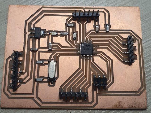
This week I worked on programing the Micro Controller that I have build in Electronics Design Week
Assignment
Individual assignment: - Read a microcontroller data sheet - Program your board to do something, with as many different programming languages and programming environments as possible.
Group assignment: - Compare the performance and development workflows for other architecture. in the Group Page you can find more details.
Requirements:
In order to complete this assignment you need the following:
- Custom made board with micro controller
- Arduino IDE software
- Jumper wires
- USB cable
- FTDI Cable
- Arduino UNO

Datasheet
In order to use any electronics component you need to read and understand the datasheet.
From the datasheet here are some of main features of ATmega328P
- 32K bytes of in-system self-programmable flash program memory
- 1Kbytes EEPROM
- Six PWM channels
- 8-channel 10-bit ADC
- Programmable serial USART
- Master/slave SPI serial interface
- Byte-oriented 2-wire serial interface (Phillips I2C compatible)
- Interrupt and wake-up on pin change
- Six sleep modes: Idle, ADC noise reduction, power-save, power-down, standby, and extended standby
- 23 programmable I/O lines
- Operating voltage: 2.7V to 5.5V
-
Temperature range: –40°C to +125°C
-
It’s very important to know each pin and the functions of it.

Arduino IDE
-
Download and install Arduino IDE from Arduino IDE
-
Start Arduino IDE

Bootloader
In order to program ATMEGA328P we need to burn the Bootloader to the ATMEGA328P. I follow this documentation Arduino as ISP and Arduino Bootloaders in order to burn the bootloader in ATMEGA328P.
-
In Arduino IDE Select “ArduinoISP” from File >> Examples >> ArduinoISP

-
Select “Arduino UNO” from Tools >> Board

-
Select Arduino COM# Port from Tools >> Port

To check the Port Number Connect the USB cable to Arduino UNO and Go to Device Manager of the PC

- Select “Arduino as ISP” from Tools >> Programmer

- Upload ArduinoISP Sketch to Arduino UNO

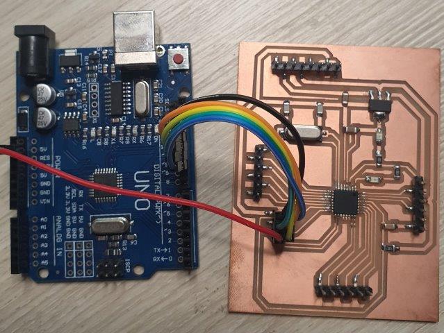
- Wire Arduino UNO board with ISP header of the New board
| Arduino UNO Pin # | New Board ISP Port |
|---|---|
| 12 | 1-MISO |
| 5V | 2-VCC |
| 13 | 3-SCK |
| 11 | 4-MOSI |
| 10 | 5-RST |
| GND | 6-GND |

 - Go to Tools >> Burn Bootloader and wait until “Done burning bootloader”

- Now you ready to program the new ATMEGA328P board
Programming
There are two ways to program ATMEGA328P. Either by ISP programmer or by FTDI cable.
ISP Programmer
For ISP programing I follow this Arduino as ISP Tutorial
- Create new programing sketch in in Arduino IDE and wire the following code.
   int pinLED = 3;
// the setup function runs once when you press reset or power the board
void setup() {
  // initialize digital pin  as an output.
  pinMode(pinLED, OUTPUT);
}

// the loop function runs over and over again forever
void loop() {
  digitalWrite(pinLED, HIGH);   // turn the LED on (HIGH is the voltage level)
  delay(1000);                       // wait for a second
  digitalWrite(pinLED, LOW);    // turn the LED off by making the voltage LOW
  delay(1000);                       // wait for a second
}
 - Go to Sketch and clink on Upload Using Programmer
 - Wait for Done Uploading message and check the board
FTDI Cable
-
I have tried uploading the sketch with FTDI Cable but I got the following Error

-
After long research about this error I found that “Uploading sketch via the programmer will wipe the bootloader”. https://forum.arduino.cc
- I have burned the Bootloader again and I have successfully able to upload the sketch with FTDI cable

C programming
One of the most common Embedded programming language is C and it’s very powerful programming language.
First of all I started with watching this tutorial Learning AVR-C Episode 2: Setup and BlinkLED which is very useful for beginner in embedded C programming.
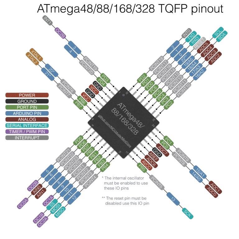
After reading this diagram will use PORT PIN instead of ARDUINO PIN
-
C programming can be done by using Arduino IDE
-
Here is the C code for LED Blink

- Upload the code with FTDI cable and check the board after you got Done uploading message
This is my first code in C and I’m so happy to see it working.
Final Result
Here is the video for the final result
It was very exciting moment when I sea the LED start blinking.
Source code
-
Here the Arduino Code for LED blink Blink2.ino
-
Here the Arduino Code for LED blink Blink_in_C.ino