10. Mechanical design & Machine design
Task: Mechanical Design, Machine Design
Mechanical Design (part 1 of 2)
- Group assignment:
- Design a machine that includes mechanism + actuation + automation
- Build the mechanical parts and operate it manually.
-
Document the group project
-
Individual assignment:
- Document your individual contribution.
Machine Design (part 2 of 2)
- Group assignment:
- Actuate and automate your machine.
- Document the group project
- Individual assignment:
- Document your individual contribution.
Components
Mechanical Components:
For this project we need the following Mechanical components
Electronics Components:
Also I searched for Electronics components that we need for this project.
3D Design & 3D Assembly
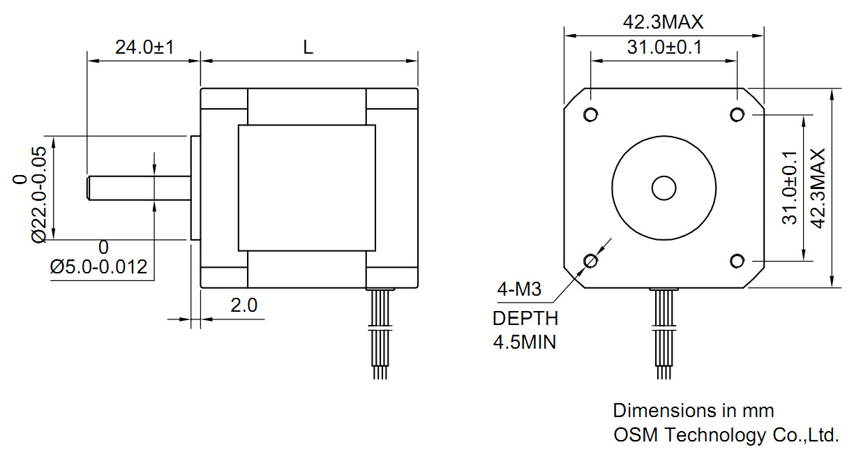
Stepper Motor
- For Stepper Motor we used the NEMA 17 motor and create sketch and 3d Module base on the standard dimensions for NEMA 17 from https://reprap.org/wiki/NEMA_17_Stepper_motor
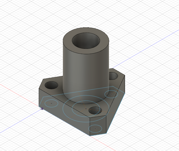
- For the Nut I used Caliper tool to measure the dimensions of the bearing to Design Nut
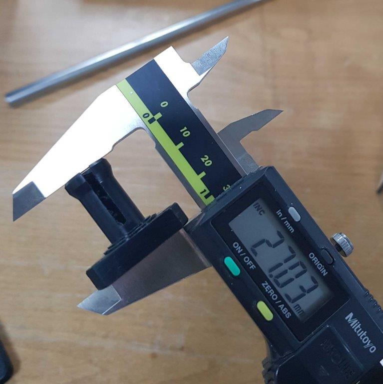
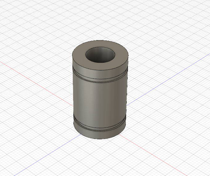
Bearing
- For the bearing I used Caliper tool to measure the dimensions of the bearing
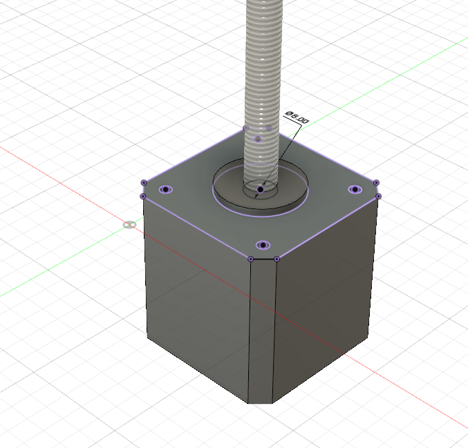
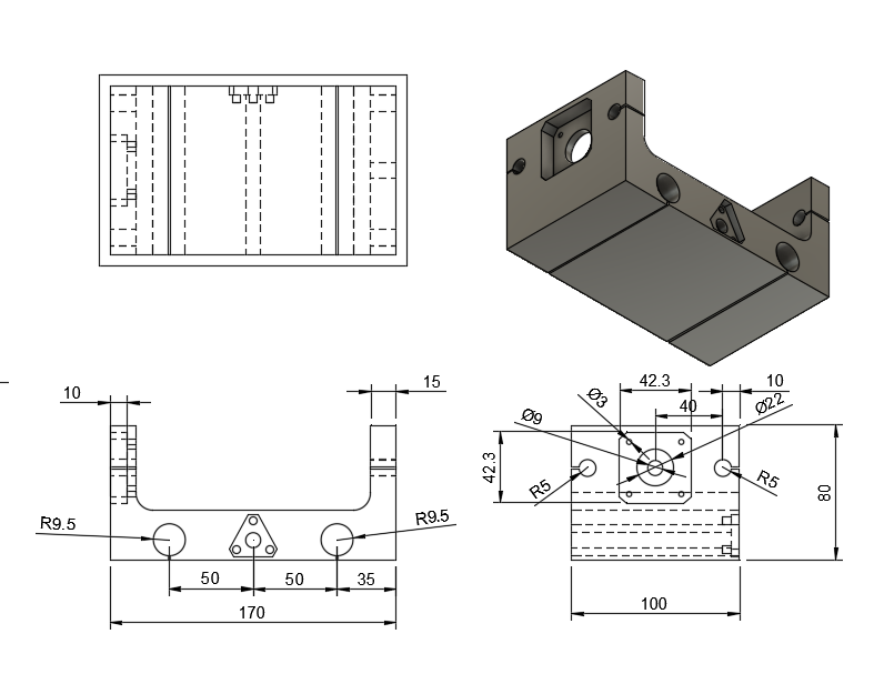
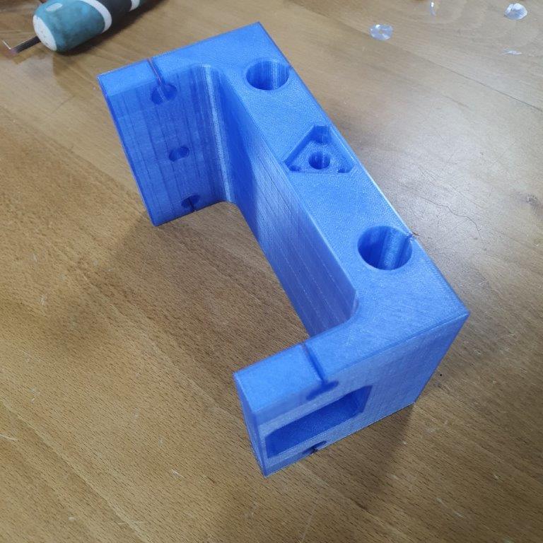
Z-Axis Part
- My part in this project is to design Z-Axis part which will carry the spindle part.
-
3D Assembly
Using Joint tool in fusion 360 to assemble 3D parts together
-First of all I have to assemble Z-Axis part with the spindle holder part.
I found that there is no space for bearing in the spindle holder.
-
Second Assembly after update the spindle holder design
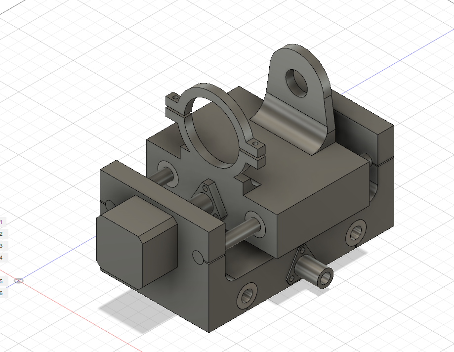
-
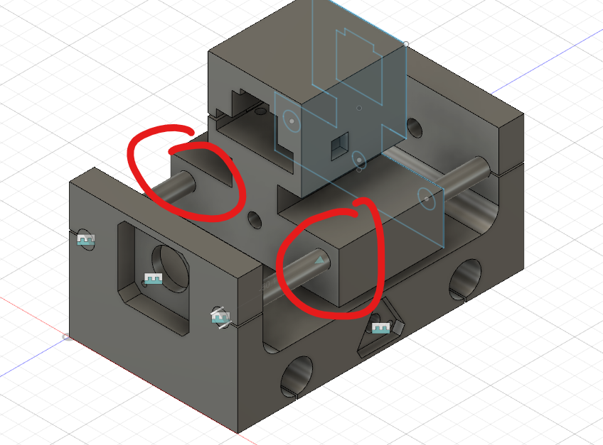
After assembling all parts together, we need to make sure that is no interference between parts by using interference check tools in fusion 360
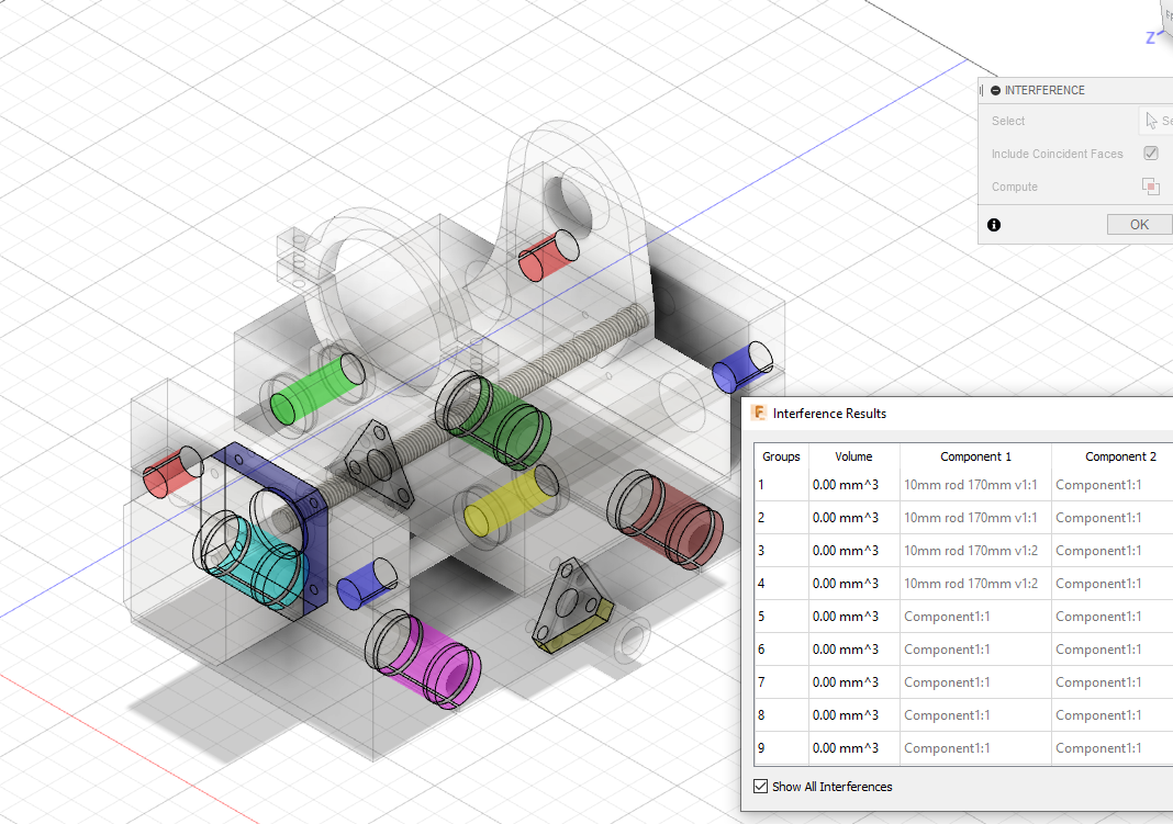
-
Assembling X-Axis parts together
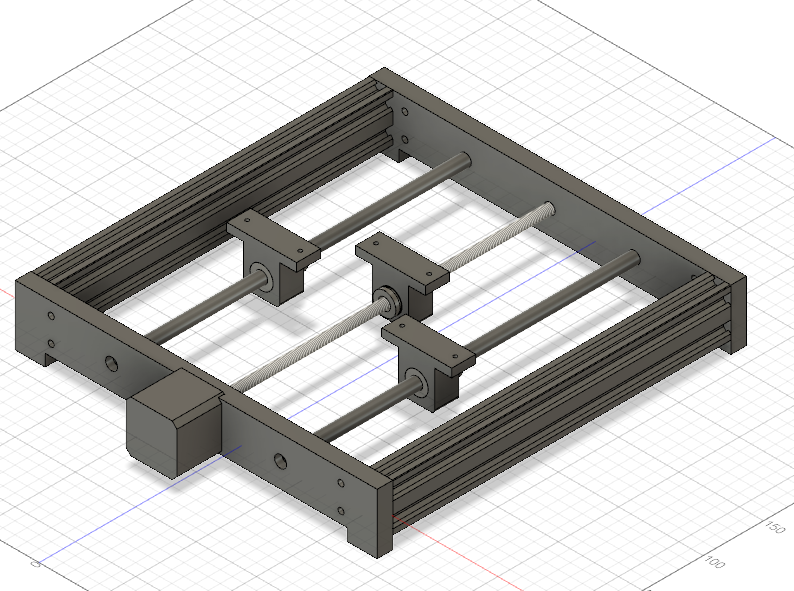
-
Assembling Y-Axis parts together
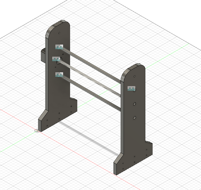
-
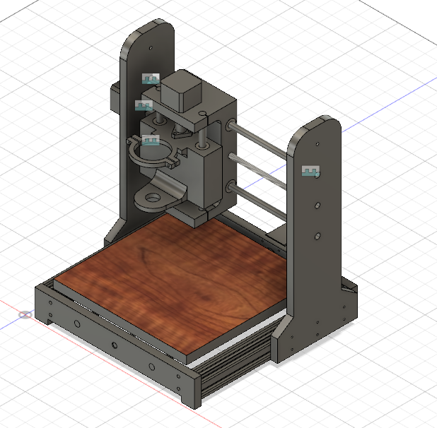
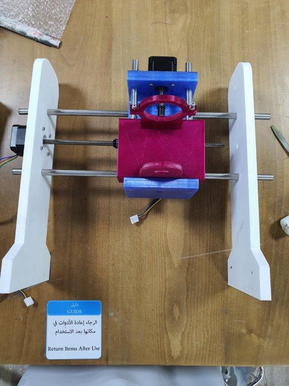
Now to assemble all machine Axis together
3D Printing
For fabricating the part I decided to use 3D printing, because the part is very complicated and can’t be with ShopBot or laser cutting machine.
I used Ultimaker Cura Software and Ultimaker 3 Extended 3D printer.
-
I open the STL file with Ultimaker Cura software and I apply the following setting with support
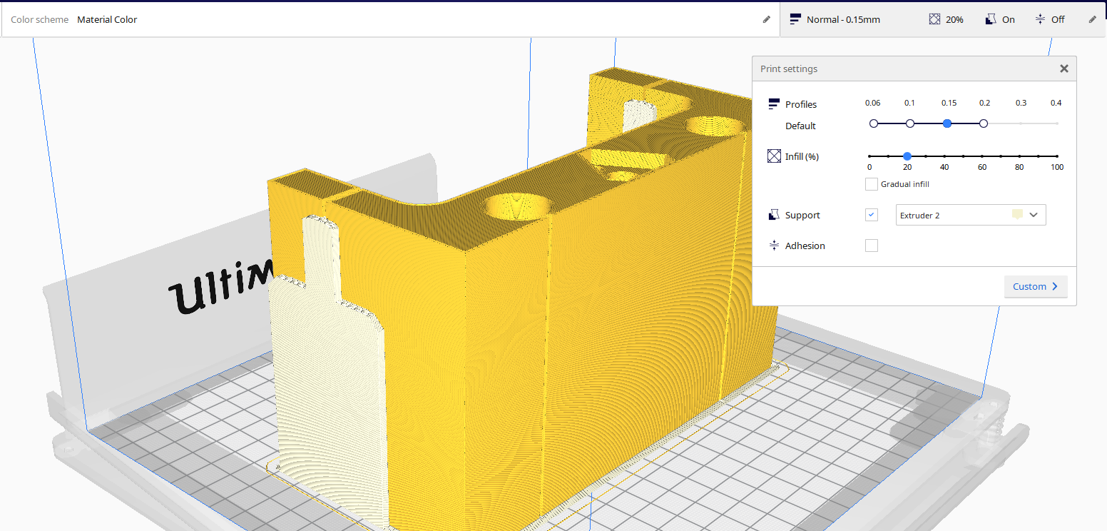
-
The printing failed to print.
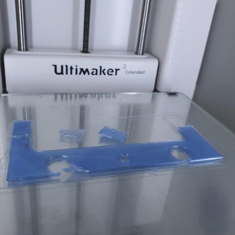
- I change the setting of the printing as following setting without support.
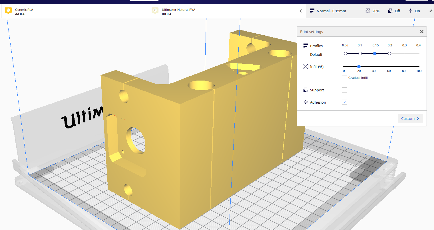
- Also I covert the printer with acrylic sheet to prevent the cold air form the Air-Condition
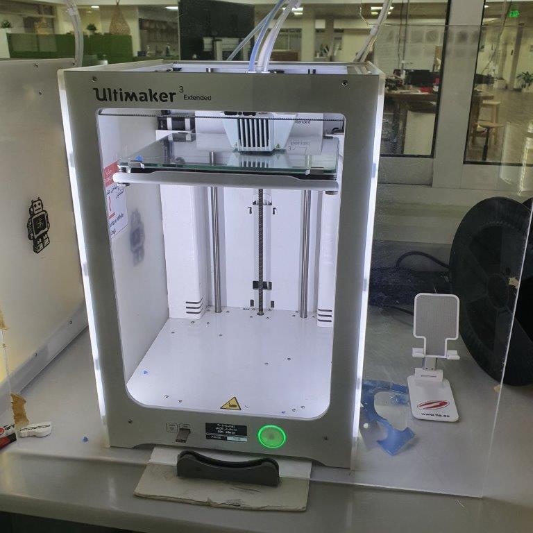
- The part was successfully printed
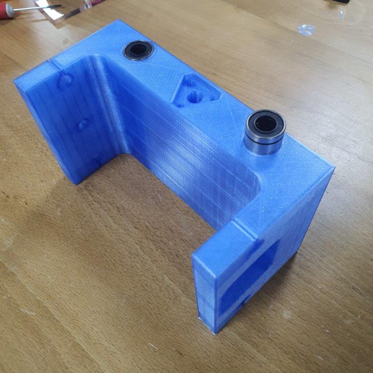
- Insert the bearings
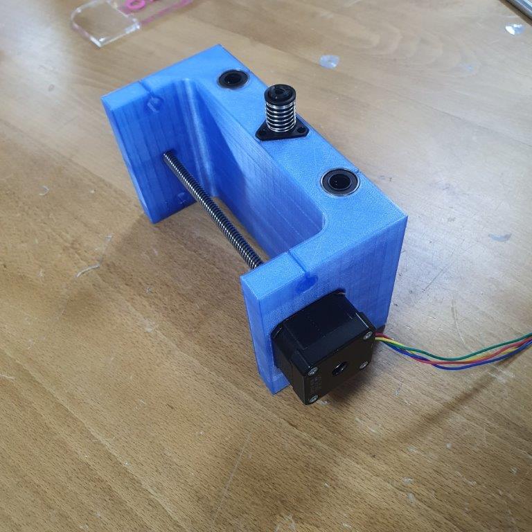
- Insert the motor
Assembly
Here the part after Assembly with anther components
Software
Download Universal Gcode Sender software from github
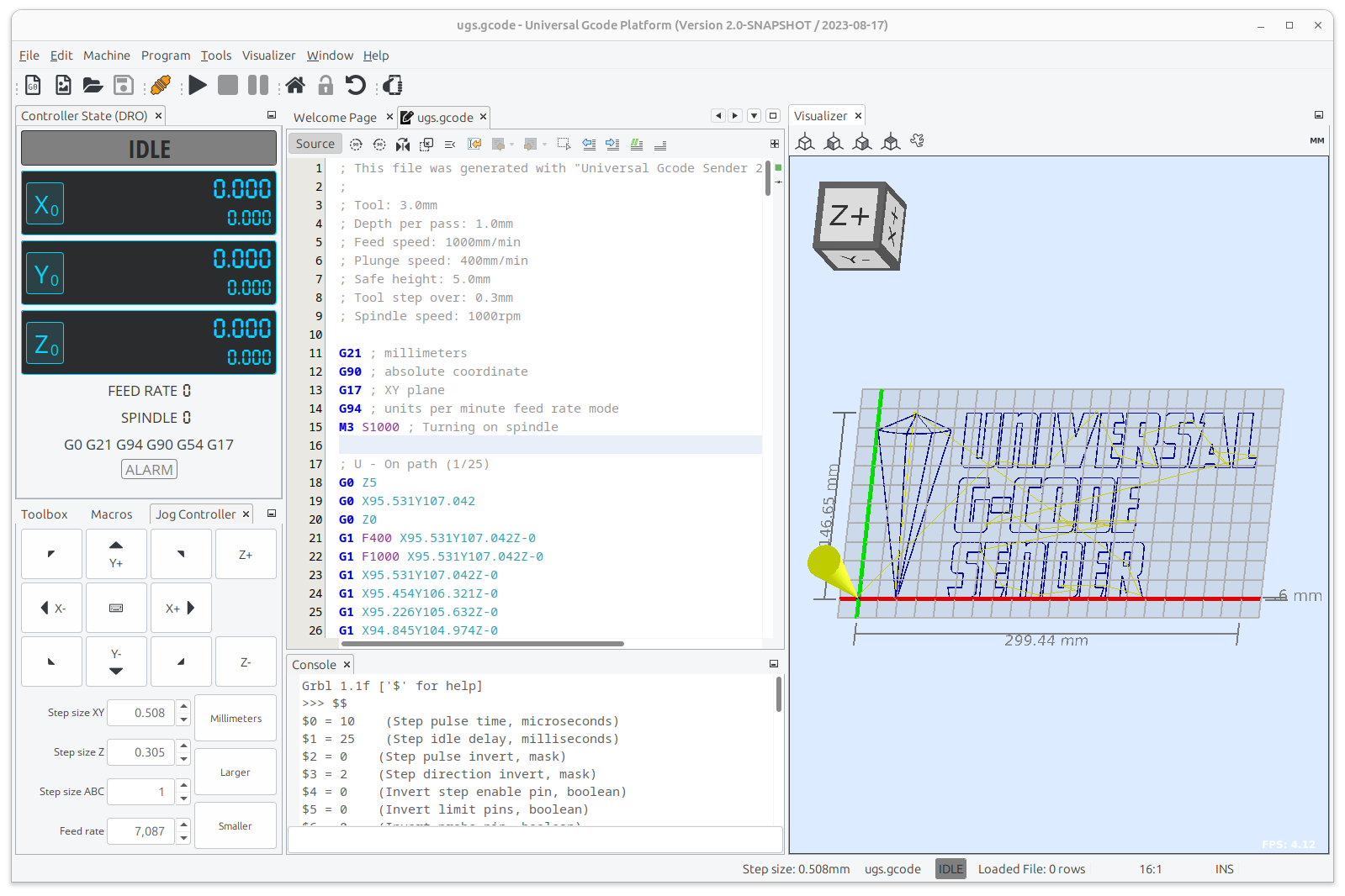
Testing
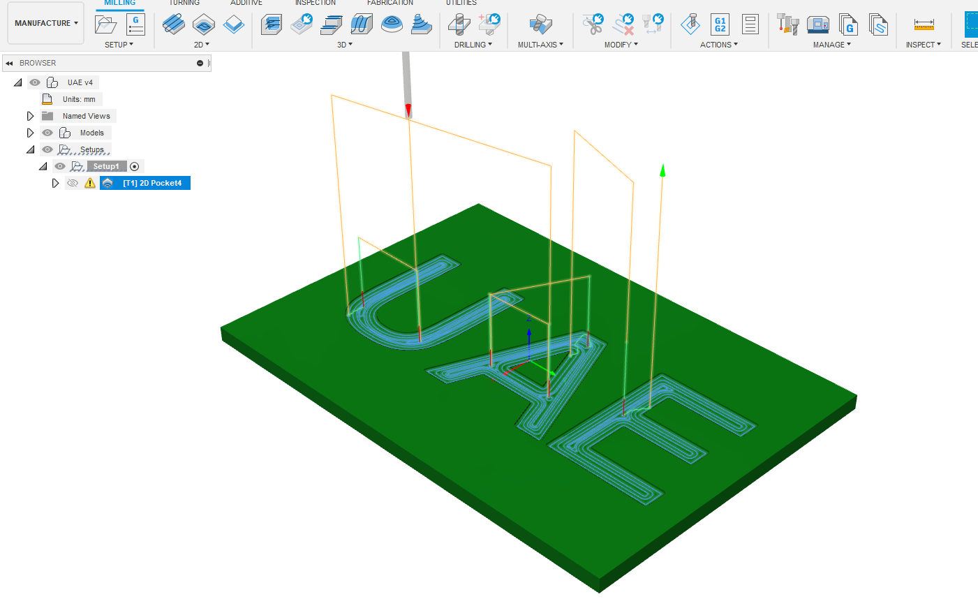
For testing I need to create ToolPath and export G-code to UGS in order to test the machine
Here is very helpful tutorial Making TOOLPATHS and exporting G-CODES | Fusion 360 | Quick Tip
I followed the Tutorial and I made a simple Design and Generate a toolpath using fusion 360
Test 1
To fix this issue I follow this video Fixing Fusion360 GRBL Post Processor
Test 2
Now the machine is working successfully