12. Output devices
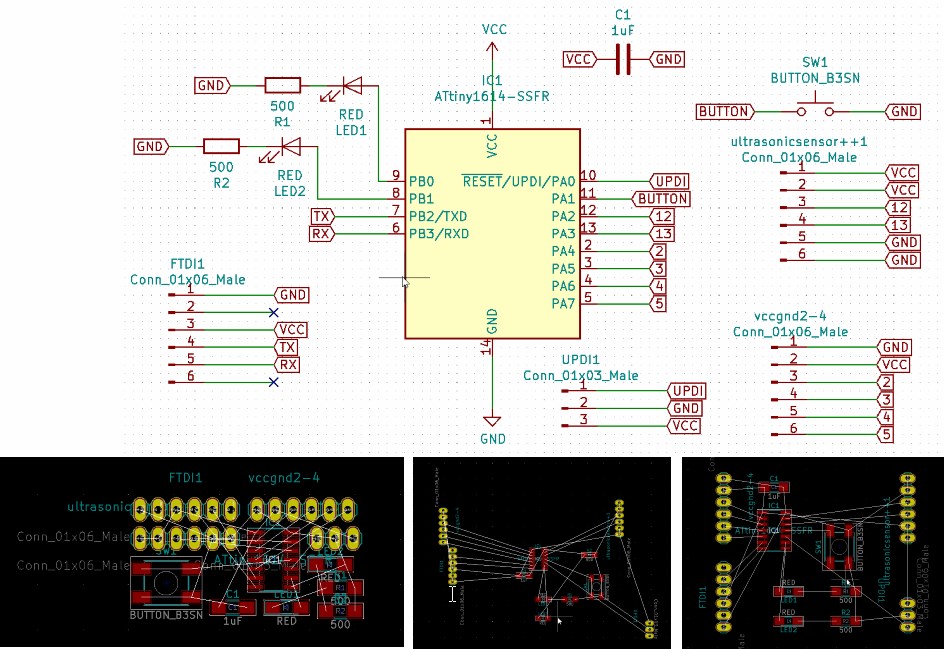
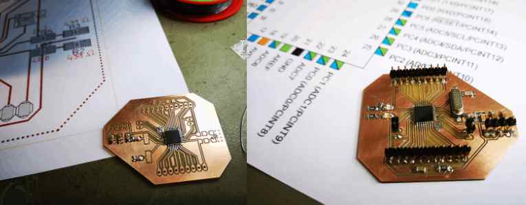
Input LDR output LED with a Attiny 1614-SSFR
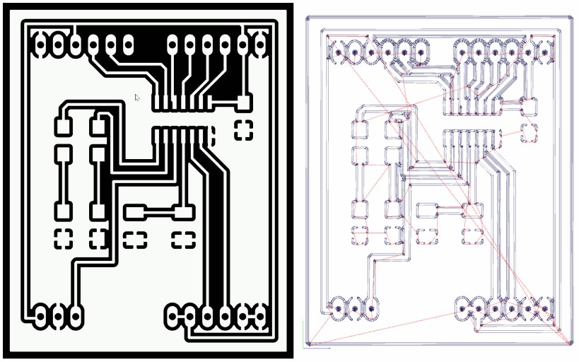
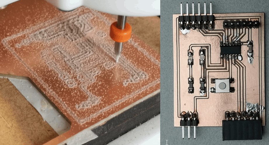
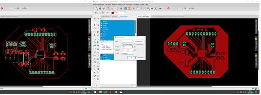
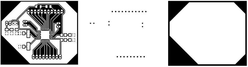
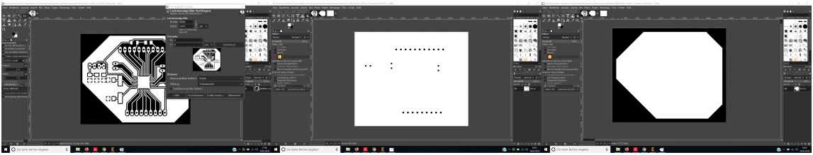
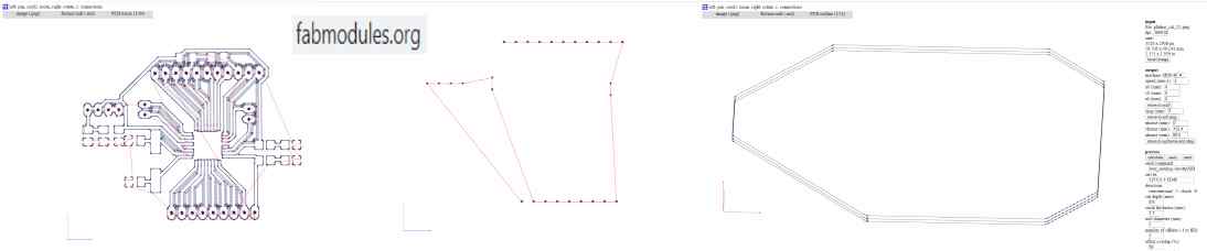
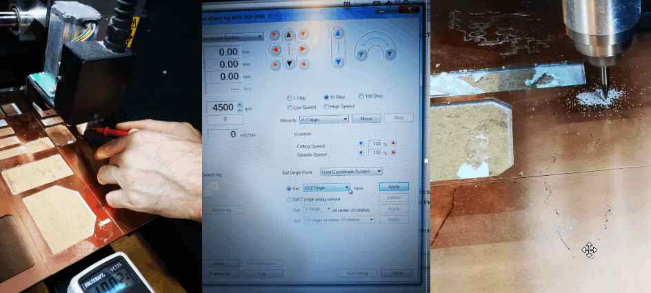
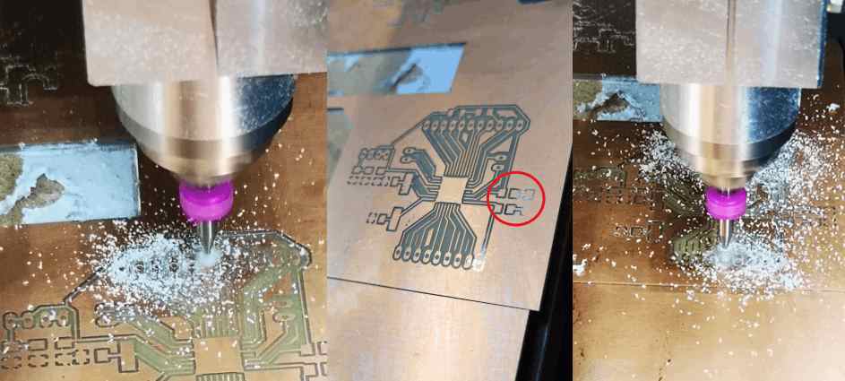
process to make a board => see week 5
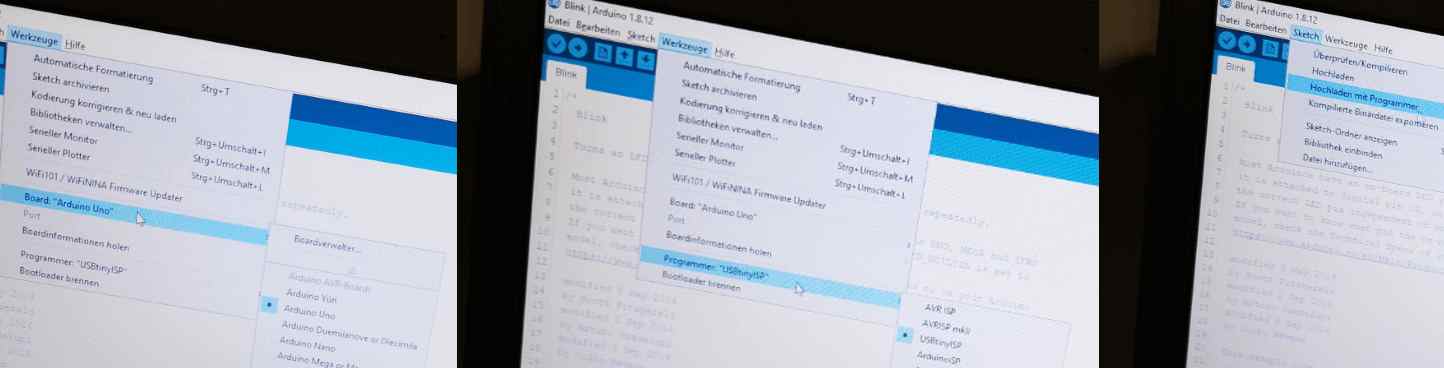
loading the code
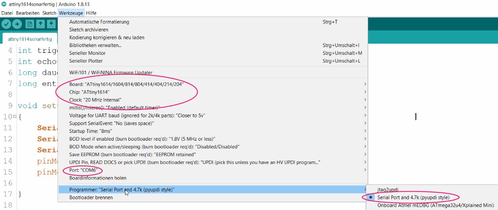
To upload the code I pay attention to this settings.

const int ledPin = 10;

const int ldrPin = 9;

void setup() {

Serial.begin(9600);

pinMode(ledPin, OUTPUT);

pinMode(ldrPin, INPUT);

}

void loop() {

int ldrStatus = analogRead(ldrPin);

if (ldrStatus <= 500) {

digitalWrite(ledPin, HIGH);

Serial.print("Its DARK => Turn on the LED : ");

Serial.println(ldrStatus);

} else {

digitalWrite(ledPin, LOW);

Serial.print("Its BRIGHT => Turn off the LED : ");

Serial.println(ldrStatus);

}

}
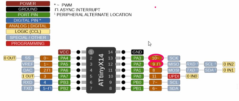
When I want to program in the Arduino IDE I name the pins with the brown colors. In this case 10 for the LED and 9 for the LDR.
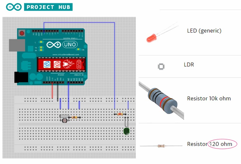
Since I only had a 120 ohm resistor, I tried this one, insted the recommend 220 ohm.
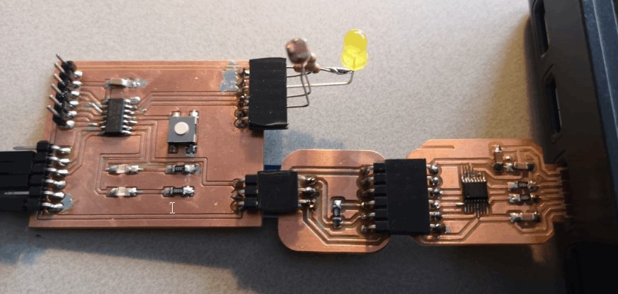
After I adapted everything to my board, I uploaded the code via UPDI
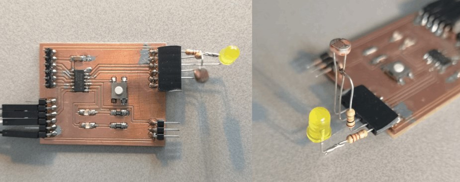
and then the board is connected to the PC via FTDI in order to read out the serial monitor.
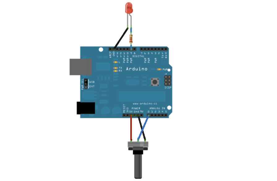
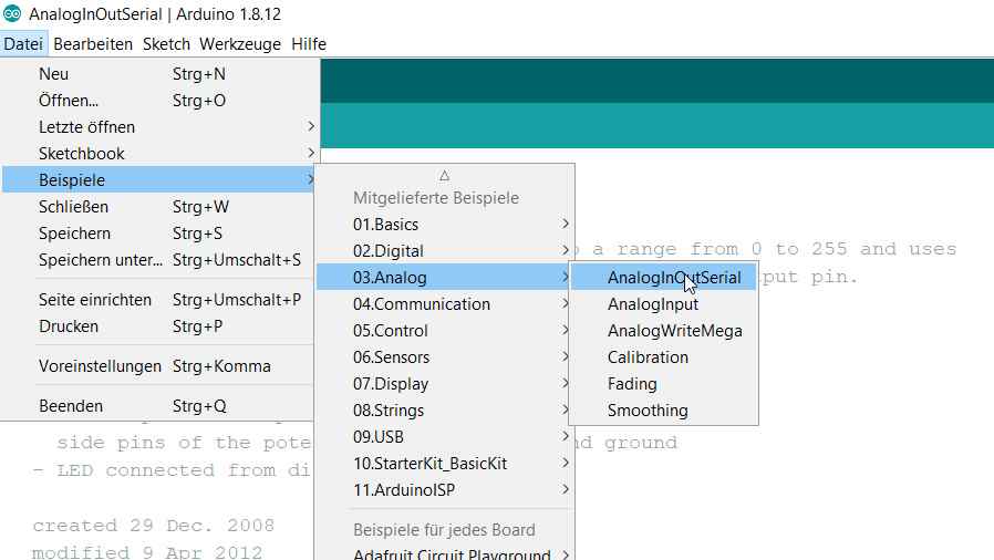
AnalogInOutSerial with with_a_ATMega88-THIN
I would like to design a building site milling machine as the final project. In preparation, I would like to control a spindle and regulate the speed using a potentiometer. Since my knowledge of C ++ is slowly growing, I will first combine different finished solutions on the Arduino to check whether everything works and then transfer this solution to my board from the Electronics Design Week.
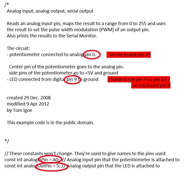
/*
  Analog input, analog output, serial output

  Reads an analog input pin, maps the result to a range from 0 to 255 and uses
  the result to set the pulse width modulation (PWM) of an output pin.
  Also prints the results to the Serial Monitor.

  The circuit:
  - potentiometer connected to analog pin 0.
    Center pin of the potentiometer goes to the analog pin.
    side pins of the potentiometer go to +5V and ground
  - LED connected from digital pin 9 to ground

  created 29 Dec. 2008
  modified 9 Apr 2012
  by Tom Igoe

  This example code is in the public domain.

  http://www.arduino.cc/en/Tutorial/AnalogInOutSerial
*/

// These constants won't change. They're used to give names to the pins used:
const int analogInPin = A0;  // Analog input pin that the potentiometer is attached to
const int analogOutPin = 9; // Analog output pin that the LED is attached to

int sensorValue = 0;        // value read from the pot
int outputValue = 0;        // value output to the PWM (analog out)

void setup() {
  // initialize serial communications at 9600 bps:
  Serial.begin(9600);
}

void loop() {
  // read the analog in value:
  sensorValue = analogRead(analogInPin);
  // map it to the range of the analog out:
  outputValue = map(sensorValue, 0, 1023, 0, 255);
  // change the analog out value:
  analogWrite(analogOutPin, outputValue);

  // print the results to the Serial Monitor:
  Serial.print("sensor = ");
  Serial.print(sensorValue);
  Serial.print("\t output = ");
  Serial.println(outputValue);

  // wait 2 milliseconds before the next loop for the analog-to-digital
  // converter to settle after the last reading:
  delay(2);
}
subject with variation
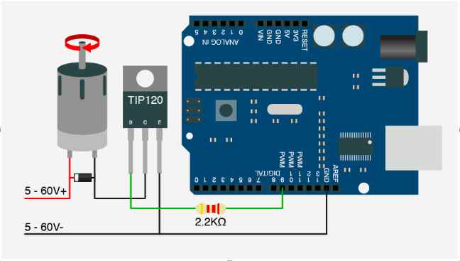
I supplement the original setup with a 9V circuit for the motor and replace the LED with a Mosfet. I now put pin 9 with a 2.2K resistor at the base to pass on the PWM to the motor.
transfer this setting on my board
For the pin arrangement, I used the following example from the fabacademy archive as a guide.
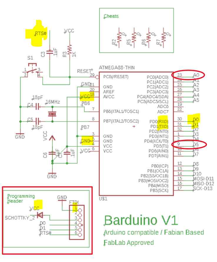
http://archive.fabacademy.org/2018/labs/fablabdassault/students/oyedotun-ajweole/exercise10.html
what pins on my board
I changed the pin assignment as follows.
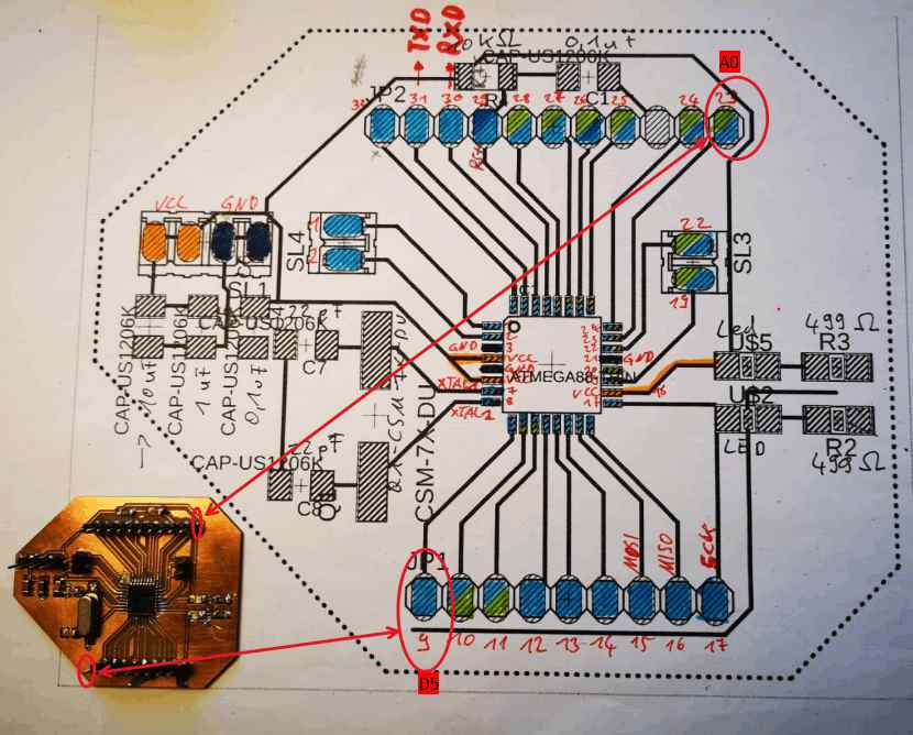
Since it has happened several times that I had to count on 12 unknowns when troubleshooting, the process was easier because I transferred everything and only 3-4 unknowns came into question if something did not work.
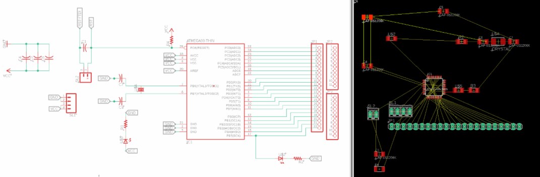
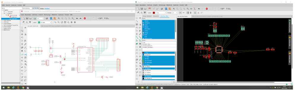
making the board
process to make a board => see also week 5
group
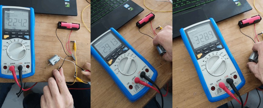
In this example you can see very nicely how the consumption of the amperage increases when you put the motor under load by braking it with your thumb.
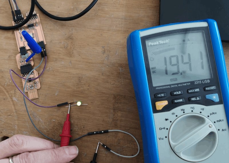
Here we measure the current that is required by the LED to light up. In this case 19.41 mA.
group assignment
Output Devices Group Assignment
files
Board_with_a_ATtiny1614.kicad_pcb
Board_with_a_ATMEGA88.BRD/Eagle
Board_with_a_ATMEGA88.sch/Eagle