3. Computer Aided design
MOI
work environment and workflow
“Moment of Inspiration” is a cad program that works with nurbs.

I start by drawing a quarter of my router so that I can later mirror it in both directions.

With Polyline I first draw the guide rail two-dimensionally in the view.

and then extrude it the length of the 1/4 gantry.

I also use the same instructions to design slide bearings and brackets.
In order to stay a bit clearer, I can assign colors in the browser.

In order to be able to insert a rack into the design, I first draw the floor plan, then extrude it and copy it to the correct length.

I extrude this

and copy it to the correct length.
Even with these few commands, the workflow becomes readable. The commands are clearly arranged and constructing is fun (for me).
Since it would go beyond the scope of documenting the entire process, I will only show some intermediate results.
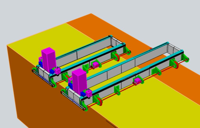
MOI final projekct cad sketches
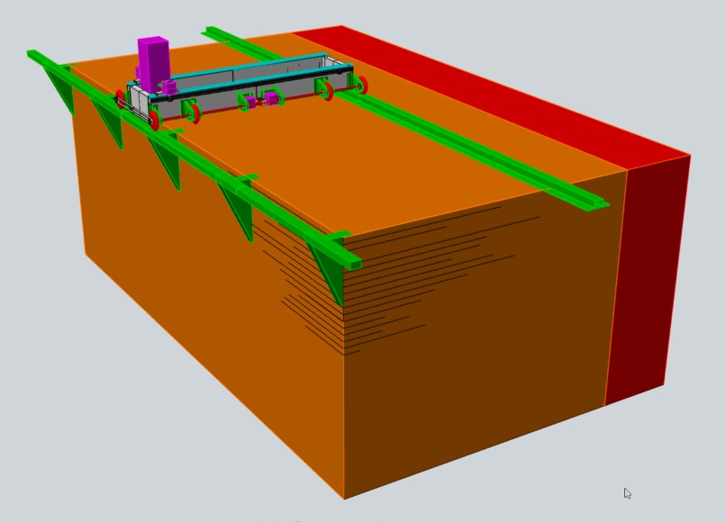
First CAD drawings in which direction the implementation of the sketched ideas could go.
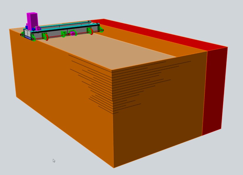
The marked area in the front shows the working area of the milling.
The two behind it are common plate sizes.
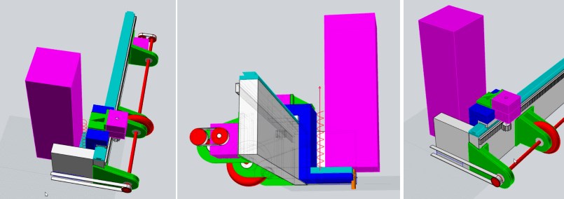
closed rolling gantry
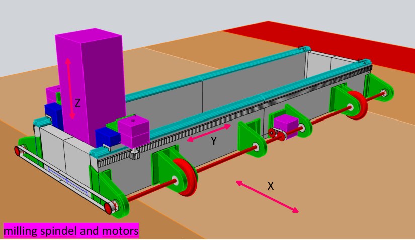
The gantry is a closed box in which the milling spindle in this case is moved on the Y-axis via a rack, gear wheel and guide rail.
The Y axis is guided with fixed wheels on a bearing axis.
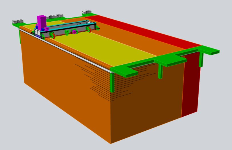
mill beyond the panel edge
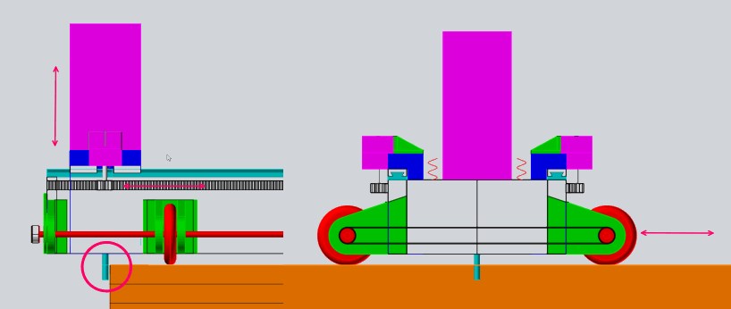
An interesting option is certainly to let the milling cutter run the panel edge.
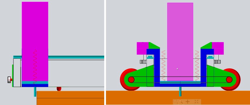
in this way, the material can also be cut beyond the long sides.
problems with pockets
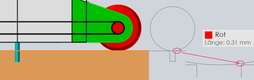
With the drive in this form, pockets can only be milled in the places where no wheels run over the wooden materials.
Simple 8-10 mm grooves should simply be rolled over.
I first drew the cnc milling machine as a quarter and then mirrored it. It may well be that I can get there with fewer motors and toothed belts.
theme with variation
However, a rail system for the guide could also be exciting, which e.g. would be screwed on or put on and could be adjusted more precisely in order to also be able to mill bags.
It would also be easier to find starting points for milling the 2nd path or the other half.
Or something like a start and end ramp. With which you can adjust the tracks exactly at the starting point.
It is also possible to build the milling machine / gantry as long as you need it.
Since the gantry is not expensive, it is best to have one for every width.
It would also be good to be able to shift the roles and maybe have more than 4. This would make milling pockets possible again.
A tool change would also be conceivable.
Fusion 360
x-axis-wheels
With Fusion 360 I would like to start with the x axis.
Since the wheels are supposed to be fixed, I have to remove the ball bearings and install lockable wheel mounts on the right and left instead.
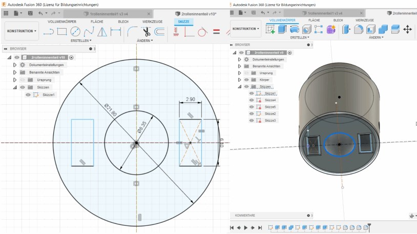
I start with a sketch, which I later extrude and from which I subtract further extruded bodies.
Later I’ll round off the edges.
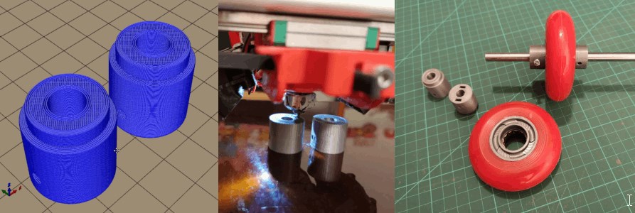
Now I download the stl file, print it and do a first test.
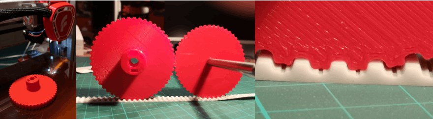
x-axis-gears optional
Since it would be possible to bring 2 drive systems directly on one axis, or to swap the axes quickly, I would like to try a T5 toothed belt or T5 gear.

To do this, I create a new sketch and draw half of the T5 tooth. If I need to adjust the width or height of the teeth, I create parameters. I mirror this

to arrange it around with the correct spacing.

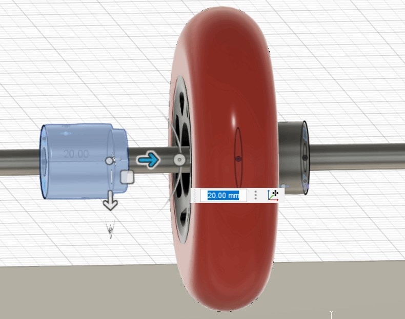
Now I extrude the shape and cut out the hole for the axis. Then I add the component that enables me to fix the gear on the axle.

I put it in the right position,

download the stl file, create the g-code and print it out.
Silhuette studio
Since we at silhuette have some cutting plotters in the FabLab, it makes sense for me to deal with the drawing software of this machine.

First I choose a pictogram that I could use for our new school fablab.
Here I am looking at “theounproject.com”.
But I won’t download the vector file because I want to test the tracing functions in Sihouette.

I take a detailed screenshot and copy the bild.jpg onto the workspace.
tracing

Now I choose the area to trace.

Now I click on trace and the edges of the pixel drawing are now vectors.
I can now click on the picture (.jpg) and drag it away.

I can also display the vector points and reduce them to the most necessary.
change Something

To clean them up or to change them, I have to break the linked path.

Now I could adapt the drawing to my needs and send it directly to the cutting plotter from this program.
Inkscape
In the long run it will also be good to deal with inkscape, as it is very well suited for creating vector files and in most cases I need these as a basis for sending work orders to machines. I am thinking here of the laser cutter in particular.

Same attempt in inkscape.
I copy the .jpg into the workspace.
tracing

I can now trace this way.

Now I can remove the .jpg

and to see the vectors must switch off the filling and switch on the color of the contour.
change Something

Now I can disassemble the path again and then switch on the vector points.

I could now select the Bezier curves to change it.
files for download
Useful links

Dieses Werk ist lizenziert unter einer Creative Commons Namensnennung - Nicht-kommerziell - Weitergabe unter gleichen Bedingungen 4.0 International Lizenz.