11. Input devices
HC-SR04
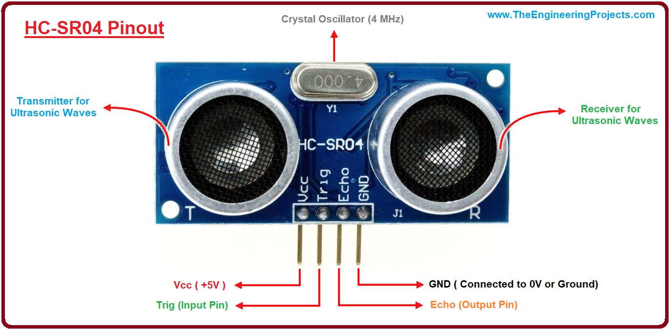
I decided to use the ultrasonic sensor HC-SR04.
The ultrasonic sensor sends ultrasonic bursts and mesures the time difference of the signal comming back. I used the examples from Arduino:
https://www.arduino.cc/reference/en/libraries/hcsr04-ultrasonic-sensor/
pinout
limitations
The HC-SR04 can measure distances of up to 400cm with a tolerance of 3 mm. There might be problems if the signal is deflected away from the sensor. So I have to keep this in mind when using it.
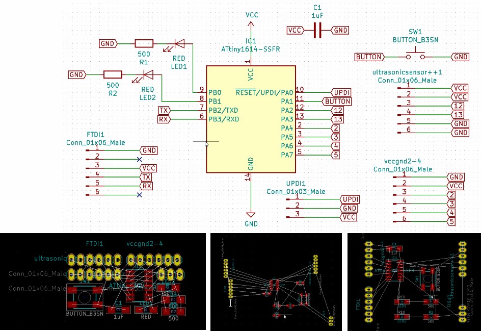
ultasonic sensor with a Attiny 1614-SSFR
process to make a board => see week 5
loading the code for the ultrasonic sensor on the board
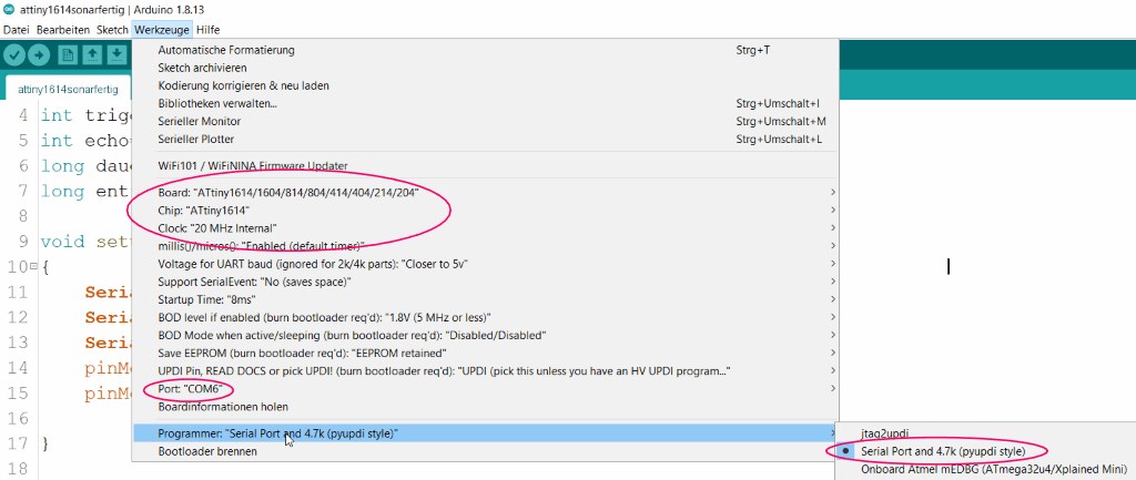
To upload the code I pay attention to the following settings.
int ledPingruenzwei=6;
int ledPingruen=7;
int trigger=9;
int echo=10;
long dauer=0;
long entfernung=0;
void setup()
{
Serial.pins(5, 4); //Add this line, before Serial.begins()
Serial.begin(115200);
Serial.println("start");
pinMode(trigger, OUTPUT);
pinMode(echo, INPUT);
}
void loop()
{
//Serial.print("Hello");
digitalWrite(trigger, LOW);
delay(5);
digitalWrite(trigger, HIGH);
delay(10);
digitalWrite(trigger, LOW);
dauer = pulseIn(echo, HIGH);
entfernung = (dauer/2) / 29.1;
if (entfernung >= 500 || entfernung <= 0)
{
Serial.println("no reading possible => both green leds");
digitalWrite(ledPingruenzwei, HIGH);
delay(1000);
}
else
{
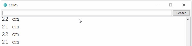
Serial.print(entfernung);
Serial.println(" cm");
digitalWrite(ledPingruenzwei, LOW);
digitalWrite(ledPingruen, HIGH);
}
delay(1000);
}
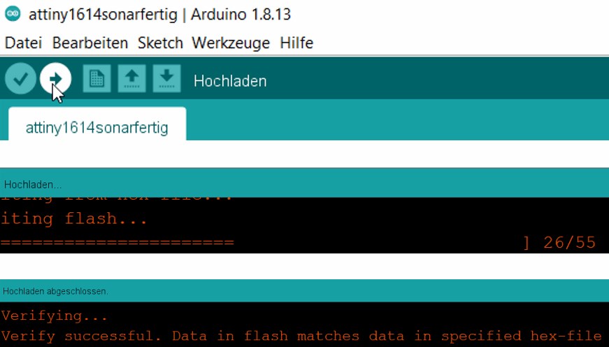
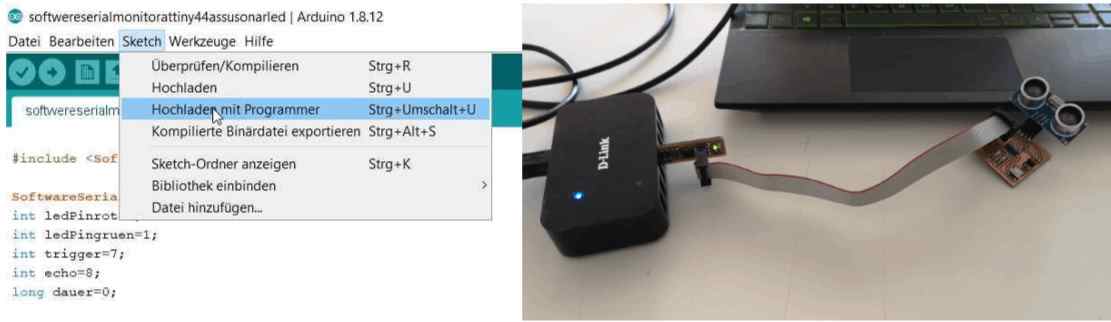
now I upload the sketch via the UPDI interface.
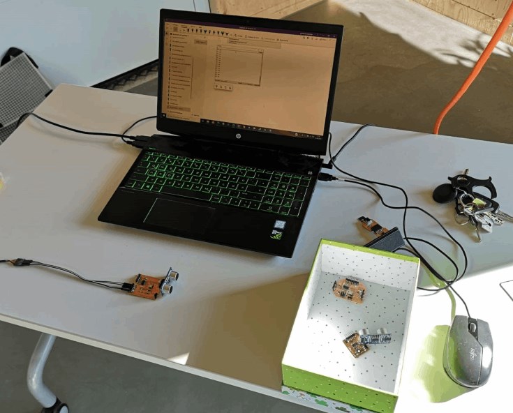
reading out the data via the serial monitor
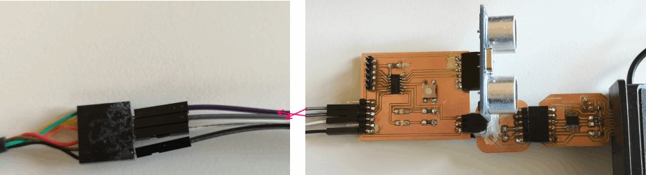
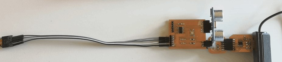
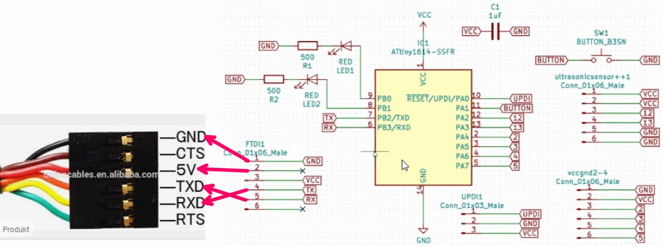
On the other side of the board at the FTDI interface, I connect the tx of the board with the rxd of the ftdi cable and the rx of the board with the txd of the cable in order to be able to read out the data from the serial monitor.
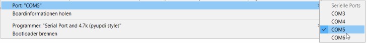
After uploading the sketch, I connect the FTDI cable to a USB port, select it (COM5)
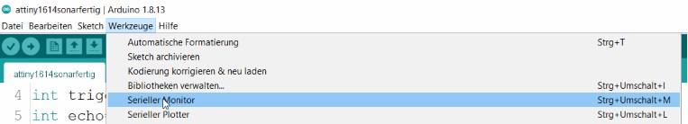
and start the serial monitor. Here it is important, that the same baudrate is set as in the sketch.
ultrasonic sensor board with_a_ATtiny44-SSU
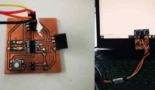
making process
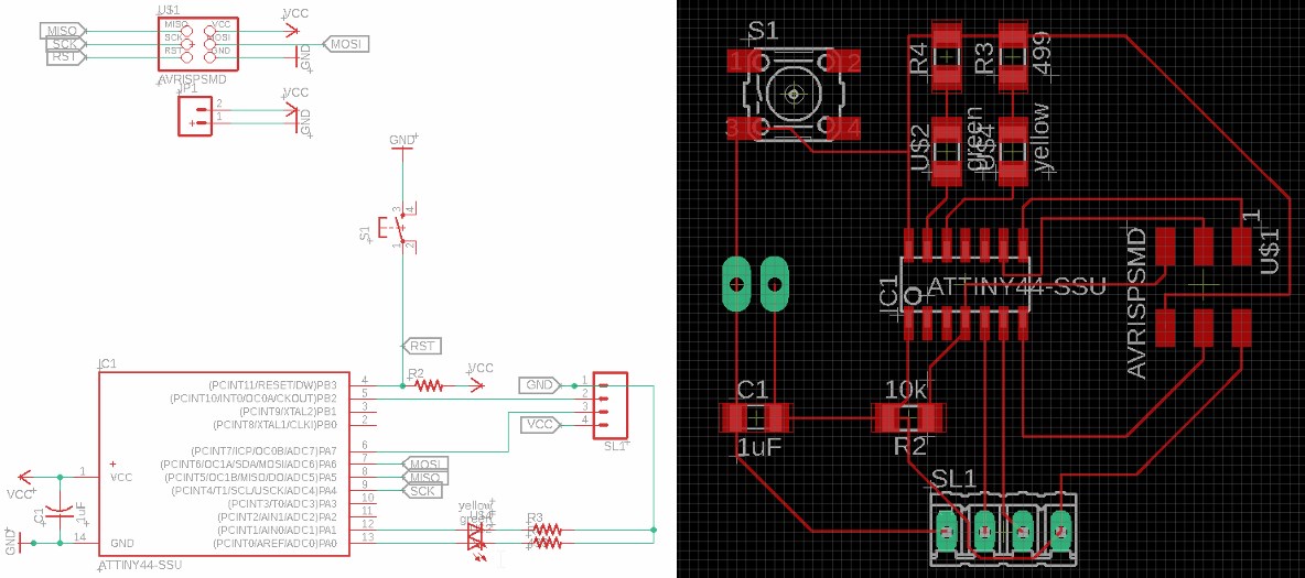
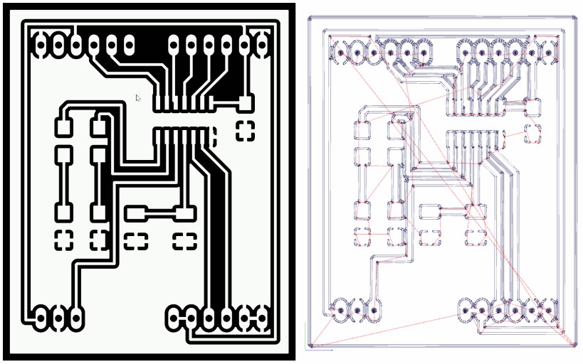
In order to try out the ultrasonic sensor, I first drew a new board according to the design rules described in weeks 5 and 7.
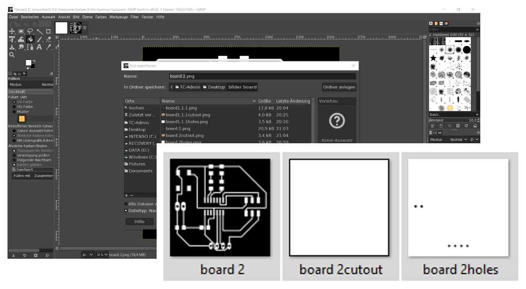
In Gimp I prepared the PNG files for use in Fab Modules
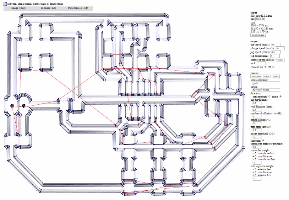
and created the gcode in Fab Modules.
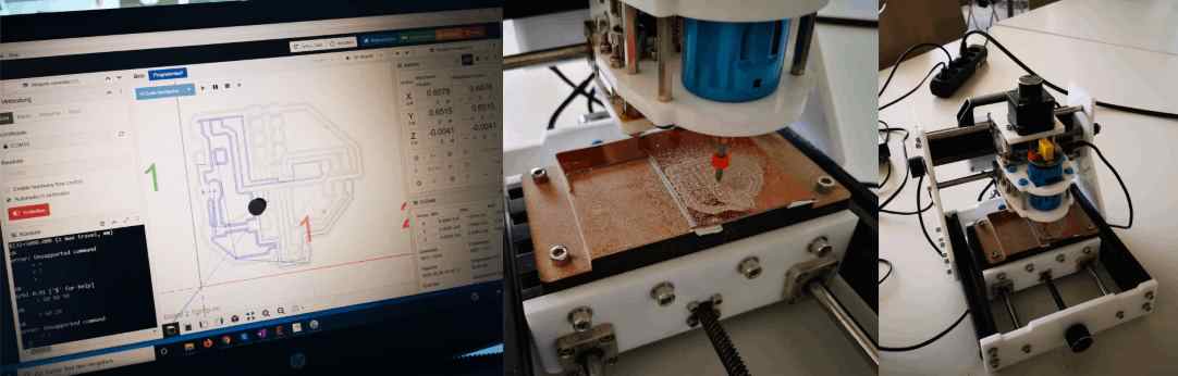
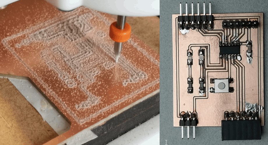
Now I have milled the pcb with CNCjs.
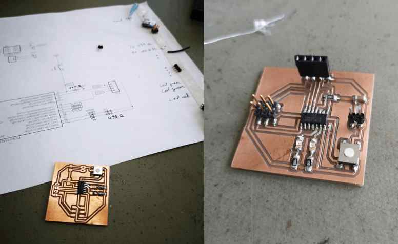
After soldering....
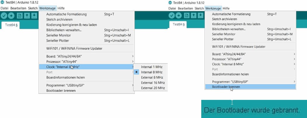
I burned the bootloader.
programming
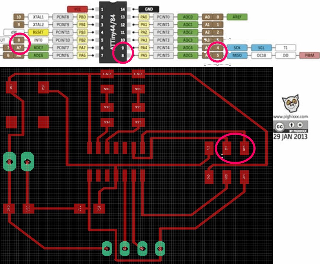
In order to be able to read the Attiny 44A SSU with the serial monitor, I have to stretch over the FTDI cable connection and reprogram SCK and MISO to RX and TX. The serial monitor should help me to set the LEDs like this. That they glow green in the specified functional area and glow red in the areas where it is no longer optimal. So pins 8 and 9 must serve as RX and TX.
Code Example
#include <SoftwareSerial.h>

SoftwareSerial mySerial(4, 5); // RX, TX
int ledPinrot=0;
int ledPingruen=1;
int trigger=7;
int echo=8;
long dauer=0;
long entfernung=0;

void setup()
{

    mySerial.begin(9600);
    mySerial.println("start");
    pinMode(trigger, OUTPUT);
    pinMode(echo, INPUT);

}

void loop()
{

    digitalWrite(trigger, LOW);

    delay(5);
    digitalWrite(trigger, HIGH);

    delay(10);
    digitalWrite(trigger, LOW);

    dauer = pulseIn(echo, HIGH);

    entfernung = (dauer/2) / 29.1;


    if (entfernung >= 500 || entfernung <= 0)
{
    mySerial.println("no reading possible RED LED");
    digitalWrite(ledPinrot, HIGH);
 delay(1000);
}
else
{
    mySerial.print(entfernung);
    mySerial.println(" cm");
    digitalWrite(ledPinrot, LOW);
    digitalWrite(ledPingruen, HIGH);

}
delay(1000);
}
group assignment
In this example looks how the voltage transmission in the LDR changes when the light hits it in different intensities.
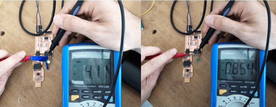
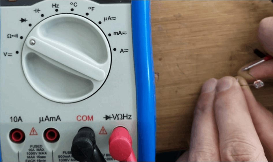
Now we measure the el. Resistance of the ldr.
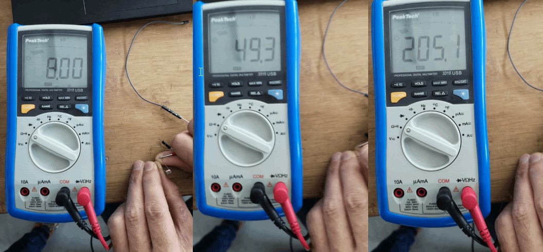
From left to right, the ldr is darkened more and more. The electrical resistance increases with the degree of darkening.
files
sonarboard_with_a_ATtiny1614.kicad_pcb
sonarboard_with_a_ATiny1614.sch
sonarboard_with_a_ATtiny44-SSU.brd
sonarboard_with_a_ATtiny44-SSU.sch