9. Embedded programming
preparations to program board 1 with the Attiny 1614
To be able to program the board with the Attiny, I have to make various settings and add a library.
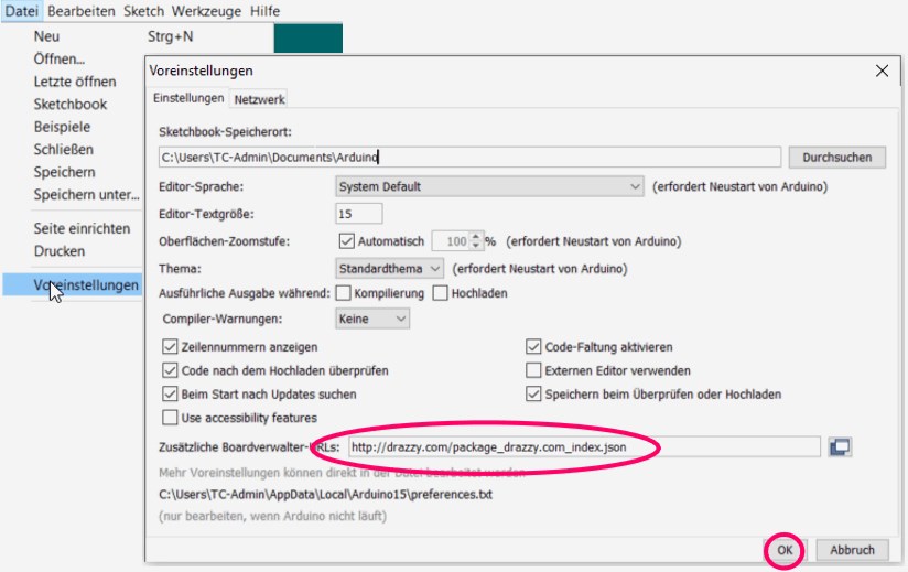
Here I add the following link at the marked place. http://drazzy.com/package_drazzy.com_index.json

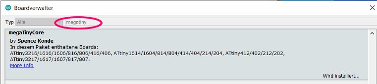
Now I go to the board manager, enter megatiny in the search bar and install the mega tiny core library from Spencer Konde.
To test the board I use the code Blink from the website learn.adafruit.com.
upload blink to test
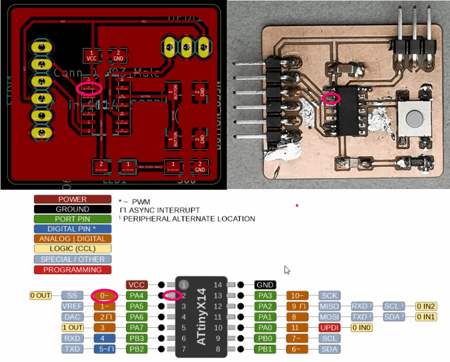
In order to be able to upload Blink I have to find out which pin is connected to the LED and selectively control it. In the Arduino programming environment, I have to insert a 0 into the sketch for pin 2.
/*
  Blink
  Turns on an LED on for one second, then off for one second, repeatedly.

  This example code is in the public domain.
 */

 //I only change the pin to which the LED on the ATtiny 1614 is connected.

int led = 0;

// the setup routine runs once when you press reset:
void setup() {
  // initialize the digital pin as an output.
  pinMode(led, OUTPUT);
}

// the loop routine runs over and over again forever:
void loop() {
  digitalWrite(led, HIGH);   // turn the LED on (HIGH is the voltage level)
  delay(1000);               // wait for a second
  digitalWrite(led, LOW);    // turn the LED off by making the voltage LOW
  delay(1000);               // wait for a second
}
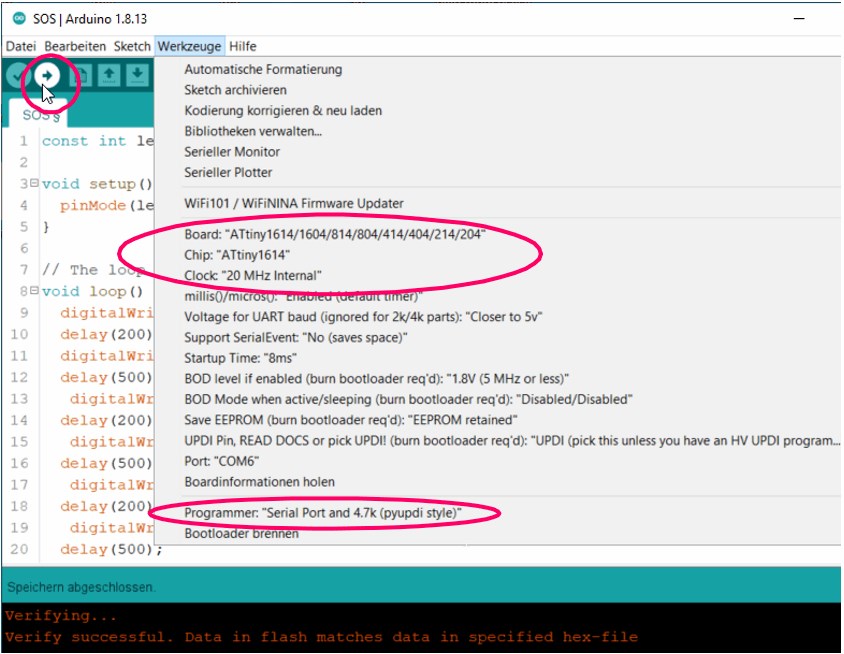
With the following settings I upload the sketch via the updi interface of the programmer.
SOS => arduino code
Theme with variation. After the first relief that everything seems to work, I change the code so that one SOS light signal is played repeatedly.
const int led = 0; // Declare constant "led" to the pin where the LED is connected

void setup() {
  pinMode(led, OUTPUT); // Set LED as an output
}

// The loop function runs over and over
void loop() {
digitalWrite(led, HIGH); // Turn the LED on (HIGH is the voltage level)
  delay(200);             // wait for 0,2 seconds
  digitalWrite(led, LOW);  // Turn the LED off (by making the voltage LOW)
  delay(500);             // Wait for 0,5 seconds
   digitalWrite(led, HIGH);
  delay(200);
   digitalWrite(led, LOW);
  delay(500);
   digitalWrite(led, HIGH);
  delay(200);
   digitalWrite(led, LOW);
  delay(500);


digitalWrite(led, HIGH);
  delay(1000);
  digitalWrite(led, LOW);
  delay(500);
   digitalWrite(led, HIGH);
  delay(1000);
   digitalWrite(led, LOW);
  delay(500);
   digitalWrite(led, HIGH);
  delay(1000);
   digitalWrite(led, LOW);
  delay(500);


 digitalWrite(led, HIGH);
  delay(200);
  digitalWrite(led, LOW);
  delay(500);
   digitalWrite(led, HIGH);
  delay(200);
   digitalWrite(led, LOW);
  delay(500);
   digitalWrite(led, HIGH);
  delay(200);


  digitalWrite(led, LOW);
  delay(2500);
}
SOS => tinkercad blocks
In the next step I try to program an SOS light signal for the led with tinkercad blocks.
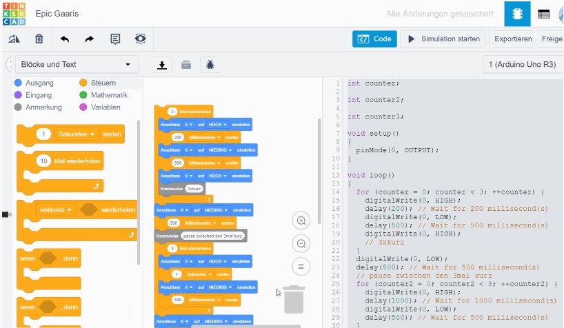
While I select the blocks, put them together and assign values to them, I can display the code in Arduino language in the side window. For a bloody beginner like me, to whom programming is very alien, comparatively fun.
int counter;

int counter2;

int counter3;

void setup()
{
  pinMode(0, OUTPUT);
}

void loop()
{
  for (counter = 0; counter < 3; ++counter) {
    digitalWrite(0, HIGH);
    delay(200); // Wait for 200 millisecond(s)
    digitalWrite(0, LOW);
    delay(500); // Wait for 500 millisecond(s)
    digitalWrite(0, HIGH);
    // 3xkurz
  }
  digitalWrite(0, LOW);
  delay(500); // Wait for 500 millisecond(s)
  // pause zwischen den 3mal kurz
  for (counter2 = 0; counter2 < 3; ++counter2) {
    digitalWrite(0, HIGH);
    delay(1000); // Wait for 1000 millisecond(s)
    digitalWrite(0, LOW);
    delay(500); // Wait for 500 millisecond(s)
  }
  digitalWrite(0, LOW);
  delay(500); // Wait for 500 millisecond(s)
  for (counter3 = 0; counter3 < 3; ++counter3) {
    digitalWrite(0, HIGH);
    delay(200); // Wait for 200 millisecond(s)
    digitalWrite(0, LOW);
    delay(500); // Wait for 500 millisecond(s)
  }
  digitalWrite(0, LOW);
  delay(3000); // Wait for 3000 millisecond(s)
}
programm bord 2 with a ATtiny44-SSU
load the bootloader with brians programmer
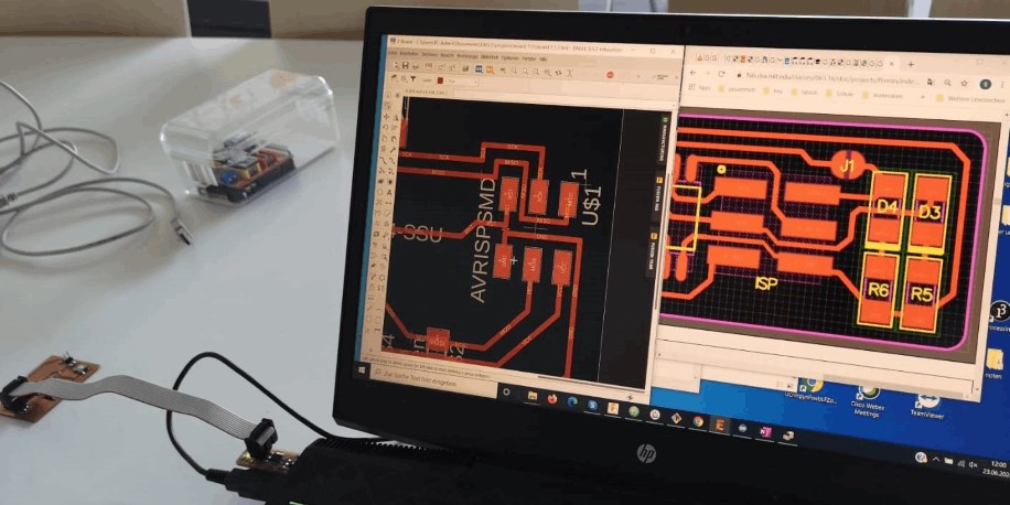
I open the board of Brian’s programmer and the board I just created and connect it to the correct ISP headers.
Next I connect the programmer to the usb port on my pc.
It would be better to use an extension, as it can happen that the usb connection on my pc is damaged if there is a faul.
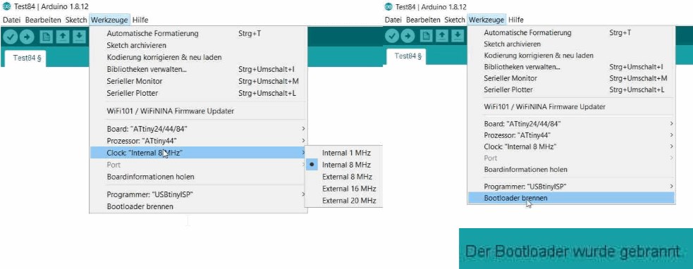
Next I burn the bootloader to program the board in the next step.
load a arduino sketch on the board
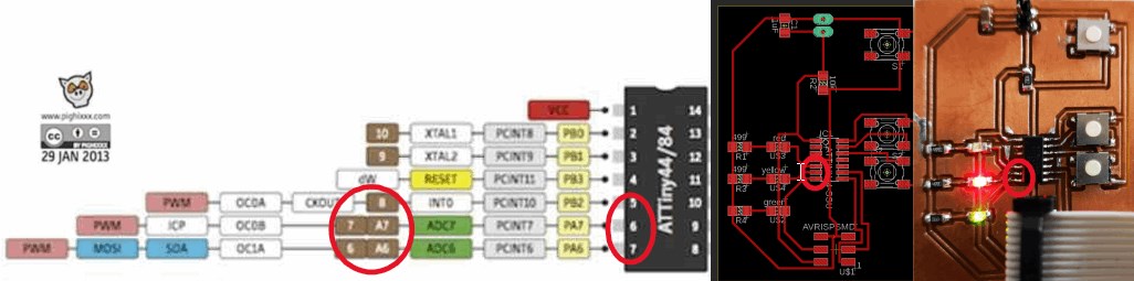
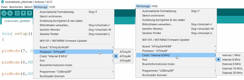
In order to be able to program the board, I have to look which pins I want to lay, or which pins are suitable for what. I put the leds on the pins 5, 6, and 7. in the Arduino IDE these correspond to pins 6, 7 and 8.
void setup()
{

pinMode(7, OUTPUT);

pinMode(8,OUTPUT);

pinMode(6,OUTPUT);

}

void loop()

{

digitalWrite(7, HIGH);

digitalWrite(6, HIGH);

delay(1000);
digitalWrite(7, LOW);

digitalWrite(8, HIGH);

delay(1000);

digitalWrite(8, LOW);
}
}
I have to pay attention to this when writing the program.
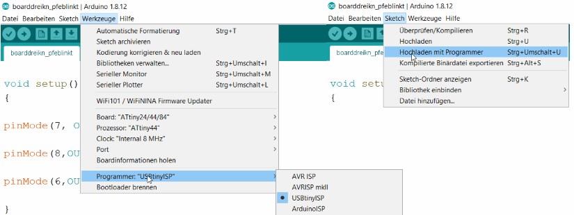
The program is uploaded via the Arduino IDE.
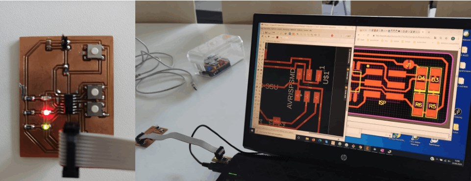
One LED starts to shine continuously and two flash alternately.
datasheet
differences ATtiny 1614 - ATtiny 44
Since I used both, old and new ATtinys in this assignment, I would like to shows the biggest differences between the processors, which are about 13 years apart.
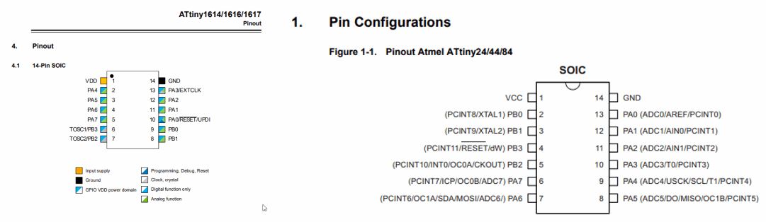
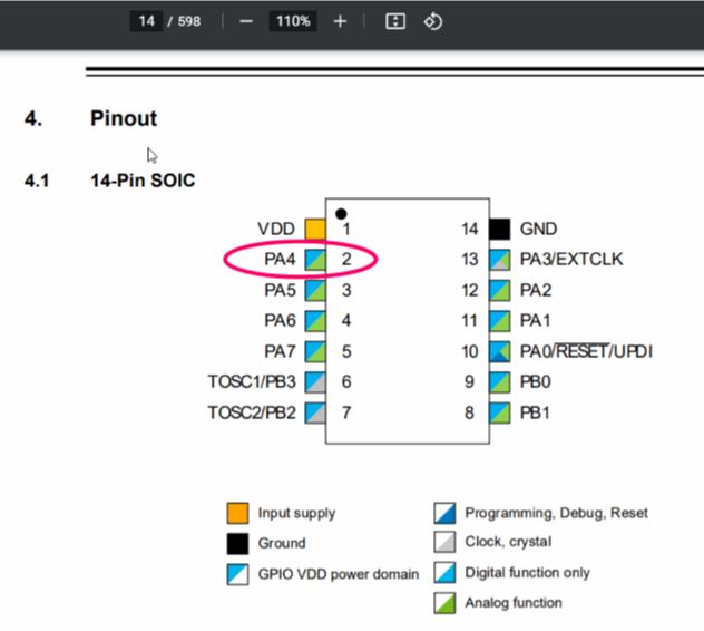
I have taken the most important information for everyday work during the fabacadmy time from the pin assignment plan. Most of the information I need to program the microcontroller can be found here. Below I have shown the pin assignment plan from the data sheets of the two used.
Here we come to an important difference between the ATtiny 1614 and ATtiny44 boards. I can program the attiny1614 via the updi interface and (i.e. Arduino pin 11) the ATtiny 44 via ISP. I need considerably more connections via ISP (in-circuit serial programming). In addition to VCC and GND, I also need MISO, SCK, RST and MOSI.
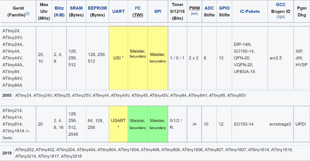
Further differences can be found in the table under the following link.
In addition, to program the arduino, I needed the names of the pins with which the Arduino programming environment works. For this reason, I have made use of the illustrations on which this information can also be easily taken.
Here you can see very nicely how you can go to the right and to the left in addition to the numbering of the pins and receive information for the arduino programming environment and for the function assignments.
It can now be read that if I want to assign pin 2, I have to select 0 in the arduino programming environment. In addition, it becomes readable that PWM is possible on pin 2. Of course, pin 10, the updi input through which the board is programmed, is also particularly important for this assignment.
datasheets
pwm/fading/arduino
Here I take Jeff’s code and adapt it to my needs.
First of all, I determine the two pins on which something should happen. In this case the button on 9 and the led on 0. Next I tell the microchip that when the button is pressed, pin 9 to 1 is activated. In the void setup I specify that the led is the output and the pin is the input.
The pin mode of INPUT_PULLUP means that the pin is to be used as an input, but that if nothing else is connected to the input it should be ‘pulled up’ to HIGH. In other words, the default value for the input is HIGH, unless it is pulled LOW by the action of pressing the button.
The status of the button is now repeatedly queried in the loop. When the button is pressed, the value i rises in each run of the loop by 5 at a time and sends the value (PWM wave) to the led with analogwirte. An analog value between 0 and 255 is output to the led. The led will shine brightest at 255. The calculation of the output takes place in the for loop
The duration of the for loop has a delay of 50 ms. With each new start of the loop, a new value is output for the specified time that the process should take.
const int button = 9; // Set number of the button pin
const int led = 0;   // Set number of the LED pin

byte buttonState = 1; // Variable for button status

void setup() {
  pinMode(led, OUTPUT);   // Set LED as an output
  pinMode(button, INPUT_PULLUP); // Set button as an input with PullUp resistors configuration
}

void loop() {
  buttonState = digitalRead(button); // Read state of the button value

  if (buttonState == LOW) // Check if button is pressed
  { // If button is pressed, Turn on LED
    delay(500);

    // fade in from min to max in an increments of 5
    for (int i=0; i<=255; i+=5){
    analogWrite(led, i);
    delay(50);}

    // fade out from max to min in a decrement of 5
    for (int i=255; i>=0; i-=5){
    analogWrite(led, i);
    delay(50);}

  } else {
    digitalWrite(led, LOW);} // If button is not pressed, keep the LED off
}
pwm in c
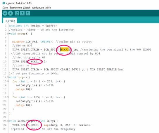
With Harley Lara’s help, I wrote a code for pwm in c.
First i set the maximum period with - unsigned int Period = 0xFFFF;
I define pin 4 as an output.
TCA0 is the timer counter.
HCMP1 - sets the period. Here you can set the time in which pwm is 0 or 1.
I can split the timer to my needs to get the pulse i want.
The dutycycle gives the pwm the value and indicates the length the pwm is set to 1.
In the loop the dutycycle increases and decreases as it is calculated in the formula of the for loop.
The value is counted over 10ms and increased or decreased when the loop starts again.
After each new “void loop” the value is output to the led and lets the led light which lays on pin 4 become brighter or darker.
unsigned int Period = 0xFFFF;
//period - timer - to set the frequency
void setup() {

  pinMode(PIN_PA4, OUTPUT); //define pin PA4 as output
  TCA0.SPLIT.CTRLB = TCA_SPLIT_HCMP1EN_bm; //split the timer - high byte compare 1 enable
//TCA0 timer.SPLIT cut in pieces.CTRLB control by WO4
  TCA0.SPLIT.HCMP1 = 0; // Set duty cycle 0%
  TCA0.SPLIT.CTRLA = TCA_SPLIT_CLKSEL_DIV16_gc | TCA_SPLIT_ENABLE_bm; // set clock devider to 16
}

void loop() {
  for (int i = 0; i <= 255; i++) {
    setDutyCycle(i); //~25%
    delay(10);
  }
  for (int i = 255; i >= 0; i--) {
    setDutyCycle(i); //~25%
    delay(10);
  }
}

void setDutyCycle(byte duty) {
  TCA0.SPLIT.HCMP1 = map(duty, 0, 255, 0, Period); //period - timer - to set the frequency
}
First I looked at the pinout to find the led.
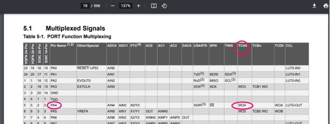
After that I looked at the timer counter for the led pin, thats w04.

Than looking into the arduino mega tiny core to implement the tca.

I oriented at the tutorial how to use the tca in this at tiny microcontroller.
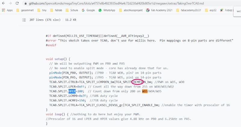
Here you find some reference to setup the split mode.
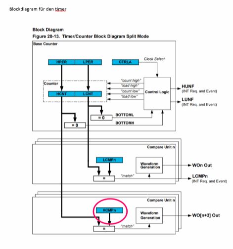
Blockdiagram for the timer.
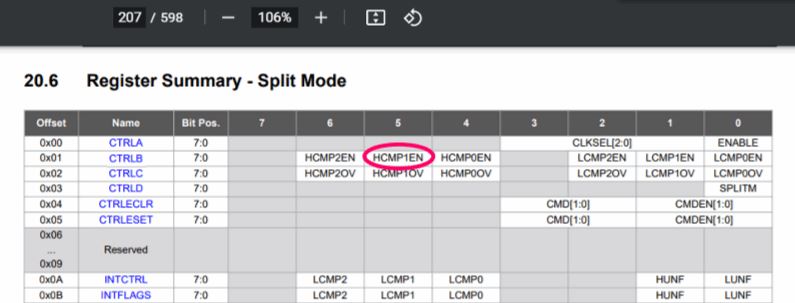
In the dataseet is this table for set the register for my split mode.
Set up the split mode
clock speed
If I want to change the clock speed, I first have to decide if I use an internal or external clock. Datasheet page 81.
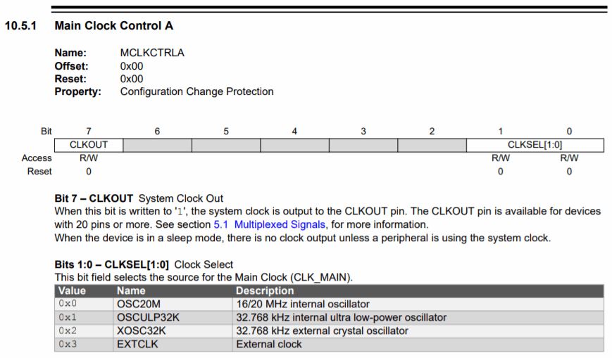
If I wanted to use a external clock I have to set pin 0:1 to e.g. 0x3.
Since I am using a internal clock, I set it to 0x0.
For setting the prescaler I would refer to page 82 and set the register MCLKCTRLB.
PWM
The pwm options can be found starting at page 176.
ADC
ADC can be found on site 427.
DAC - Digital-to-Analog Converter
In contrary to the ATtiny 44 the 1614 also has an DAC. The information can be found starting from page 455.
group assignment
files
board_1_with_ATtiny1614-SSFR.kicad_pcb
board_1_with_ATtiny1614-SSFR.sch
bord_2_with_a_ATtiny44-SSU.brd
bord_2_with_a_ATtiny44-SSU.sch