5. Electronics production
- Characterize the design rules for your PCB production process: document feeds, speeds, plunge rate, depth of cut (traces and outline) and tooling. Document your work (in a group or individually):
Group assignment page: here.
My individual part:
I have documented it in the Test pieces section.
- The end mills I used were: for traces, a V-bit 0.2-0.5mm and a cylindrical 0.4mm; for holes and cutting, a cylindrical 0.8mm.
- The milling machine I used was the Roland MDX-40 with its VPanel.
- PCB board material = FR2.
- Make an in-circuit programmer by milling and stuffing the PCB, test it, then optionally try other PCB fabrication process:
For this assignment I have manufactured a Hello board, an USB-FTDI board and a FTDI-UPDI adapter.
Before making the circuit boards we have made testing boards with the tools we were going to use, so we can configure the traces and clearance with a physical reference.
I have put the circuit boards first and then a general explanation of the steps I follow to mill a PCB.
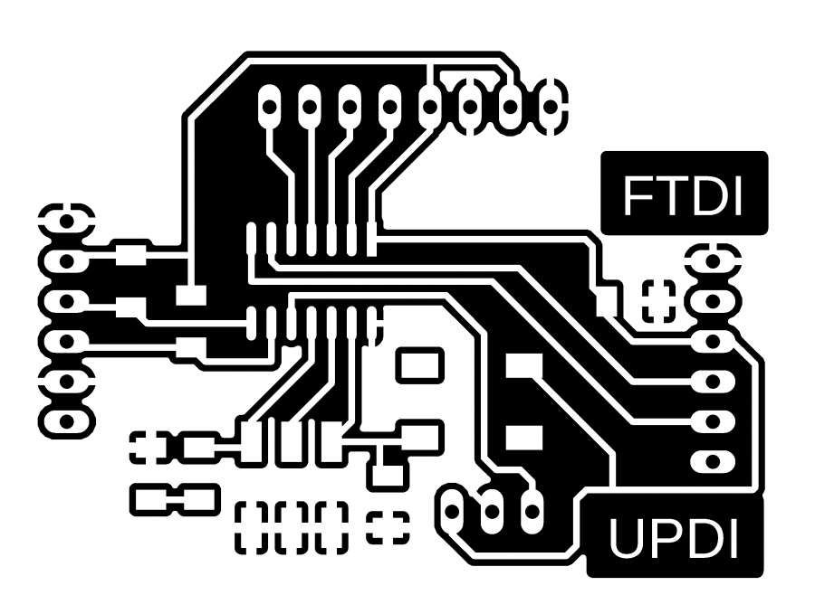
HelloD1614
Based on the ATtiny1614 and inspired from the Adrianino, the HelloD1614 is a simple board that can be used to test the features of the new ATtiny microcontrollers. The board exposes the full pinout of the ATtiny1614, and offers UPDI as one of the way of programming the chip.
End mills:
Traces: cylindrical 0.4mm
Cut: cylindrical 0.8mm
-
Images:
-
Traces:
-
Holes:

-
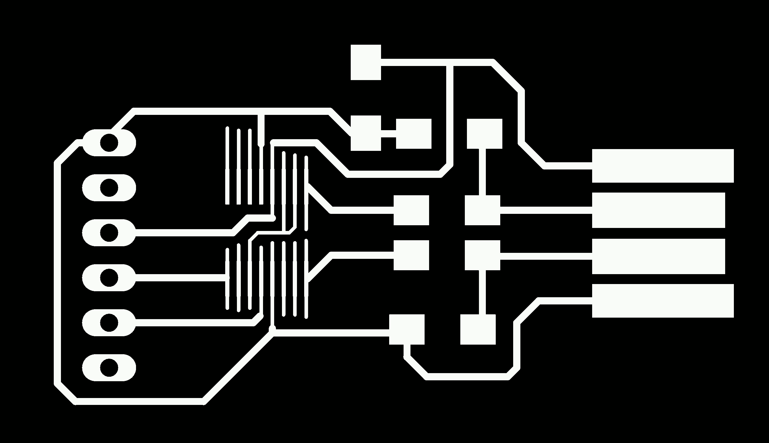
Outline:

-
-
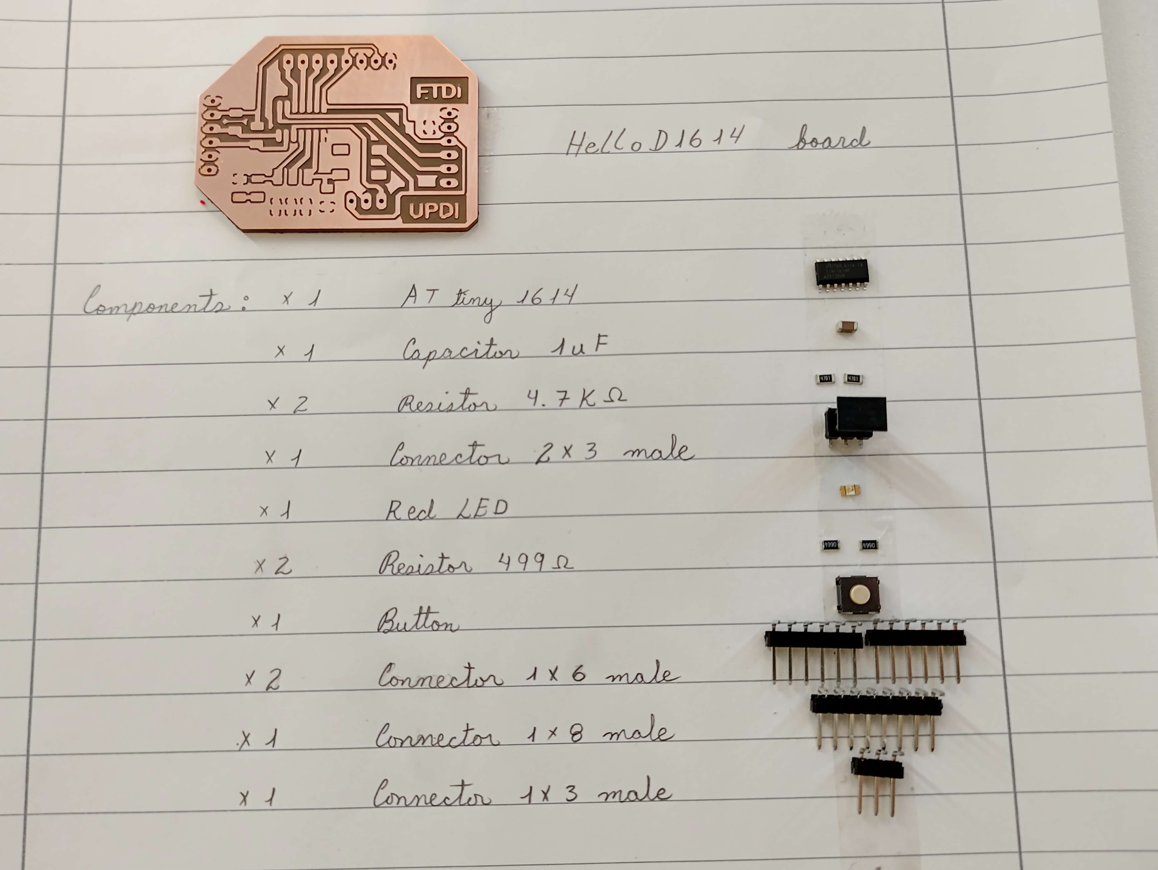
Before soldering:
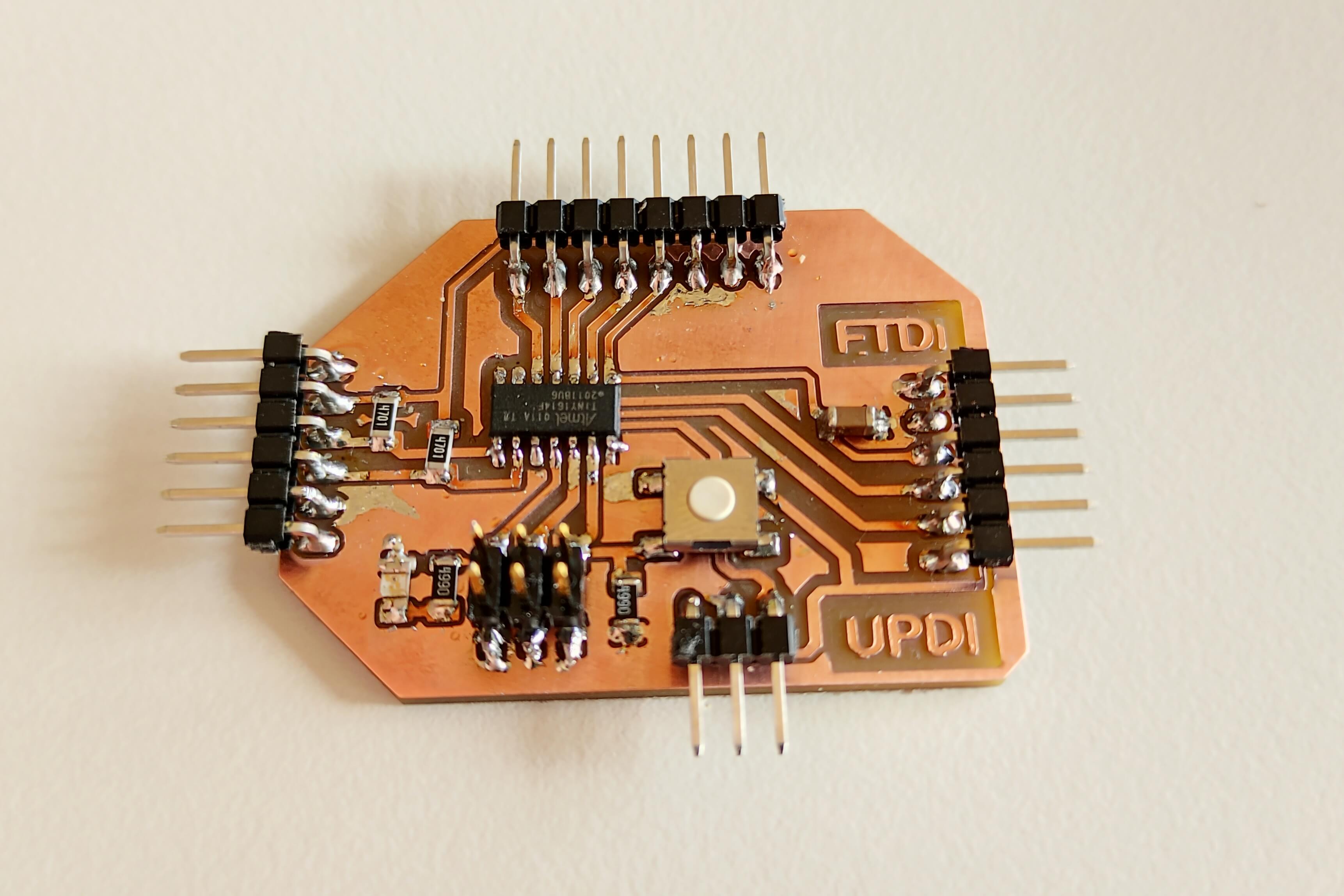
Resulting board:
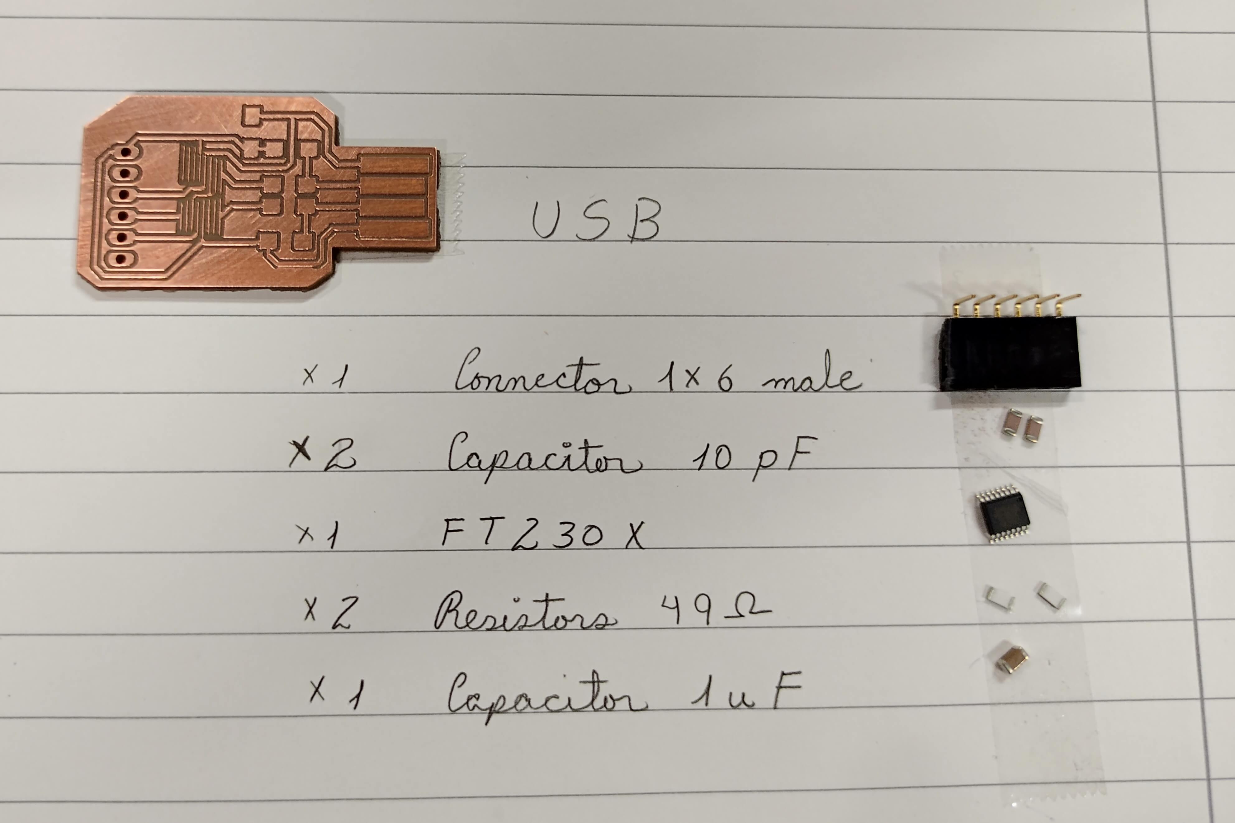
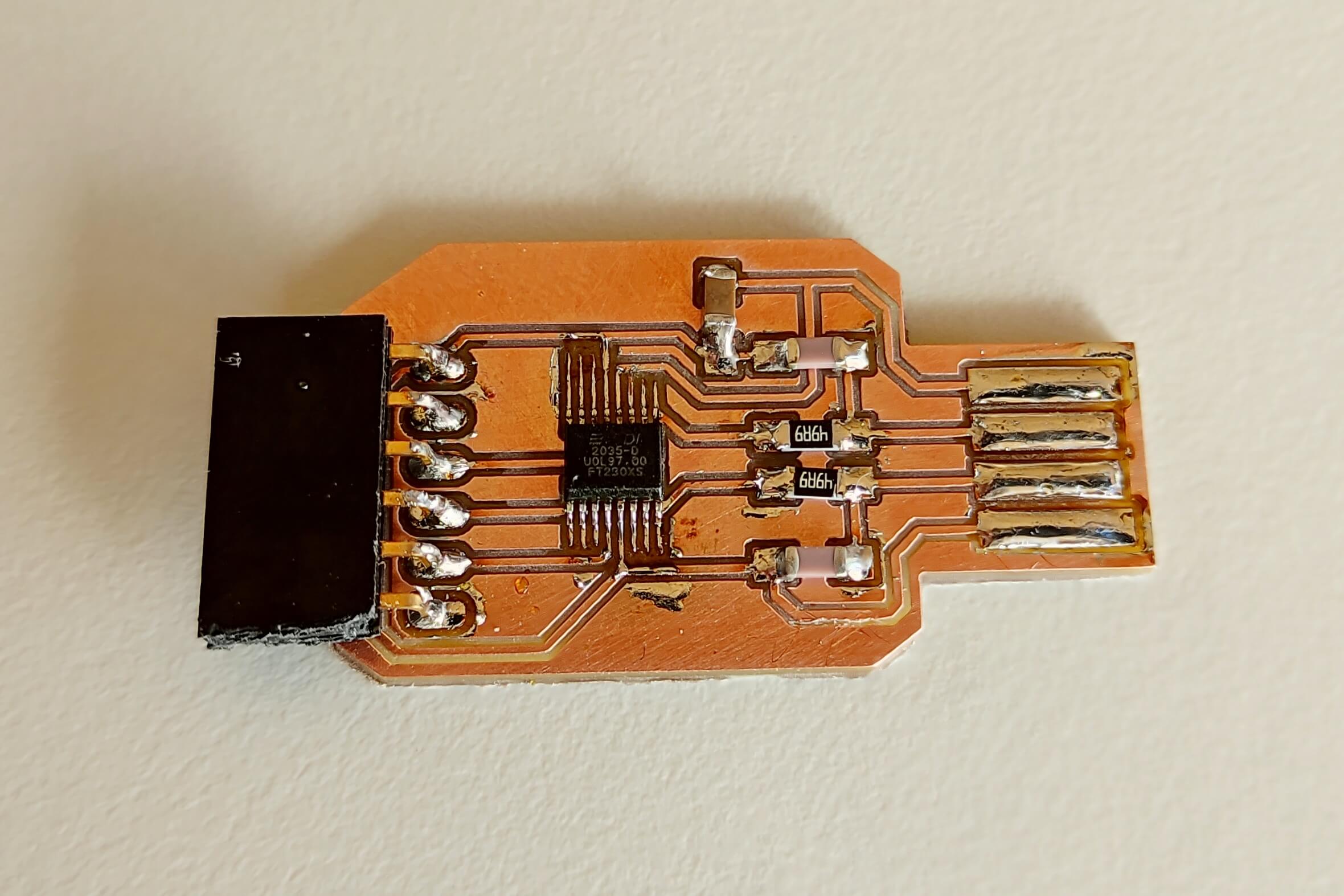
FTDI-USB
The FTDI-USB is a board that implements similar functionalities of an FTDI cable. Hosting the FT230X, the board can basically convert from USB to serial and can be used for the communication with your board, your sensors etc. It is also compatible with UPDI programming.
End mill for traces and cut: V-bit 0.2-0.5mm
-
Images:
-
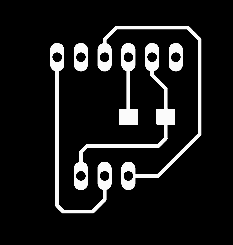
Traces:
-
Holes:

-
Outline:

-
-
Before soldering:
Resulting board:
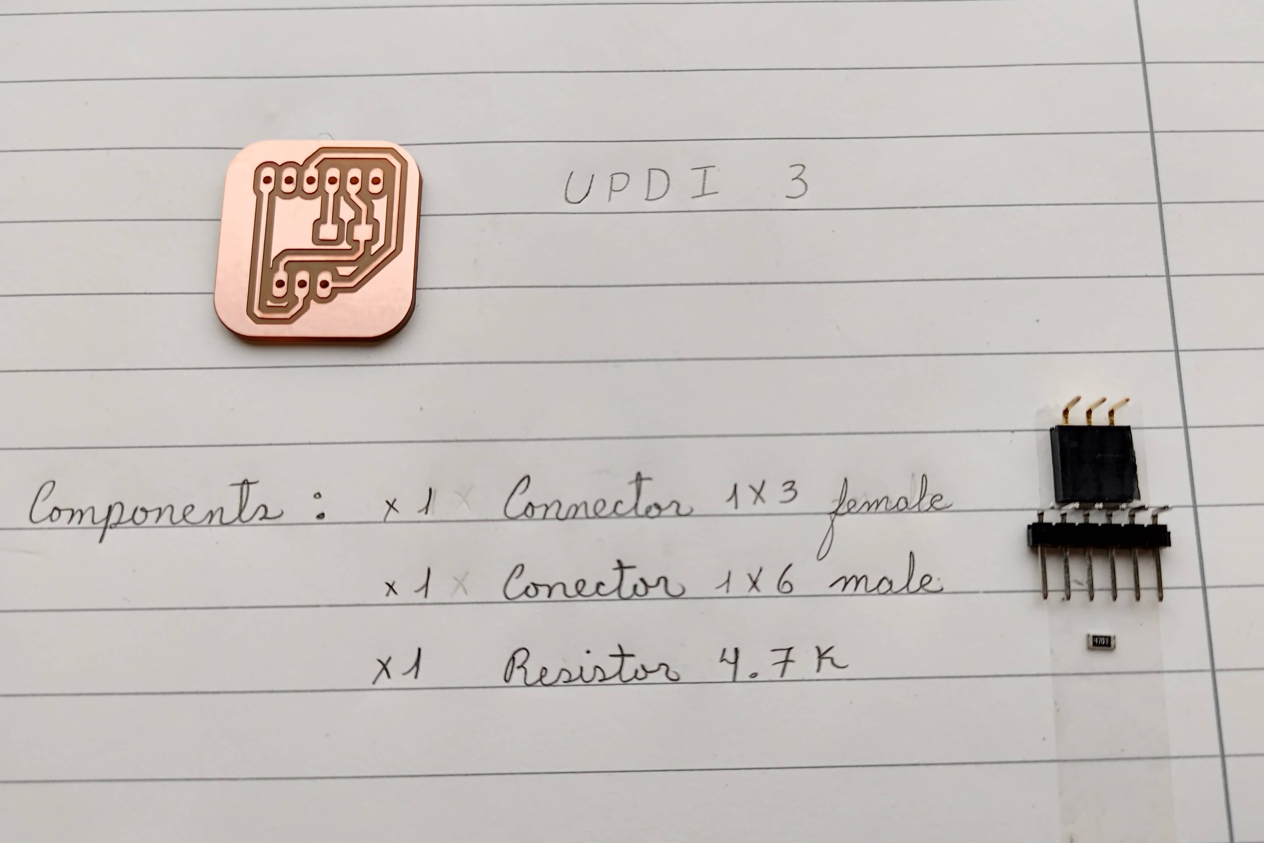
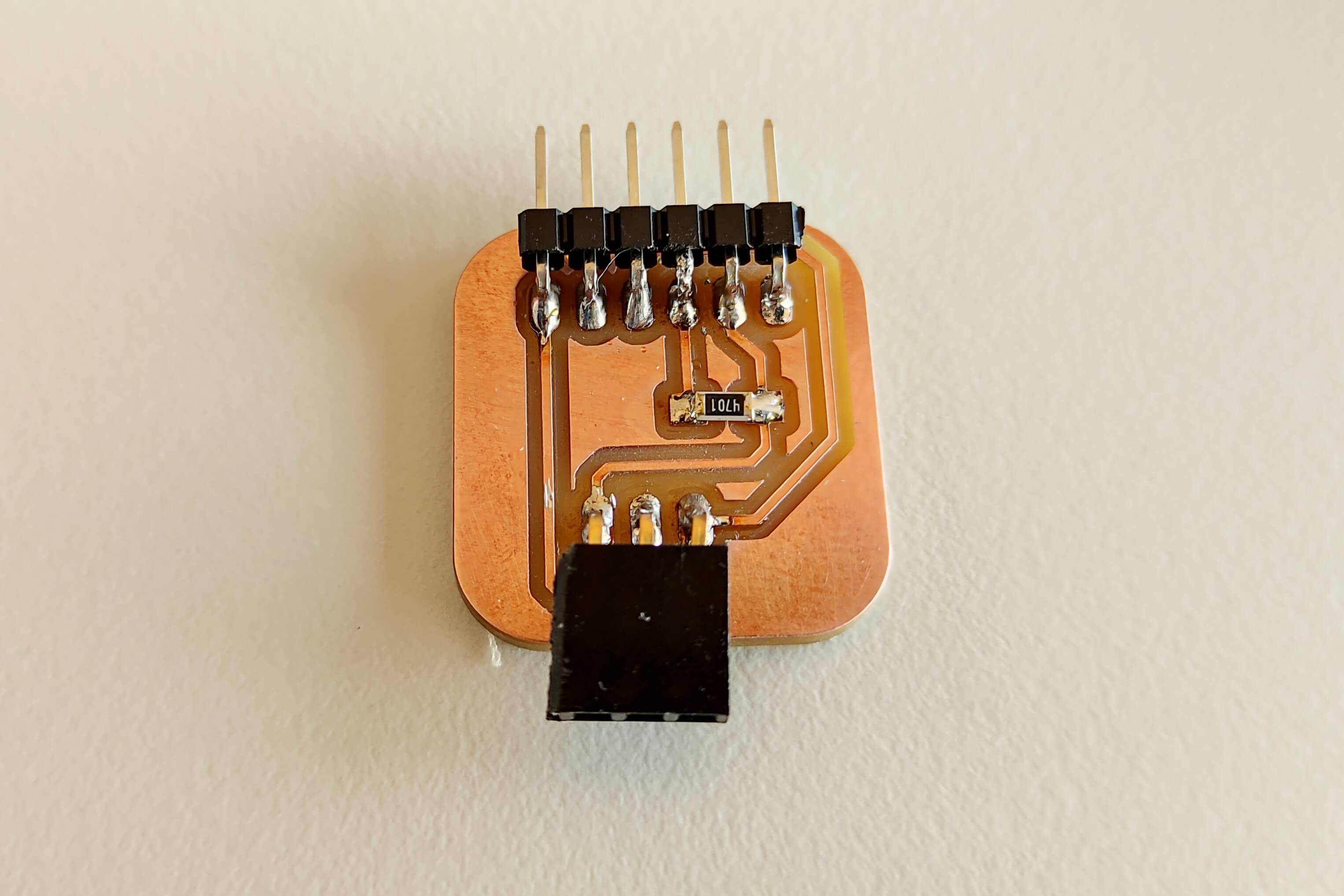
UPDI3
The UPDI-3, is a simple add-on board allowing the programming of the new AVR microcontroller from Microchip. The board works as bridge between the UPID target, and a serial communication. The serial communication can from different sources, eg. an FTDI cable or the FTDI-USB.
End mills:
Traces: cylindrical 0.4mm
Cut: cylindrical 0.8mm
-
Images:
-
Traces:
-
Holes:

-
Outline:

-
-
Before soldering:
Resulting board:
Testing boards
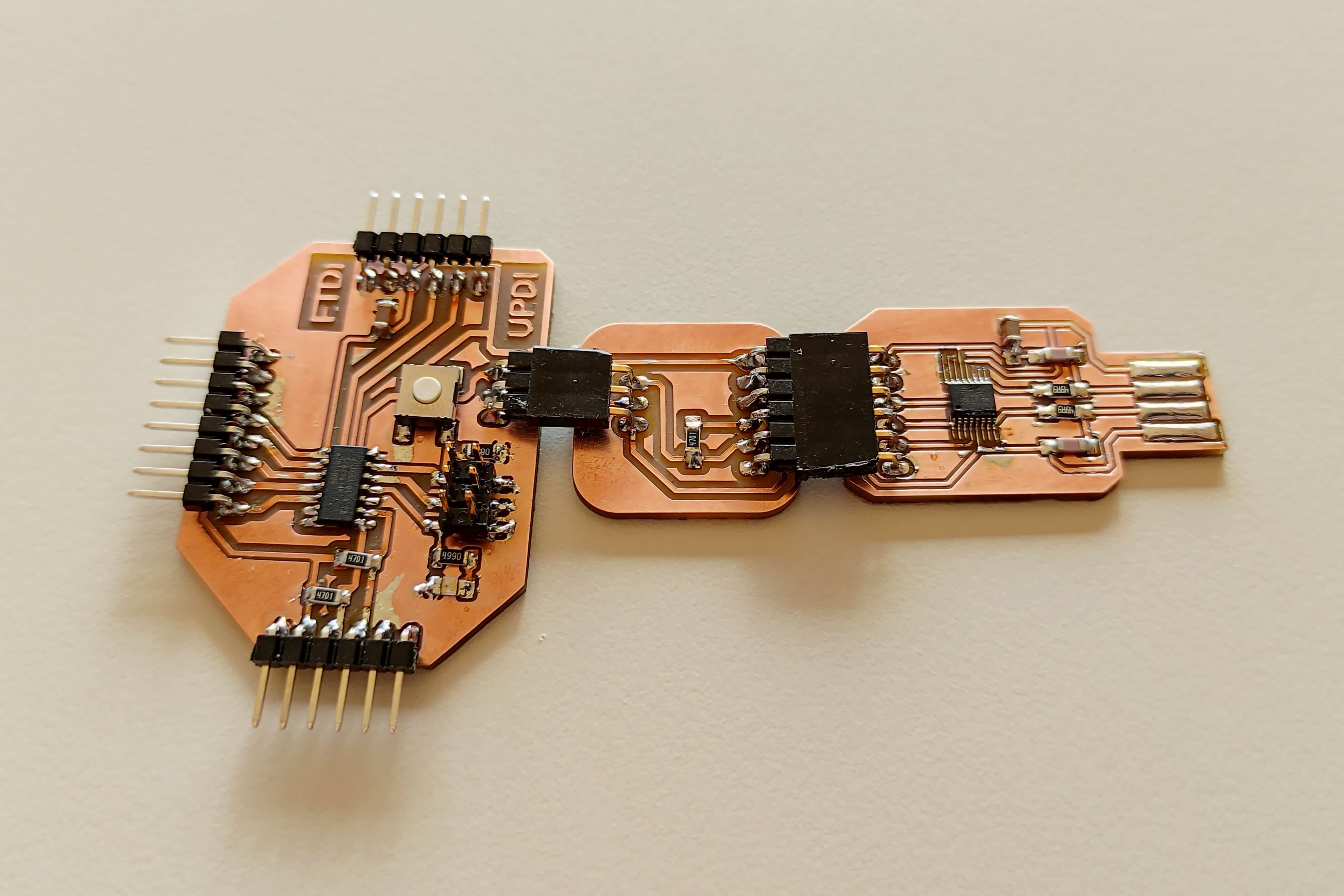
Connection
This is how the boards connect together:
First settings
For the first time we need to add the MegaTinyCore to the Arduino IDE:
- Open the Arduino IDE.
- File > Preferences
- Paste the following link in Additional Boards Manager URLs: http://drazzy.com/package_drazzy.com_index.json
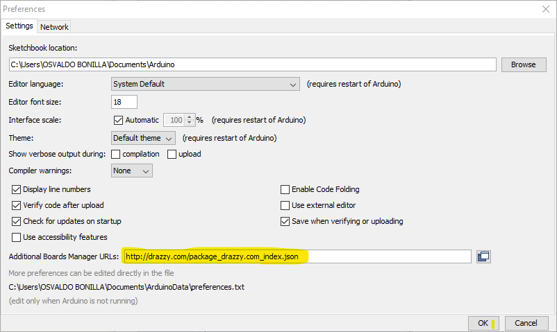
- Press OK
- Tools > Board > Boards Manager
- Search for MegaTinyCore (by Spence Konde):
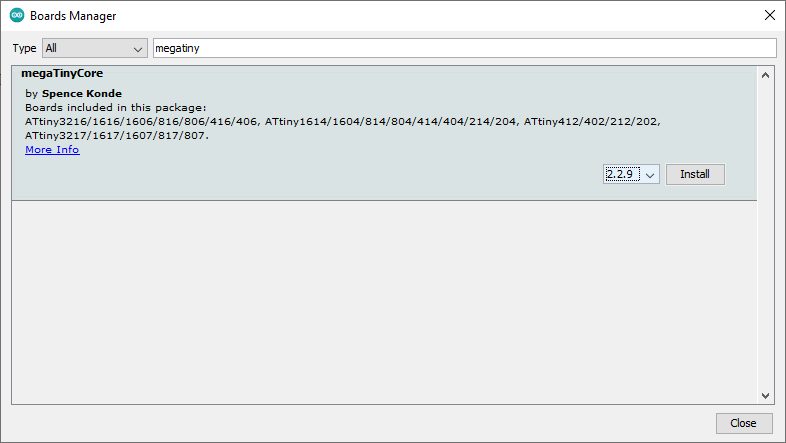
The latest version when I made it was the 2.2.9, which I had some issues with (very long installation time and then no compiling); version 2.2.8 presented no problems at all. Take in account that the only test I made was the Blinking with the onboard LED.
Code
Blinking LED:
1 2 3 4 5 6 7 8 9 10 11 12 13 14 15 16 17 18 19 20 21 22 | |
Upload a Code
-
To upload a code to the Board, we just need to use the following highlighted settings in the Arduino IDE:
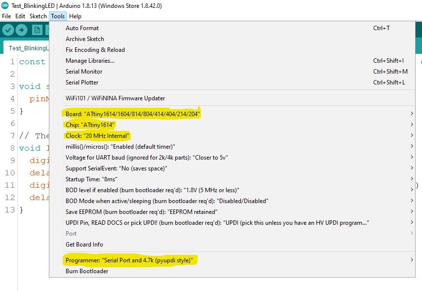
-
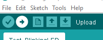
After selecting these options and when testing the board by the first time, press Burn Bootloader to setup the Microcontroller; then you can just press the Upload button:
Performance
It’s recommended to use an extension cable or an USB hub for connecting to the PC.
Video1: BlinkingLED test
Making process
It’s worth mentioning that there are three processes we do for a PCB:
- Traces
- Holes
- Outline
G-code generation
For it we used the FabModules - an only tool.
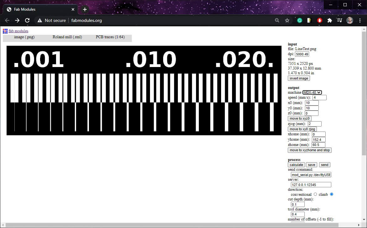
- input format > Select image.png > Select the image from the PC.
- output format > _Roland mill (.rml)
Output format is going to depend on the milling machine you have.
- process > Select process to configure.
For traces: PCB traces. For holes and outline: PCB outline.
- In output tab select machine to use.
- Fill in the text boxes.
- Press calculate.
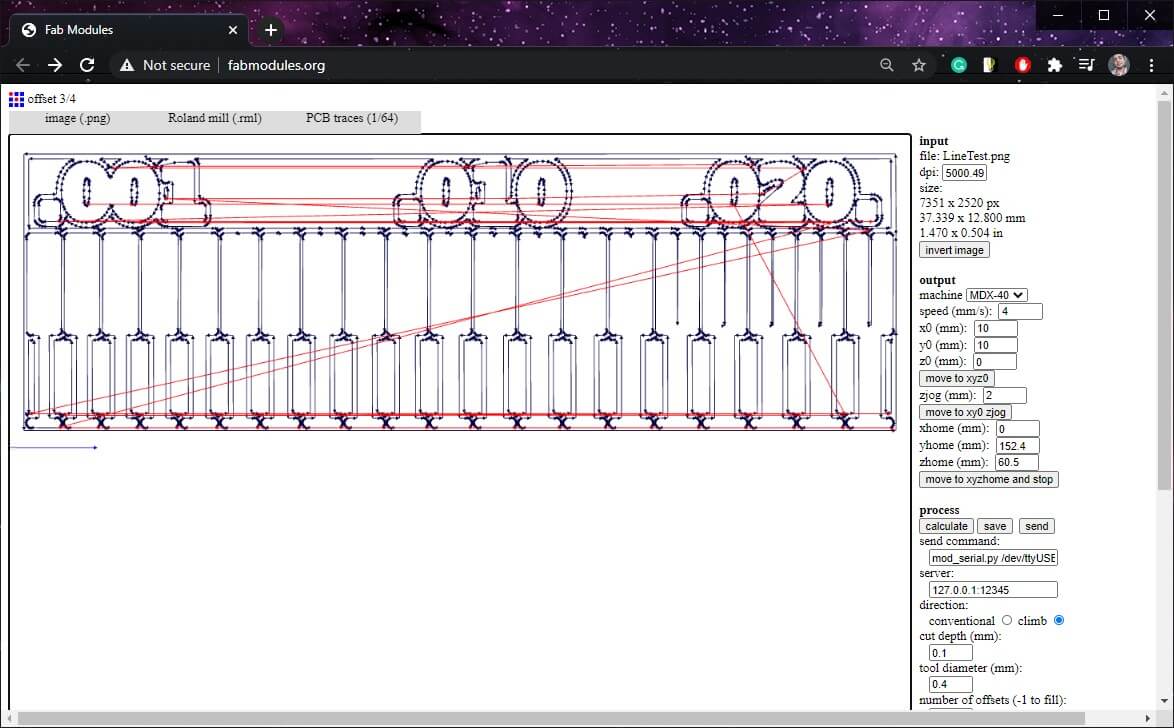
- After that, press save.
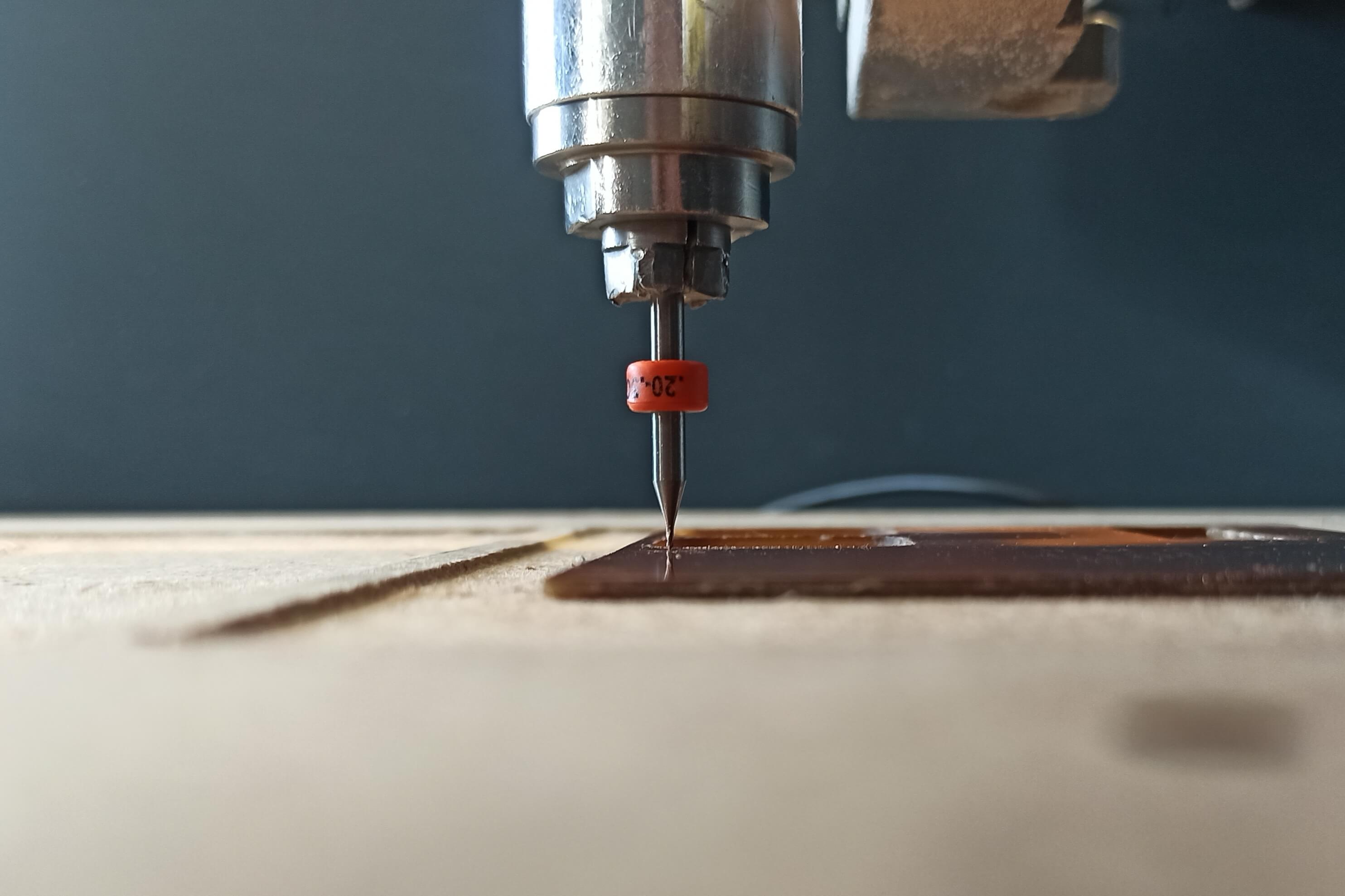
Mill process
Preparation
- Put the copper board on the of the machine.
- Put on the machine the appropriate Collect for the bit we are going to use (bit shafts come in different diameters).
- Put the bit on the collect and adjust it.
- Using the VPanel software, adjust the Home point.
XY will be the bottom-left corner of the board, Z axis will be when the bit slightly touches the board.
Ways to find the Z-0
-
Using Continuity of the multimeter, putting one tip on the bit and the other one on the board.
-
Using your hearing power:
- Start bit rotation.
- Slowly lower the tool until you hear a different sound (a soft milling).
-
Using your vision power:
- Start bit rotation.
- Slowly lower the tool until you an small amount of chip (a soft milling).
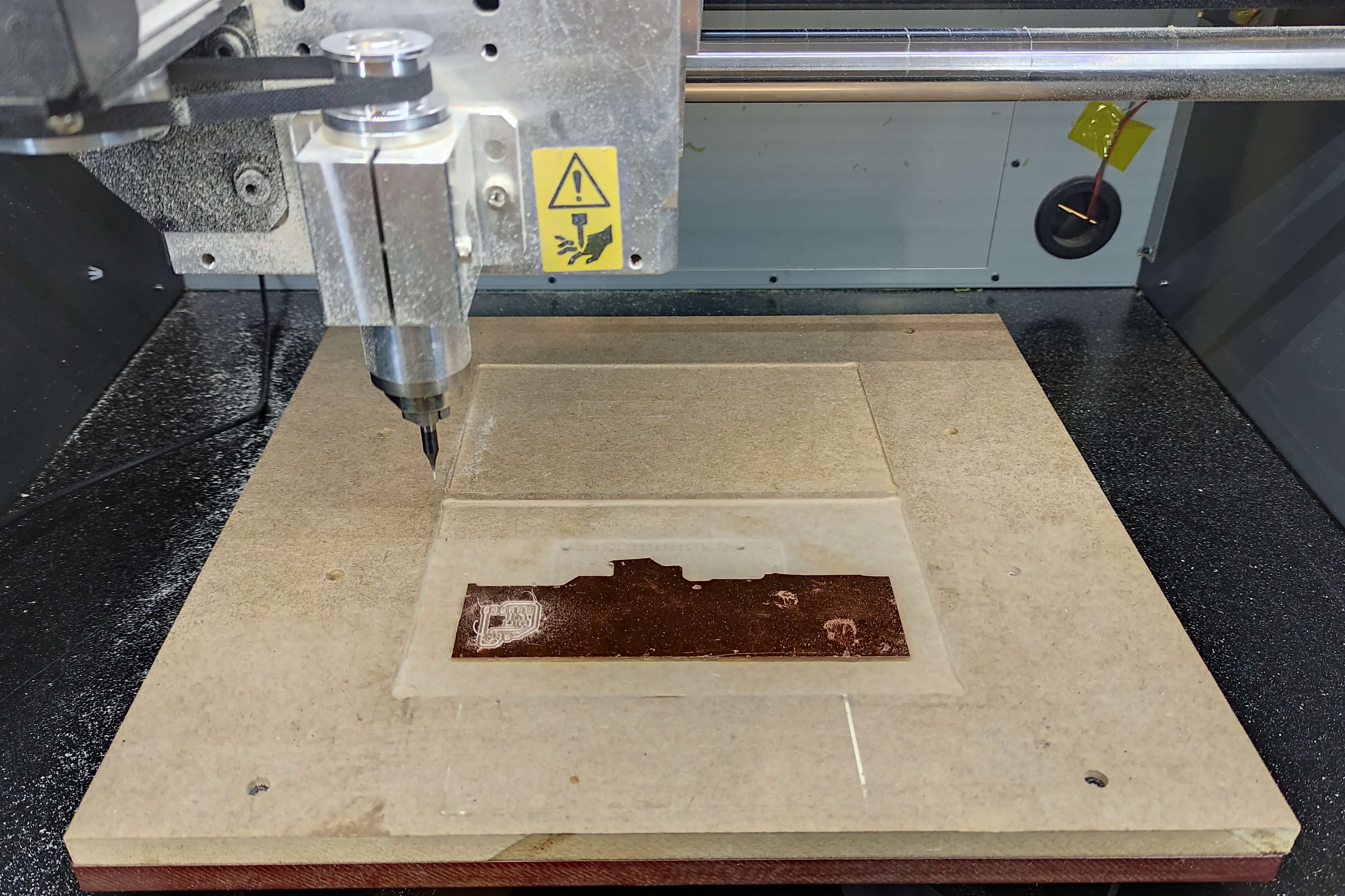
Milling machine
- Import the the Code in the VPanel.
- Press Output to start milling.
PCB done:
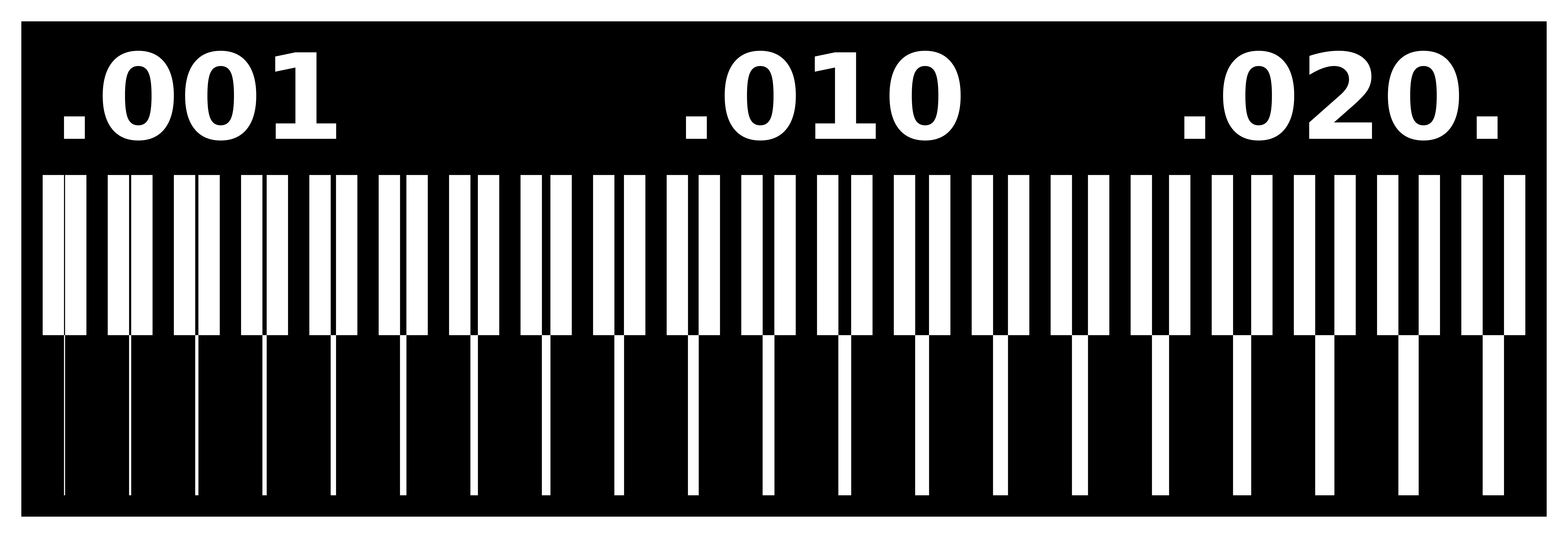
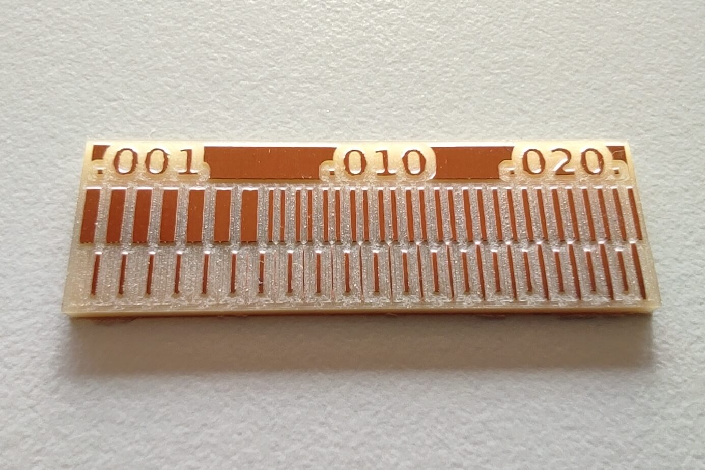
Test pieces
As usual it’s necessary to make a test beforehand; in this case with the end mills you’ll be using, a simple like the follow one let you know the trace thickness you can do, you can also determine the optimum cutting speed and spindle:
Images:
-
Traces:
-
Outline:

Test piece 1
End mills:
Traces: cylindrical 0.4mm
- Cutting speed: 2mm/s
- Spindle speed: 15,000RPM
- Cutting depth: 0.1mm
Cut: cylindrical 0.8mm
- Cutting speed: 4mm/s
- Spindle speed: 8000RPM
- Cutting depth: 0.6mm
Result:

Conclusions:
- Thinnest trace = 0.06mm
- Minimum clearance = 0.16mm
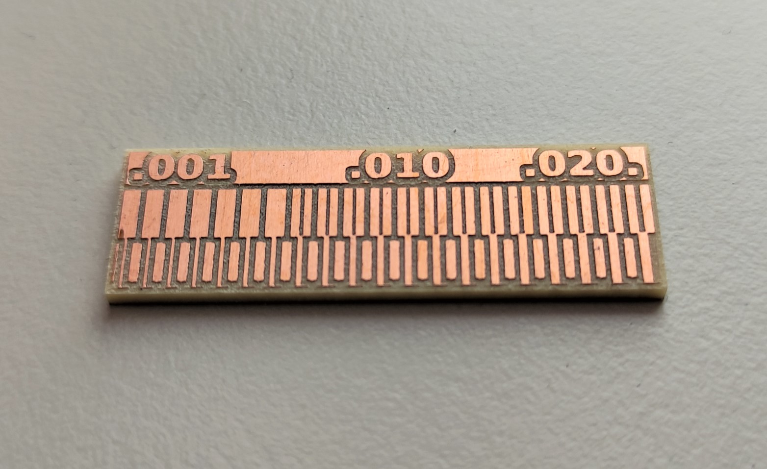
Test piece 2
I made a test with my colleague Harley Lara using a V-bit 90° 0.2-0.5mm in high speeds to increase production rate.
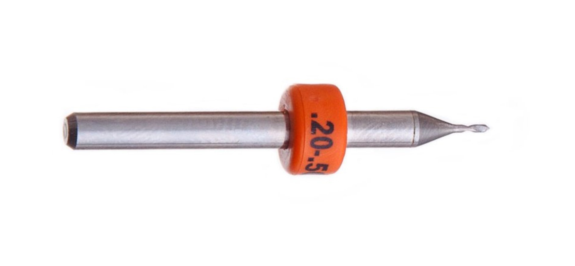
Image taken from cirQoid
Video of the process:
Traces:
- Cutting speed: 20mm/s
- Spindle speed: 15,000RPM
- Cutting depth: 0.1mm
Cut:
- Cutting speed: 20mm/s
- Spindle speed: 8,000RPM
- Cutting depth: 0.2mm
Result:
Conclusions:
Under the settings used, for a functional board:
- Thinnest trace = 0.13mm
- Minimum clearance = 0.08mm
Test piece 3
I made a second test using the 90° V-bit 0.2-0.5mm, but in a monoFab SRM-20 milling machine, the objective was to test a different depth (the Spindle speed had to change due to different machine capabilities, then I also reduced the Cutting speed proportionally).
Video of the process:
Traces:
- Cutting speed: 12mm/s
- Spindle speed: 9,000RPM
- Cutting depth: 0.08mm
Cut:
- Cutting speed: 12mm/s
- Spindle speed: 9,000RPM
- Cutting depth: 0.2mm
Result:
Conclusions:
Under the settings used:
- Thinnest trace = 0.01mm
- Minimum clearance = 0.08mm
Observation:
When using a V-bit… the deeper you mill, the thicker the milling will be; then it’s a bit tricky to calculate the tool depth precisely when generating the g-code (of course we can use some basic mathematics for it, but we are also talking about a tenth of a millimeter when taking Z-0 could make a difference). It’s different when we use a cylindrical tool.
Soldering
I have solder only basic things like jumper cables before, then it was also a good learning for me.
In addition to the lecture given by my instructors, I have checked some YouTube tutorials, to start this one resulted very useful: How to Solder on PCB properly | Soldering Techniques for Beginners.
The process that I followed was:
- Prepare all of the components to be soldered properly tagged with the board:
- Check the tip of my soldering pen and soldering wire.
- Determine the temperature with which I feel most comfortable (365°C in my case); it’s affected by the tip used, the experience on soldering and the soldering wire.
- Check the datasheets and pinouts for each components to make sure I solder them in the right position (or it could result in damaged components and a useless board).
- Start soldering 😄.
- At the end it’s recommended to check the connections with a multimeter in the continuity mode to make sure that everything is properly connected and we have no short circuits.
Considerations and recommendations:
- Make sure that the suction system is working, otherwise wear a proper mask for this task.
- A shiny finish makes sure that your connections are going to last a long time.
- The longer the time you keep the tip on the board… the more you risk the components to be damage by heat and the more and faster the flux evaporates; then the temperature used should offer you a quick exposition time to the heat.
- Adding flux to the soldering makes the heat transfer easier… that means a shorter heat exposition time, a nicer finish and better connections between the components.
Files
- TestPiece.rar
- FTDI-USB.rar
- UPDI3.rar
- HelloD1614.rar