4. Computer controlled cutting
- Characterize your lasercutter’s focus, power, speed, rate, kerf, and joint clearance. Document your work (individually or in group):
Group assignment page: here.
My individual part:
- The laser cutter’s focus is in the Determining focal length section.
- And I have added a section explaining how to measure the Kerf.
- The power, speed and frequency are described for each material and process as “Parameters used” below the image of each practice, and are taken from the machine manual.
- Design, lasercut, and document a parametric press-fit construction kit, which can be assembled in multiple ways. Account for the lasercutter kerf:
I have made a Key-chain with 3mm transparent acrylic and the construction kit with 3mm cardboard (the recommendation for this assignment).
- For designing I used Fusion 360.
- For setting up the cutting I used RhinoCeros.
- The laser cutter I used was the Epilog Zing 24 - 30 Watts.
- Cut something on the vinylcutter:
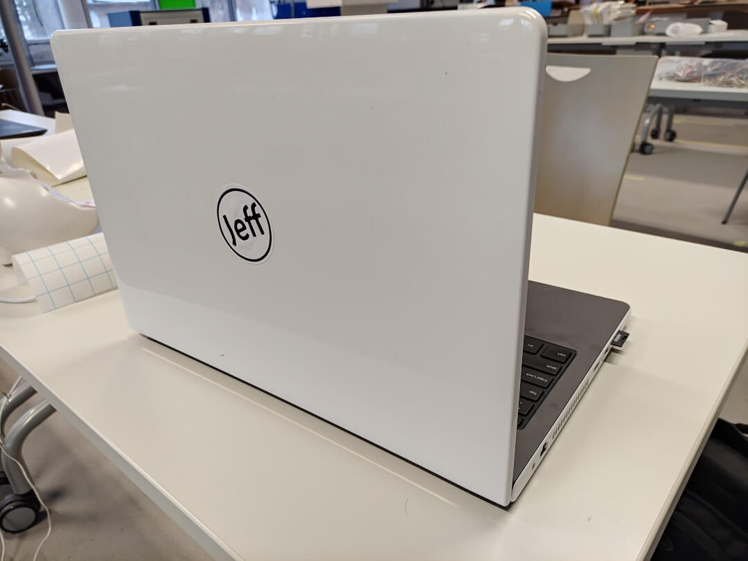
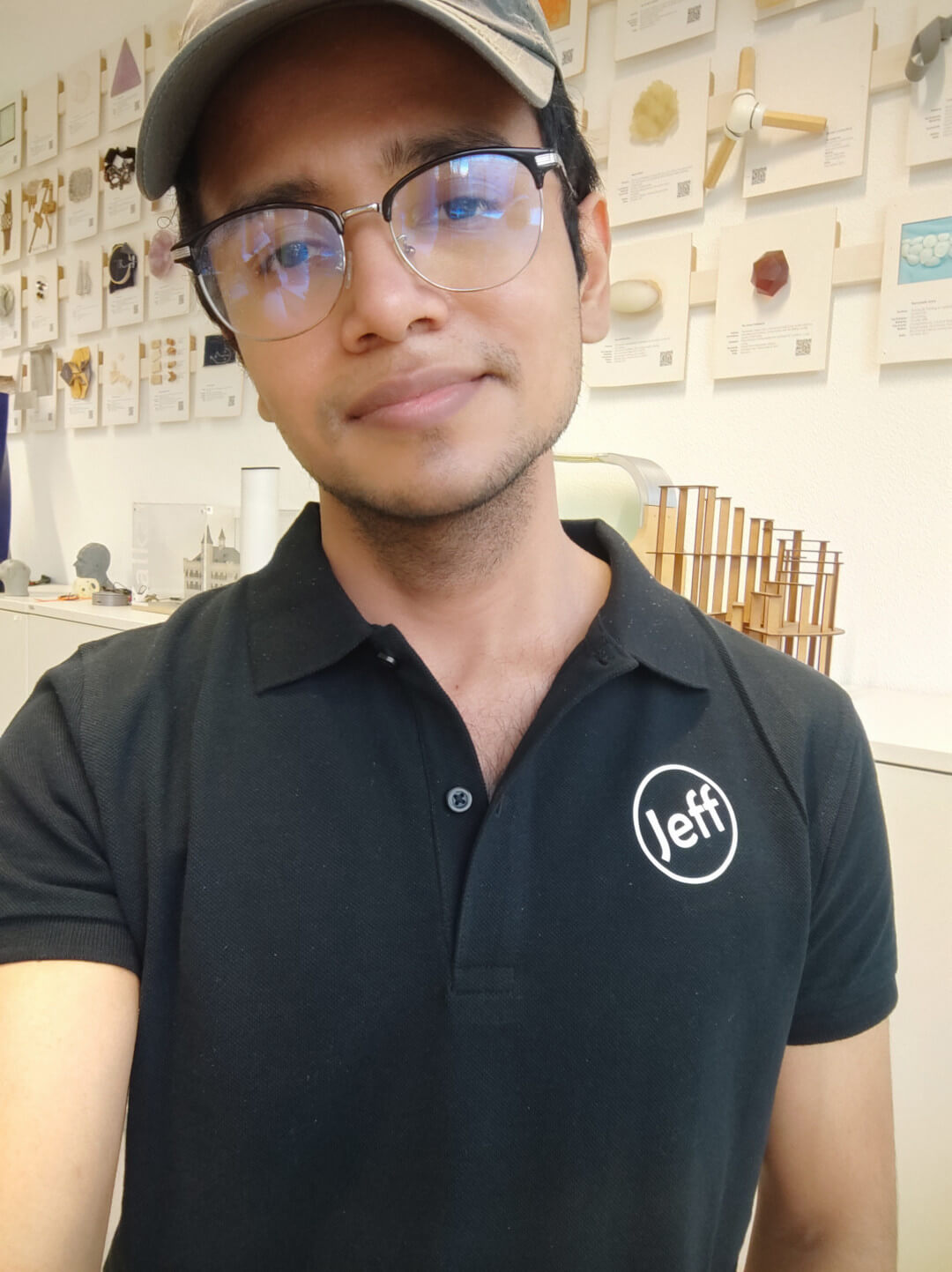
I have made an sticker for my laptop and a T-shirt.
- For designing I used Fusion 360.
- For setting up the cutting I used Silhoutte Studio.
- The vinyl cutter I used was the Silhouette portrait 2.
- For Heat transfer print I used a Heat press.
Parametric design
For this part I made the pieces for my press-fit construction kit.
It consists of pieces that you can assembly on different ways to quickly prototype basic bodies.
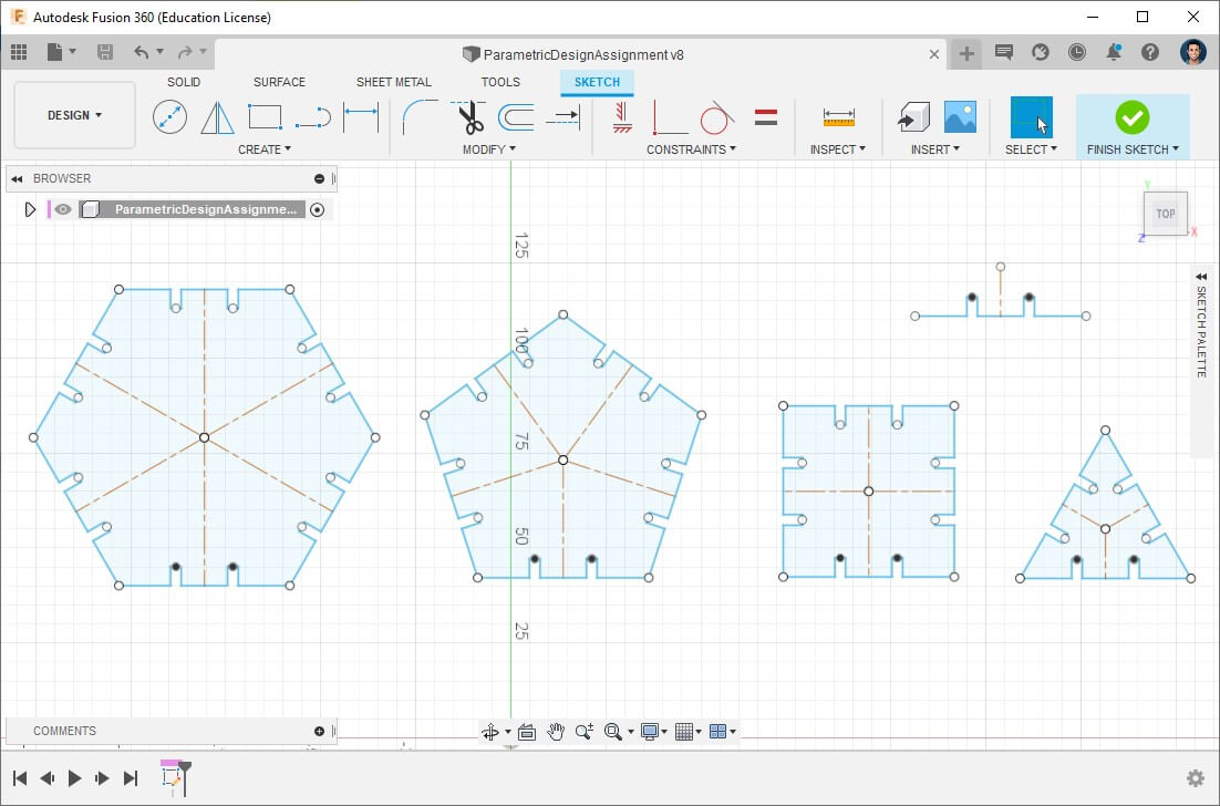
Parametric design consists of listing a sheet with all the important parameters for our design such as length, width, thickness, patterns, diameters and more either for simple values or more complex functions; then we can use directly the functions instead of type numbers; it allows us to keep the key parameters in our design and change them without the need of changing the objects by ourselves, very useful when it comes to use materials with different thickness, kerf and so on.
Chronologically, it depends on the mind of the designer, you can either make a “normal” sketch/body and then make it parametric or star with defining the parameters and then based on them, create the project.
I rather creating parameters first and then sketch.
Create parameters
- Open Parameters window: In the Design workspace > Modify > Change parameters.
- Add User Parameter.
- Enter our costumed values, in this case I used
MaterialThickness,KerfandScale(which I used to resize the figures). - OK.
Apply parameters
- Create a Sketch as usual: In the Design workspace > Create sketch > Select XY plane.
- Start drawing, but when write the dimensions, use the corresponding created parameters where needed:
- If it’s a scale parameter: multiply it by the desired original size.
- If it’s a specific number: just introduce it.
Laser cut
Key chain
Well, in the end I used it as an accessory in my backpack… 🤷🏽♂️
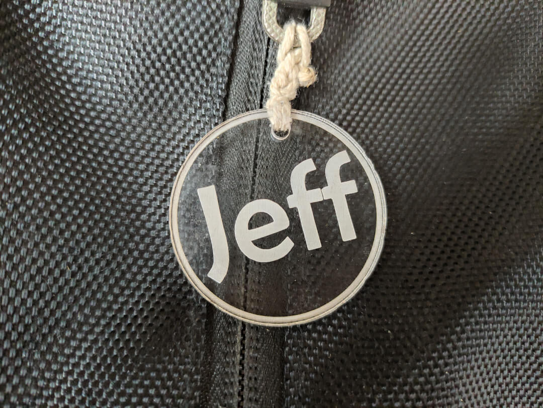
Material: 3mm acrylic
Parameters used:
Cut (vector):
- Speed: 15%
- Power: 100%
- Frequency: 100Hz
Engrave (raster):
- Speed: 100%
- Power: 15%
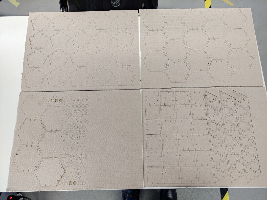
Construction kit
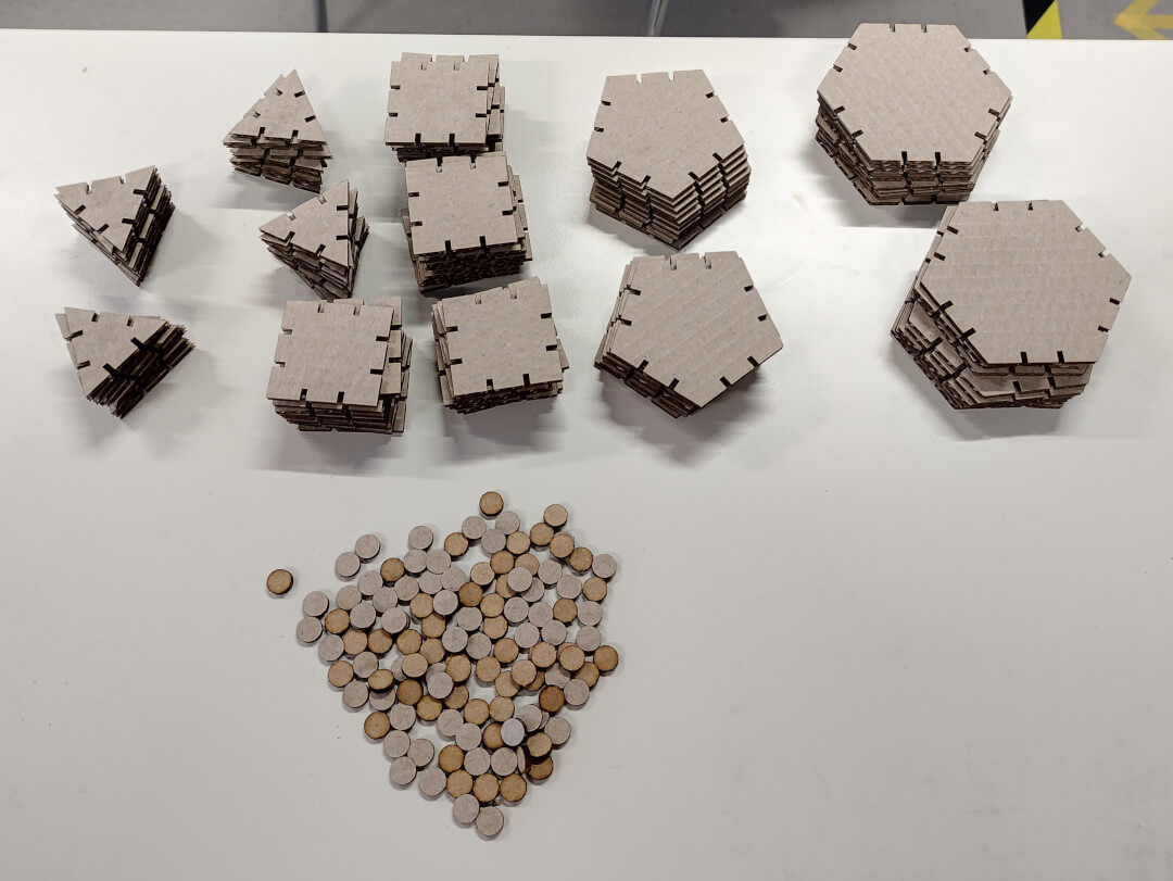
Random body shapes with the pieces:
Material: 3mm cardboard
Parameters used:
Cut (vector):
- Speed: 100%
- Power: 60%
- Frequency: 40Hz
Process
Determining focal length
Usually the lenses come with its focus tool, but it’s also an interesting exercise to know how to determine it and see what happen when it’s not in focus.
When it comes to laser cutters, “focus” is the thinnest point of the laser which is where we get the most laser power and thinnest cutting lines:
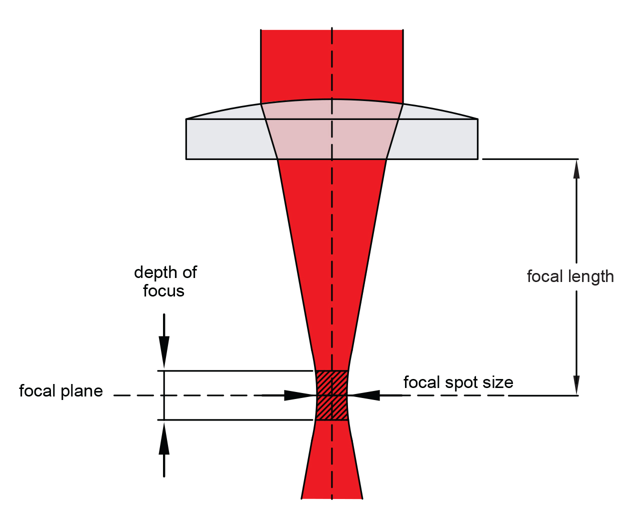
Image taken from LaserGods
Determining the focal length is then done to know the optimal distance from the lens to the material.
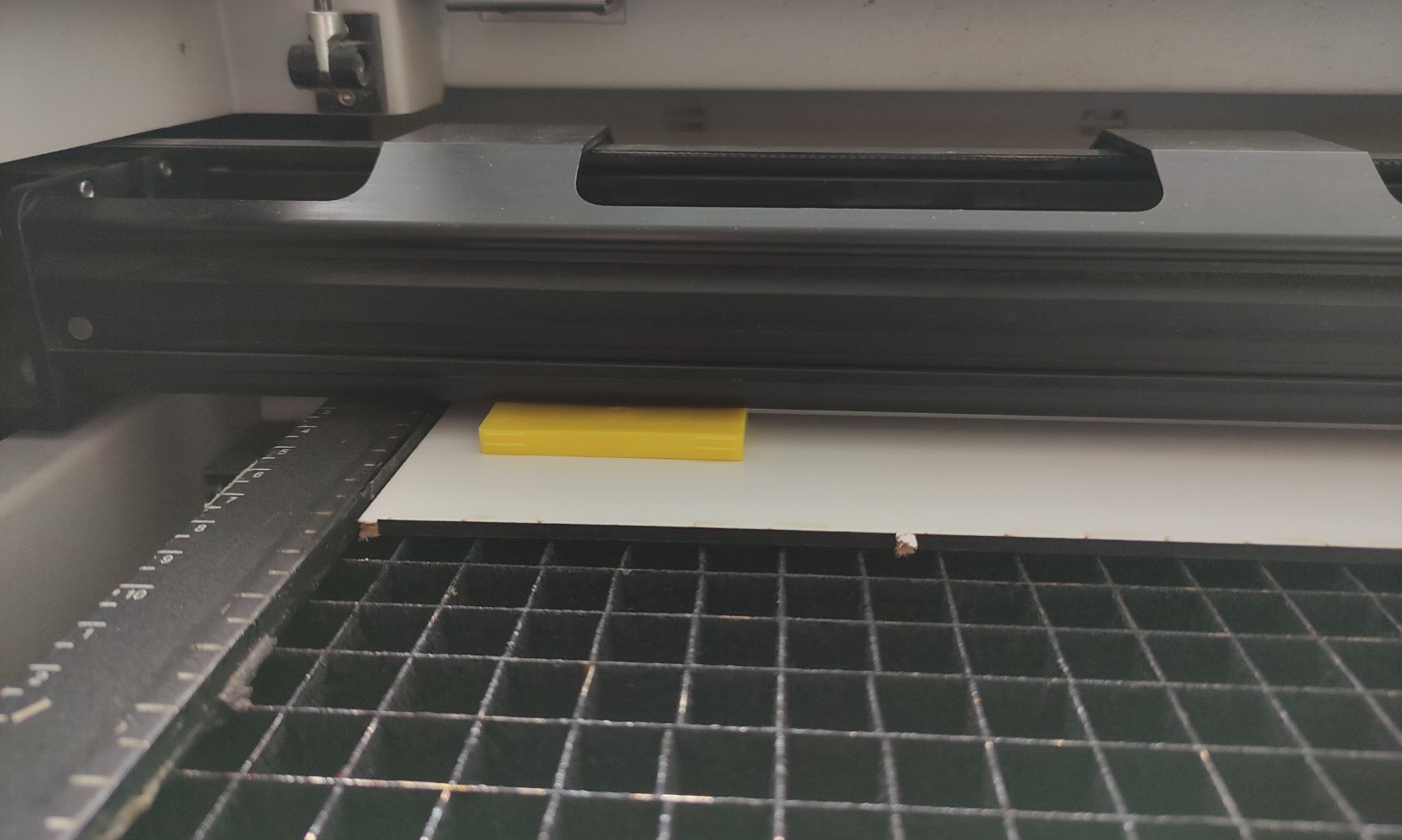
For this task I have used a 3mm MDF piece, making marks based on the parameters recommended in the laser cutter manual:
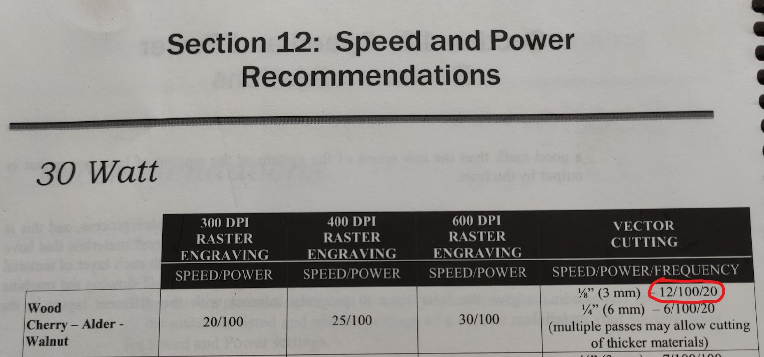
But ☝🏼 since I wanted to make marks instead of cutting, I increased the speed to 100% then:
- Speed: 100%
- Power: 100%
- Frequency: 20
As the lens was not reachable I used a benchmark with a piece of 5mm thick plastic, then I was lowering the bed with the controller:
-
First I made 35mm lines with a focal length from 25 to 67mm from the benchmark, making steps of 3mm from each other:
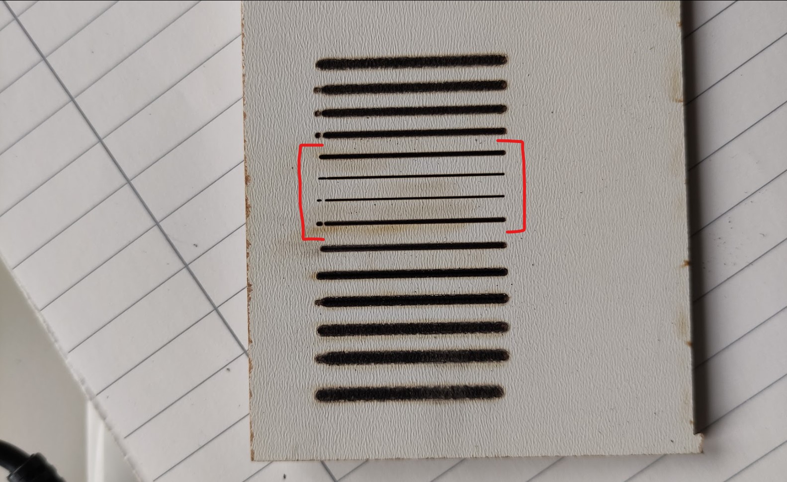
I took the 4 best lines that correspond to the distances: 46, 49, 52 and 55mm from the benchmark. -
Secondly I made 35mm lines with a focal length from 46 to 55mm from the benchmark, making steps of 1mm from each other:
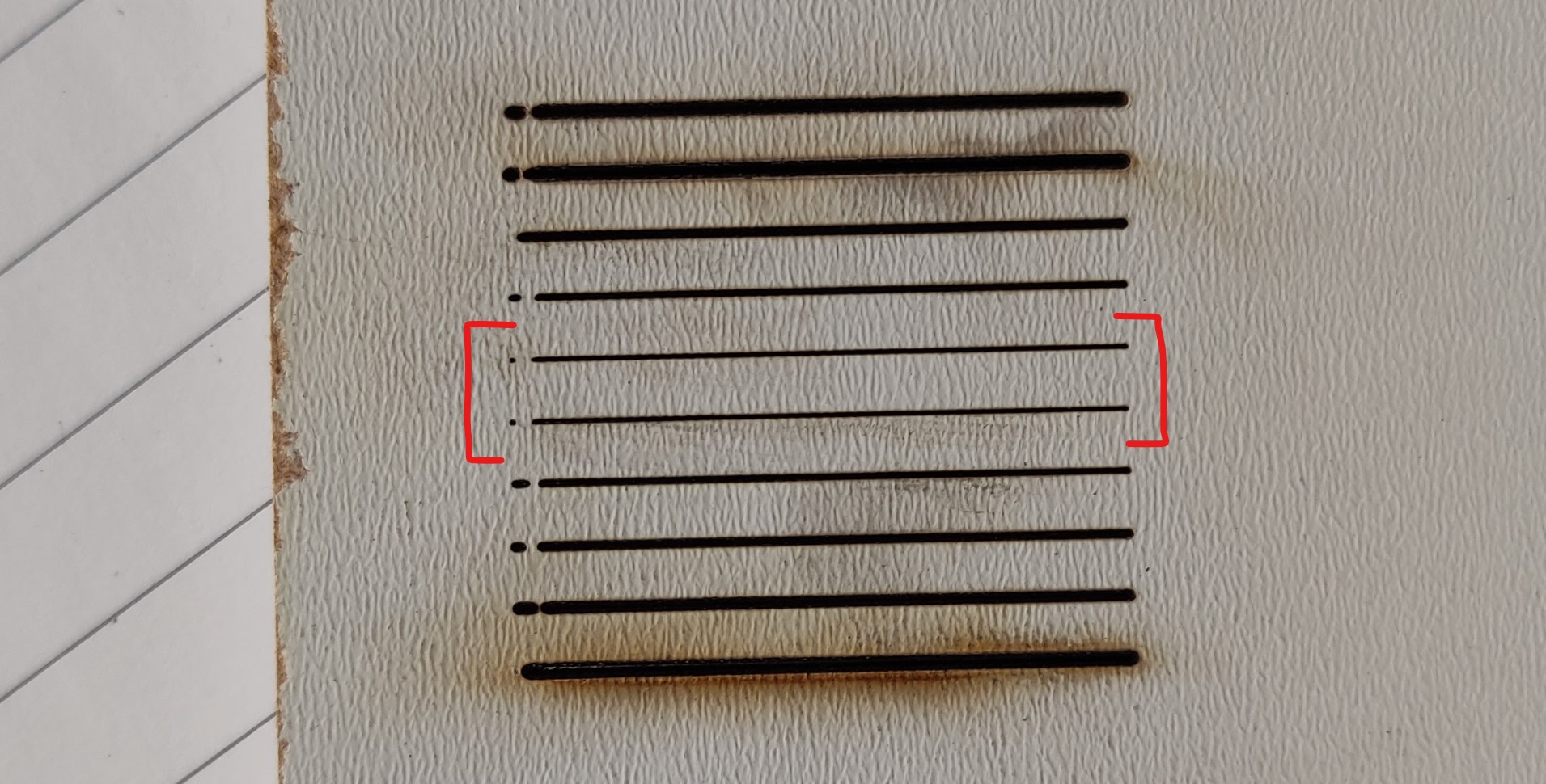
I took the 2 best lines that correspond to the distances: 50 and 51mm from the benchmark. -
Secondly I made 35mm lines with a focal length from 50 to 15mm from the benchmark, making steps of 0.5mm from each other:
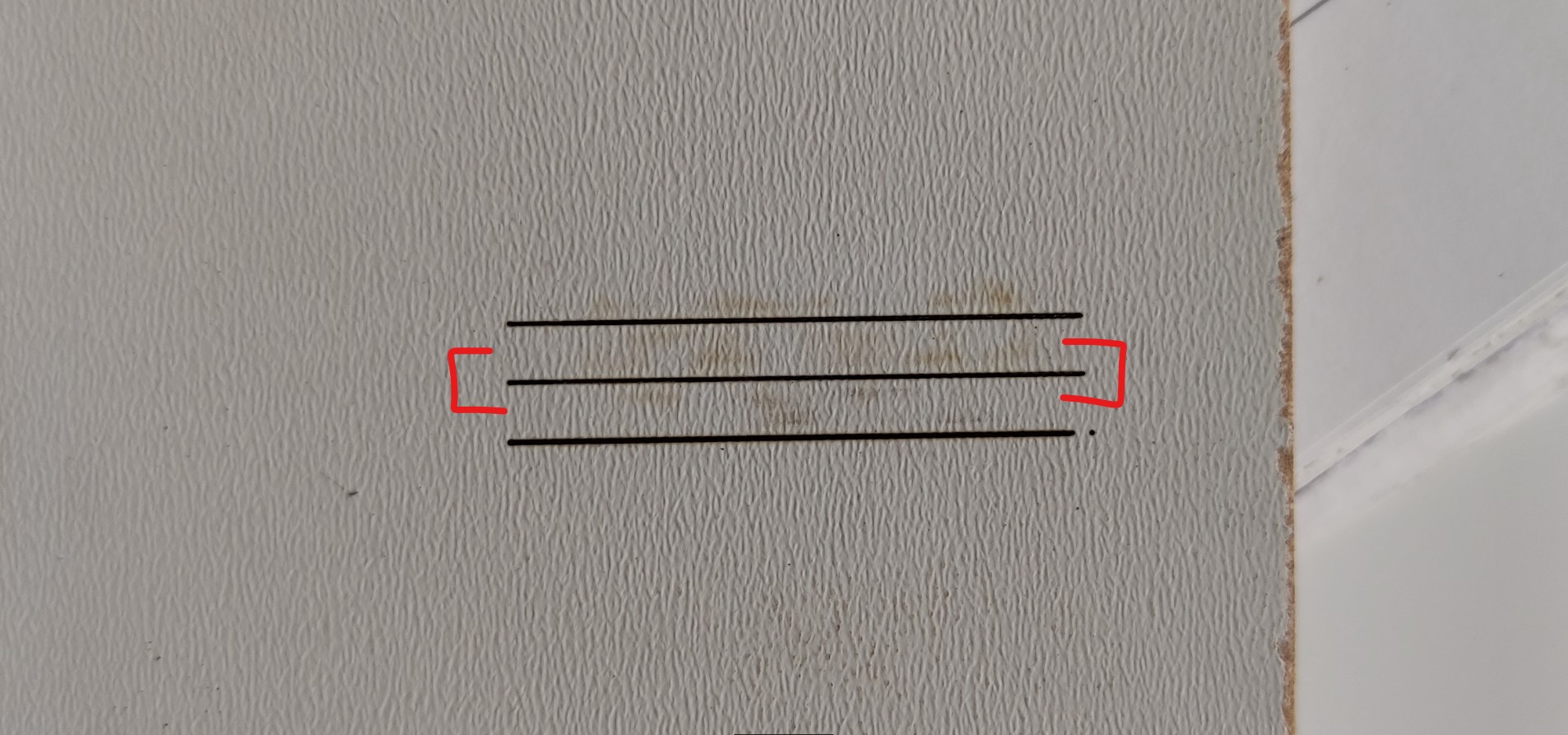
The result was 50.5mm from the benchmark, which is equal to that of the machine focus tool.
Kerf measurement
Kerf is the width of material removed by a cutting process, in this case by the laser. In order to get tight joints, we should take in account this measurement as an offset from the the surfaces to joint in the design.
Since the kerf depends no only on the cutter we use, but on the material properties and the cutting parameters, the best moment to measure it is once we have the official cutting parameters for our project.
In order to measure the kerf, one of the technics consists on cutting some small pieces of the material we are going to use > measure them > compare them with the design measurements:
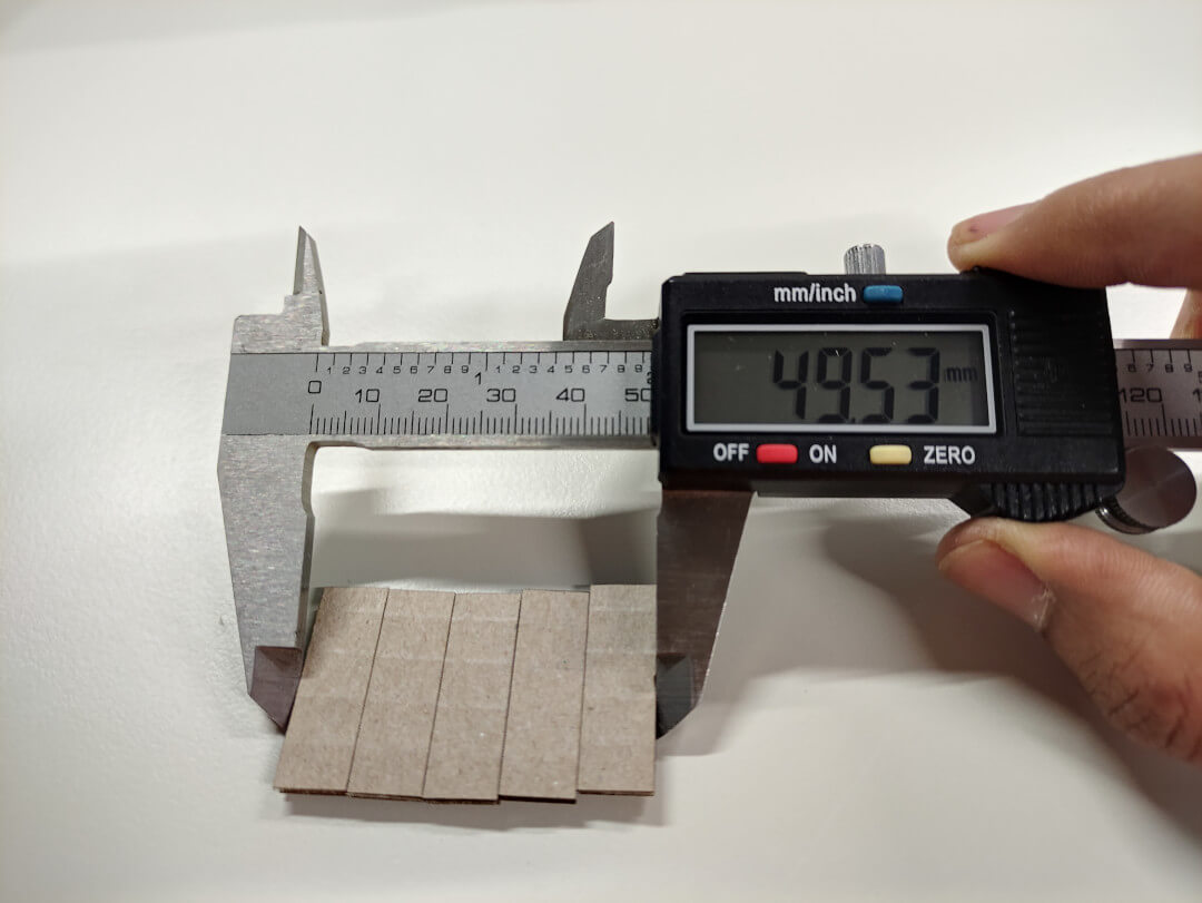
- I cut 5 pieces of 10mm wide.
- Then some calculation:
- Amount of pieces: N = 5
- Designed total length: DTL = 5 x 10mm = 50mm
- Real total length: RTL = 49.53mm
- Kerf = (DTL - RTL) / N = (50mm - 49.53mm) / 5 = 0.47mm / 5 ≈ 0.1mm
This value is applied on the parameters sheet created for the design.
Parameters
These are the processes that we can make in a laser cutter:
- Cutting.
- Engraving.
- Marking.
There are some parameters we need to setup before printing, all of the depend on what process we are going to make, and on the material we use.
- Speed, given in percentage, describes the movement of the laser head. Fast speeds lead to short exposure times, slow speeds lead to long exposure times:
* Low speeds for cutting.
- Power, given in percentage, describes the output power of the laser. 100% is maximum power:
* Low power for engraving.
- Frequency specifies the number of laser pulses per second and is used only for cutting:
* Low frequency = low heat.
Steps
On RhinoCeros
- Open the *.dxf file.
- Multiply and resize images as desired/needed and sort them.
- Setup the cutting:
- Sheet size.
- Set the draw position in the sheet.
- Setup speed, frequency and power.
On Laser cutter
It’s worth to mention that there are two CO2 laser cutters at the FabLab:
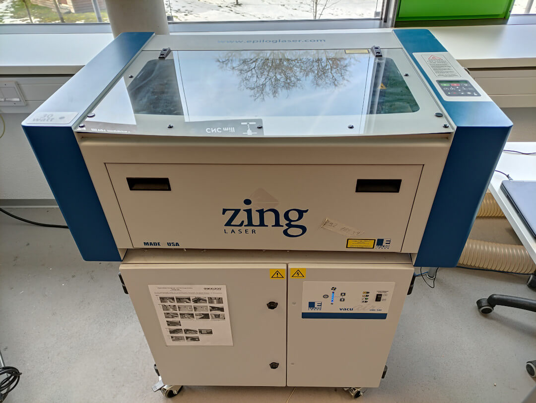
-
Epilog Zing 30 Watts, which we call “The small one”:
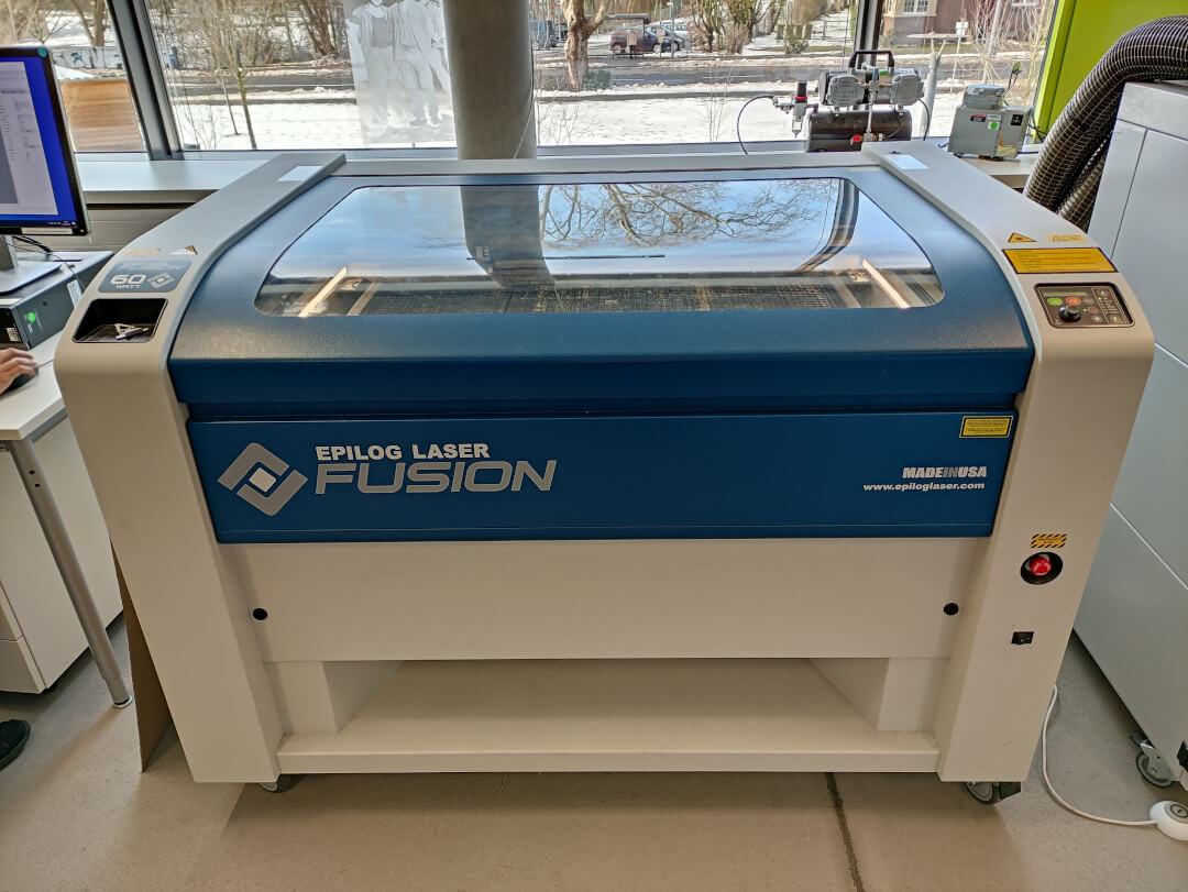
-
Epilog Fusion 60 Watts, which we call “The big one”:
-
Turn on the laser cutter and wait for it to initialize.
- Put the material to cut on the bed and make sure it’s flat.
User control interface:
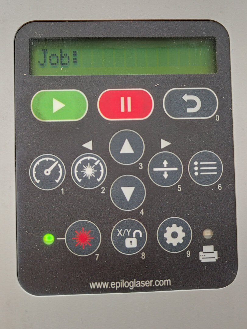
-
Turn on the laser bean:
- Press Button 7.
-
Change home position:
- Press Button 8.
- Move the laser head with your hand.
- Press PLAY.
-
Focus the laser:
- Press Button 5.
- Move the bed using Buttons 3 and 4.
- Use the focus tool, when should barely touch the sheet.
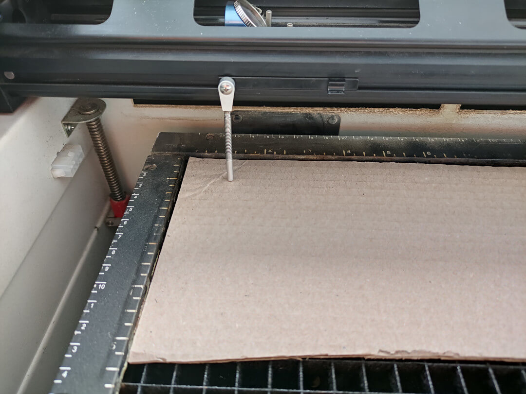
Note: The position of the bed doesn’t need to be kept. When done, lift the tool back to its place.
-
Turn on the vacuum cleaner:
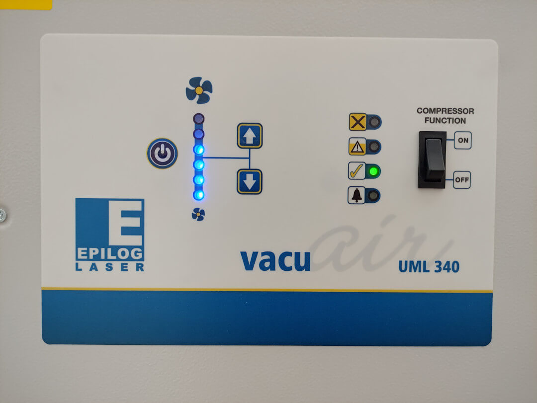
-
Select your file (right now send the file from the computer to the laser cutter):
- Press 6.
- Look for your file using Buttons 3 and 4.
- Press PLAY.
Advice: Once your pieces are cut, wait a few seconds to make sure that the vacuum cleaners sucked all of the emissions which can be more or less toxic depending on the material we use.
-
Take out our parts and remove excess material:
Vinyl cut
Laptop sticker
Heat transfer print
Process steps
The following steps are just the basic ones that I followed, for more details please check the Silhouette portrait - User manual.
On Silhoutte Studio
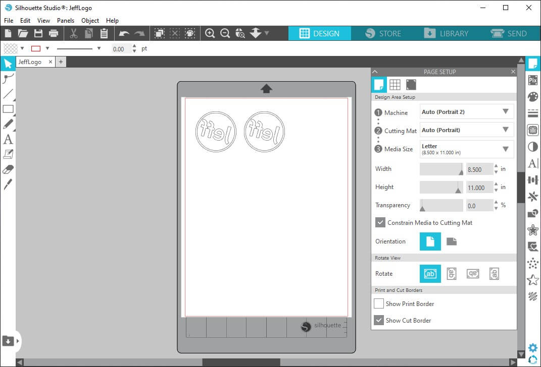
- On the Design tab open the *.dxf file.
- Multiply and resize images as desired/needed and sort them.
- Setup:
- Sheet size.
- Set the draw position in the sheet.
If doing a common sticker, image position would be straight. If doing a print for t-shirt, image position would be upside down.
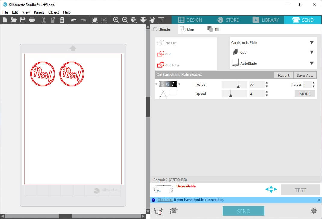
- On the Send tab select process to make on each line.
- Set up the cutting:
- Force.
- Speed.
- Passes.
- Blade depth.
On Vinyl cutter
- Lift the lid.
- Turn the cutter on.
- Put in the material to cut attached to the Cutting mat (right now send the file from the Silhoutte Studio).
- At this point the cutter will automatically start cutting, just wait.
- Take out our parts and remove excess material.
Applications
Stickers
- Just stick it on the surface you want it, but do yourself a favor and avoid bubbles as
Heat transfer printing
You can do this either with an iron or a heat press.
I did it with a heat press.
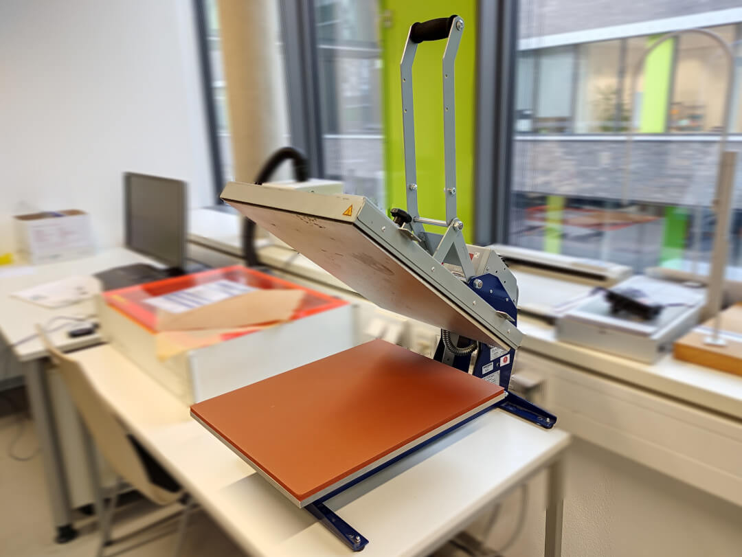
- Turn on the machine.
- Set up temperature and time (I used 135ºC and 20secs).
- Wait for it to heat up, in the mean time…
- Put the cut piece on textile.
- Place it on the sponge.
- Put on the Heat transfer paper.
- Once it has reached the set temperature…
- Lower the heating plate using the Handle (a countdown will begin).
- Once the set time passes, it will emit an alarm type sound.
Assignment outlook
The assignment is generally about two techniques, but since I have done different things with different materials I really need to talk about each one individually.
The Key chain… was rather the simplest one I would say 🤔, but still looks very interesting.
The construction kit… it was more funny than useful 😅, for constructing real prototype bodies you need to make specific shapes for what you want to make; I share the idea of cardboard os a nice and cheap material for this purpose.
Stickers made of vinyl… lovely, easy, intuitive, with a lot of possible applications.
Heat transfer print… my favorite part of this assignment, I stayed rather simple when it comes to colors and design (cause well, I just wanted to make a t-shirt with my name), but it opened my mind for further work with this technique in the future. If there’s something that I recommend for it would be:
- Make sure you mirror the design.
- Check the recommended time and temperature for each textile you use.
- Also make sure you cut the right side of the thermoplastic.
Files
- Parametric design:
ConstructionKit.f3d
- Laser cutting:
KeyChain.dxf
- Vinyl cutting:
JeffLogo.dxf