- Remote control
Circuit
This section has been pre-worked during my Input devices and Embedded Networking and Communications assignments.
Components:
- Microcontroller board:
1x Vehicle-RemoteControl board ,whose documentation is in the next section
- Input devices:
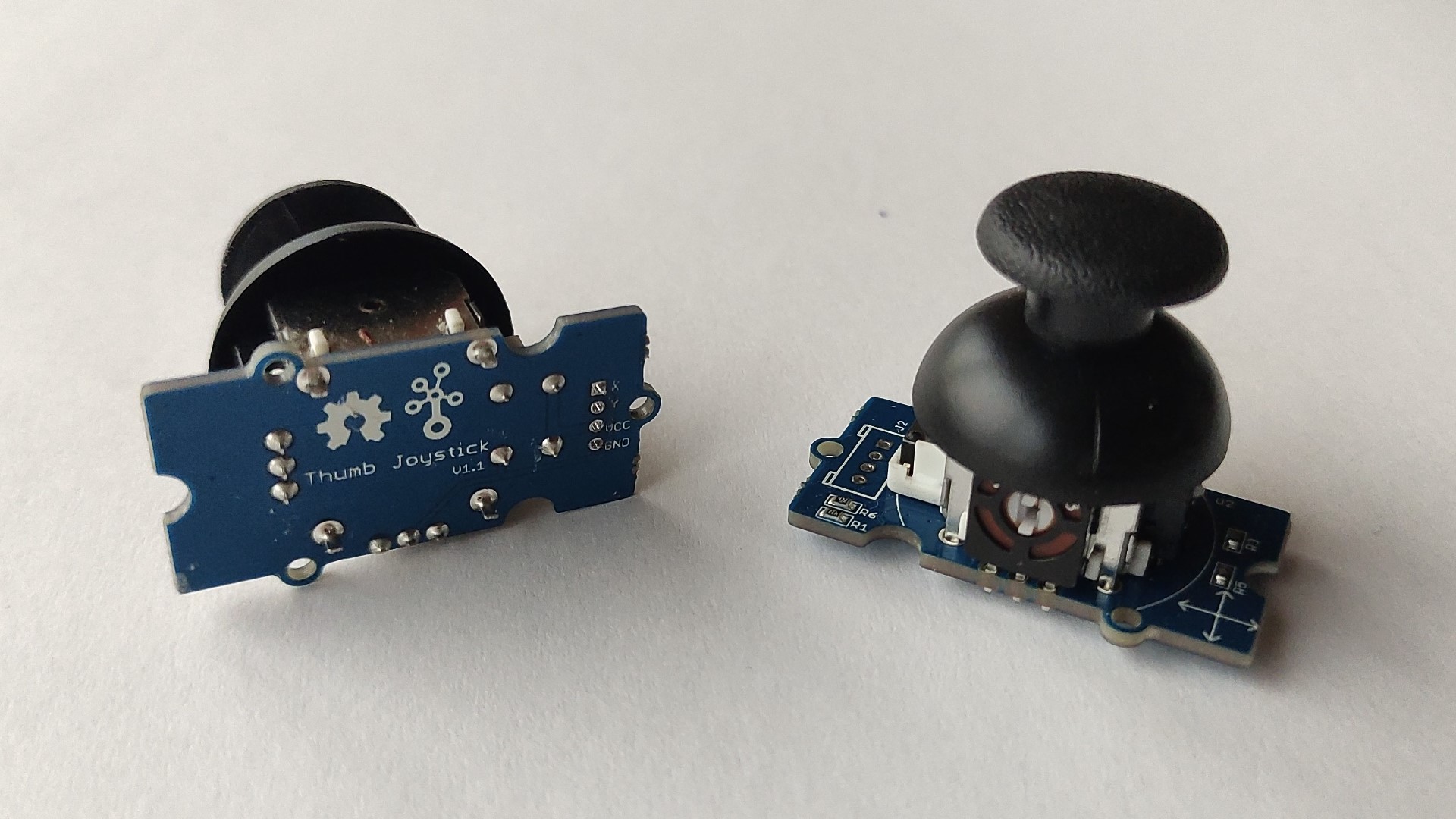
The input devices I used to control the movements of the vehicle were Joysticks cause with them I can give direction and also control the speed depending on the percentage in which it is pressed.
2x Grove - Thumb Joystick v1.1: this is a 4 pins Joystick:
- Wireless communication:
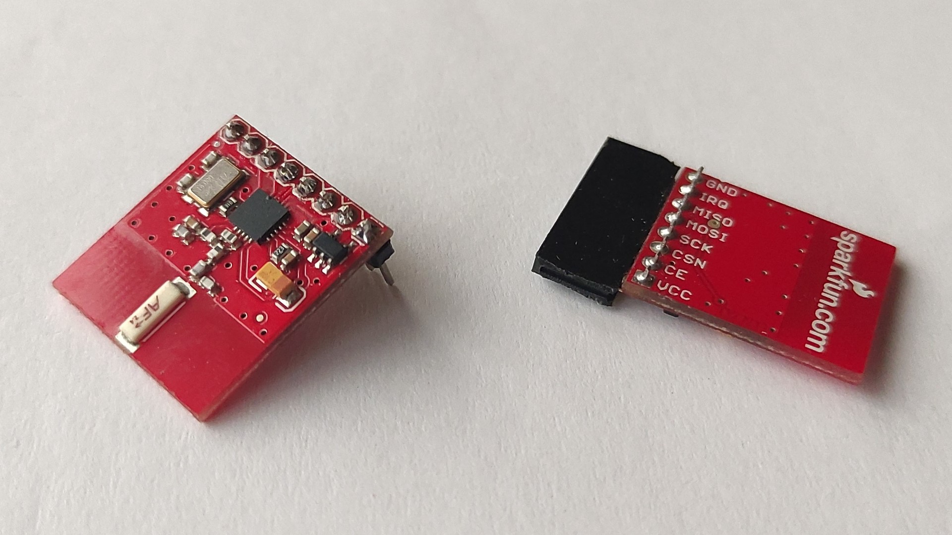
1x nRF24 module: this one has the antenna on board; I have also replaced the pin header to adapt it to me needs/idea:
- Power:
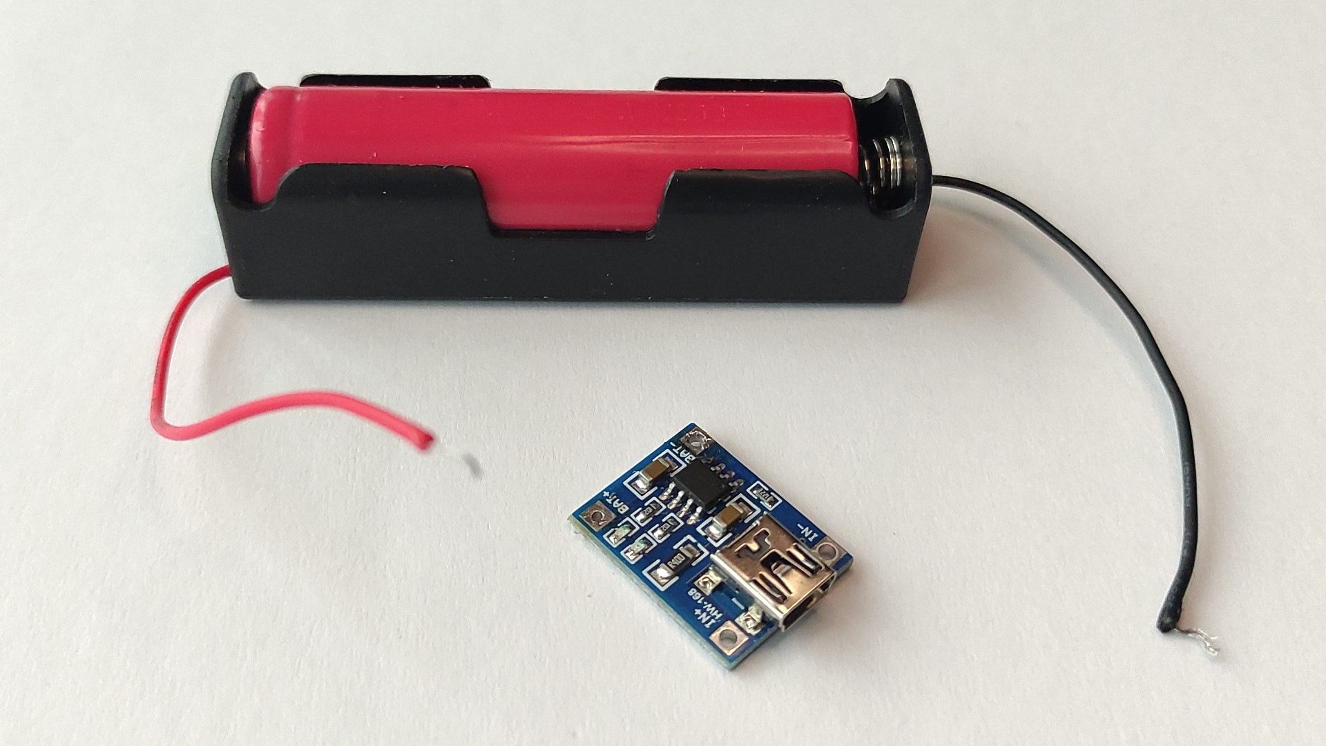
1x UR18650 Li-Ion Battery 2600mAh 3.7V: a single-cell Lithium-Ion battery, with its battery holder and HW-168 charging module:
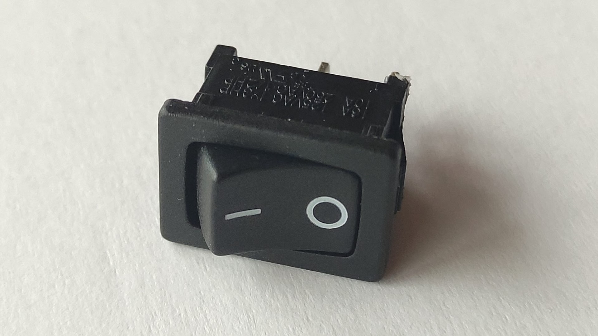
1x On/Off switch:
Vehicle-RemoteControl board
Requirements, considerations and component selection:
It’s worth mentioning first that I wanted all of the boards for my final project to be double sided.
Since I need three basic movements (X-Y and rotational movements) I used two Joysticks.
- I used an ATtiny1614 microcontroller cause it has the necessary pins and memory for this application.
Image taken from SpenceKonde.
- I used a nRF24 module for communication, then I have arranged pin headers for connecting this module.
- A 3.3V voltage regulator (since the nRF24 module works at 3.3V, the Joysticks can work at 3.3-5V, and also the ATtiny1614 can work at that voltage).
- 1uF capacitor for voltage stabilization.
- A LED (with a 499Ω resistor) to indicate that the board is getting energy.
- UPDI + VCC + GND connection for programming and powering my board.
- I have used the footprint of TH pin headers for the Joysticks.
- I have used TH pin headers to connect both sides of the boards, as a solution to not having rivets on hand.
Schematic
For electronics design I have used KiCad.
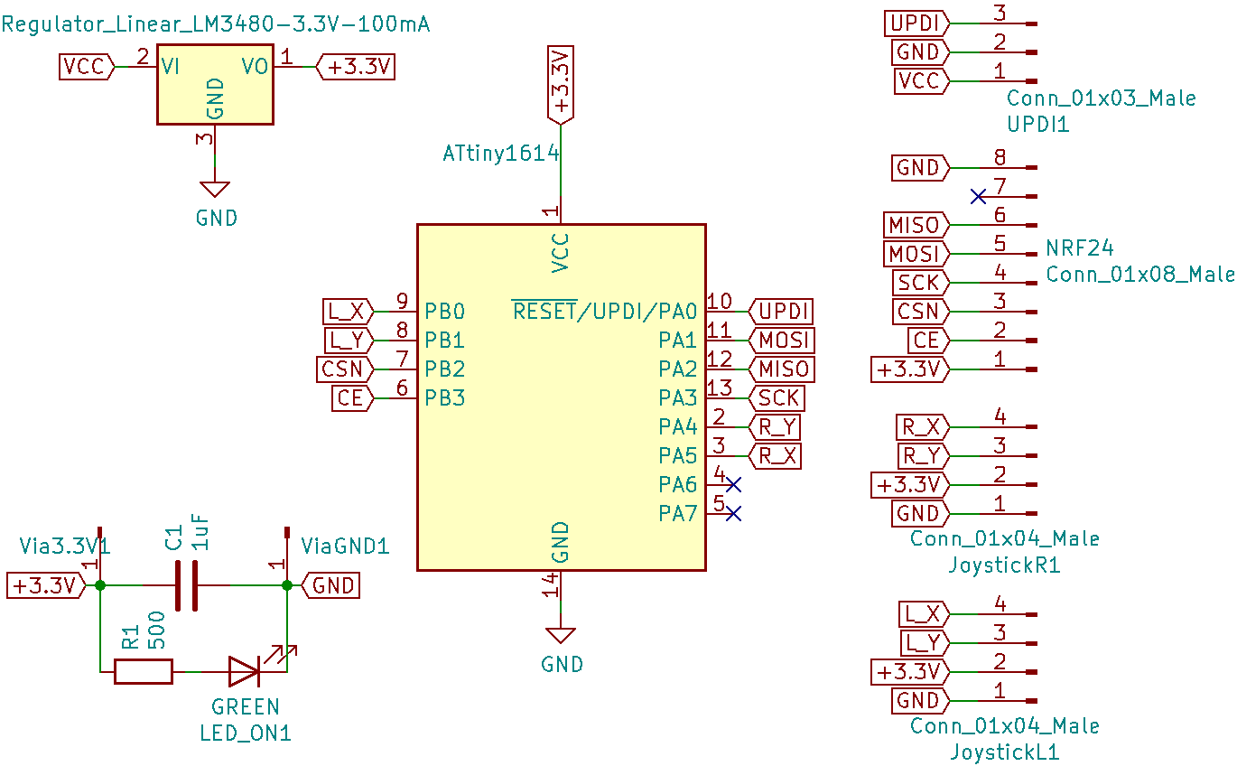
Even when I only need three inputs from the four that I can get from the Joysticks, I connected all of them so it could be used also for drones where besides Pitch, Roll and Jaw, you control Altitude.
If rivets are available, delete “Via3.3V1” and “ViaGND1” pins from Schematic and put the rivets instead in the Board layout.
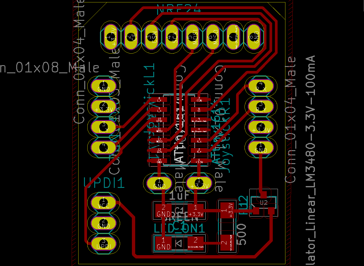
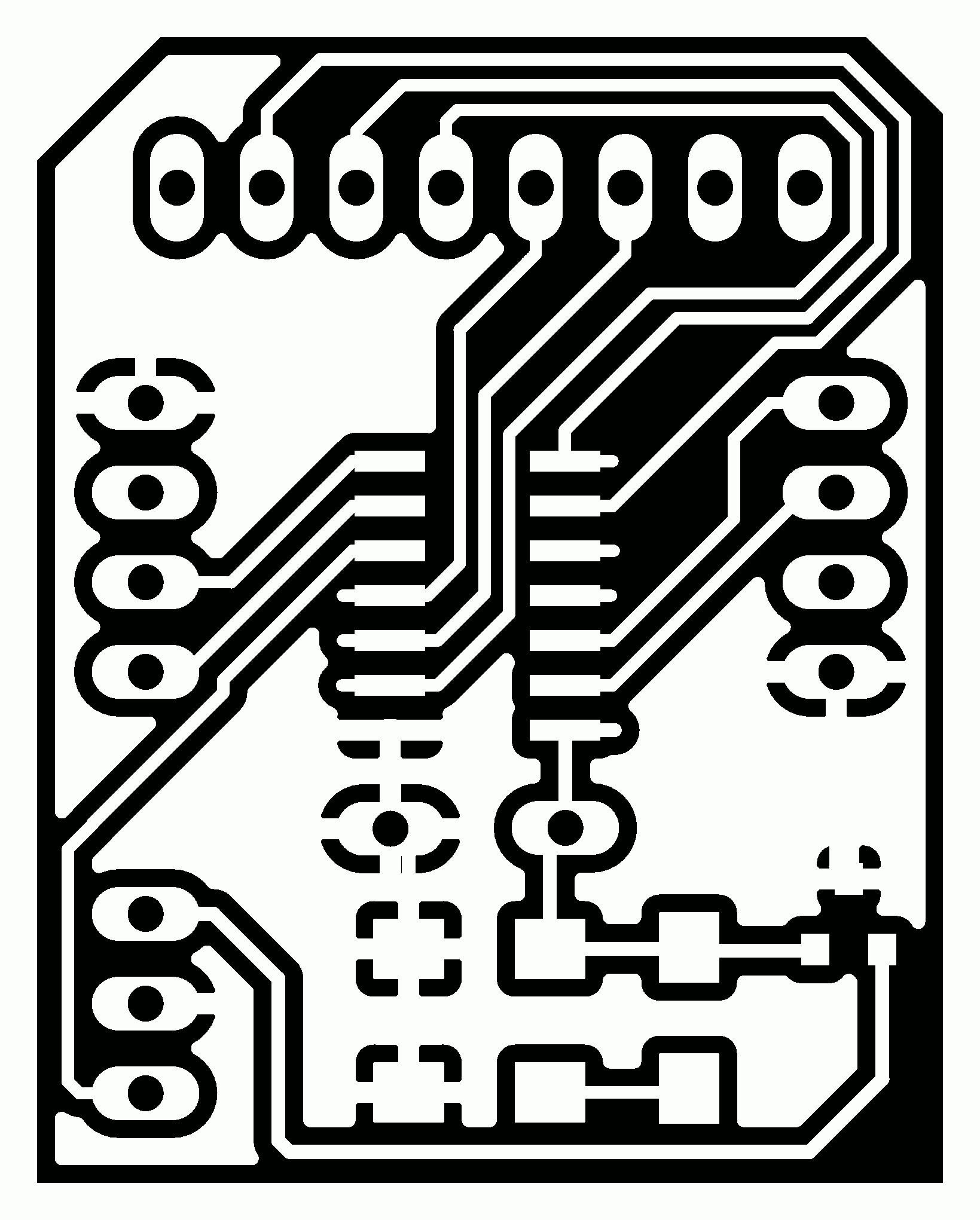
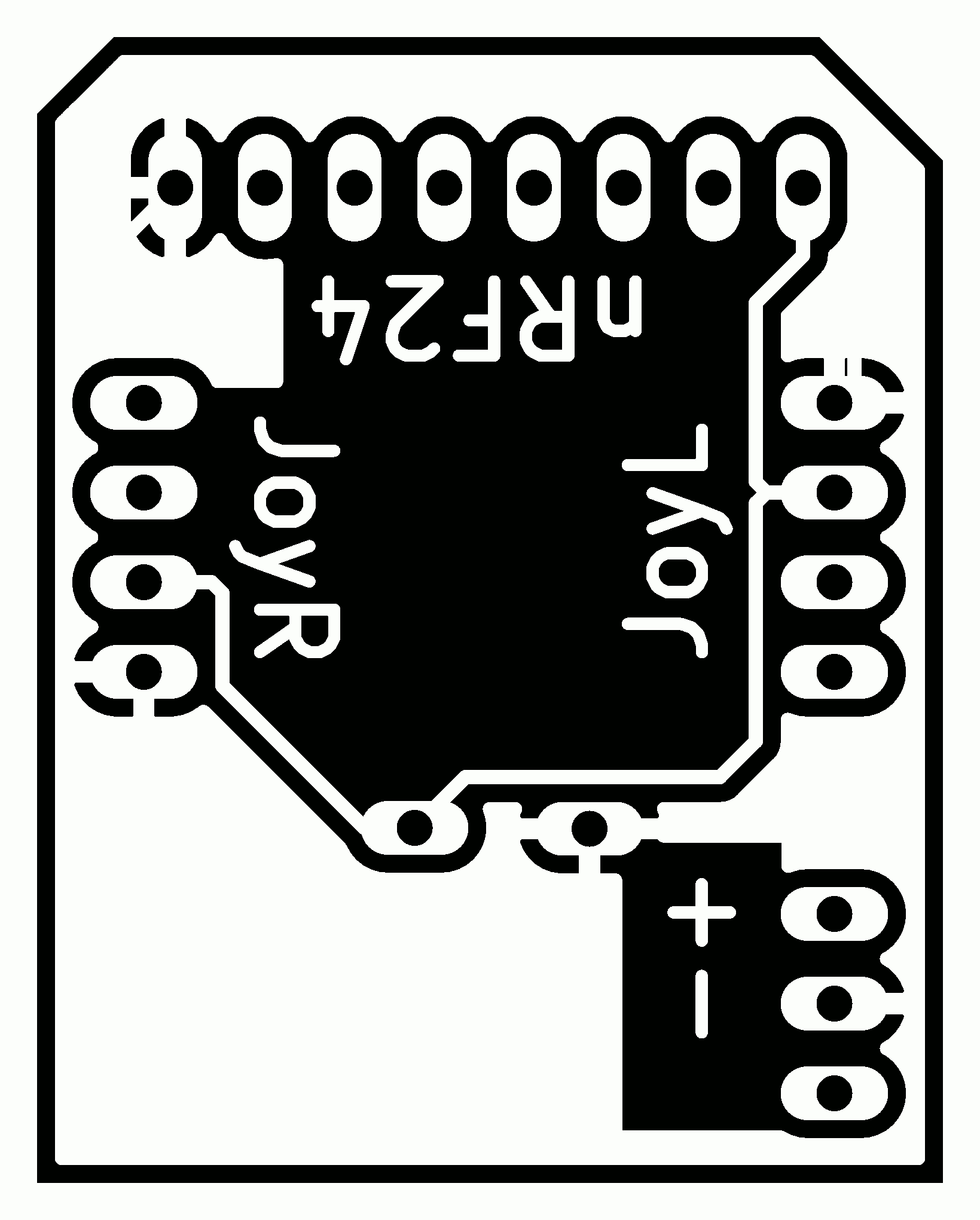
Board layout
I used the front layer mainly for logical connections and the back layer for Power connections.
-
Front side:
-
Back side:
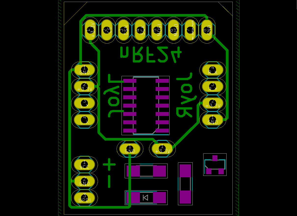
Eventually I have used “Add filled zones” as GND.
I have exported the images as SVG, then I prepared them using Inkscape and GIMP and exported them as PNG with DPI=1500.
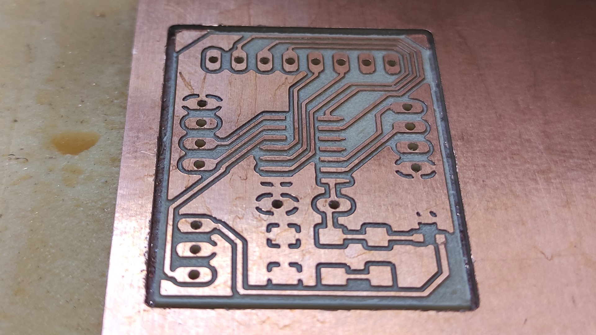
Milling
I have manufactured the by milling.
Images:
I have milled the front side first, where I cut the outline:
- Traces:
- Outline:

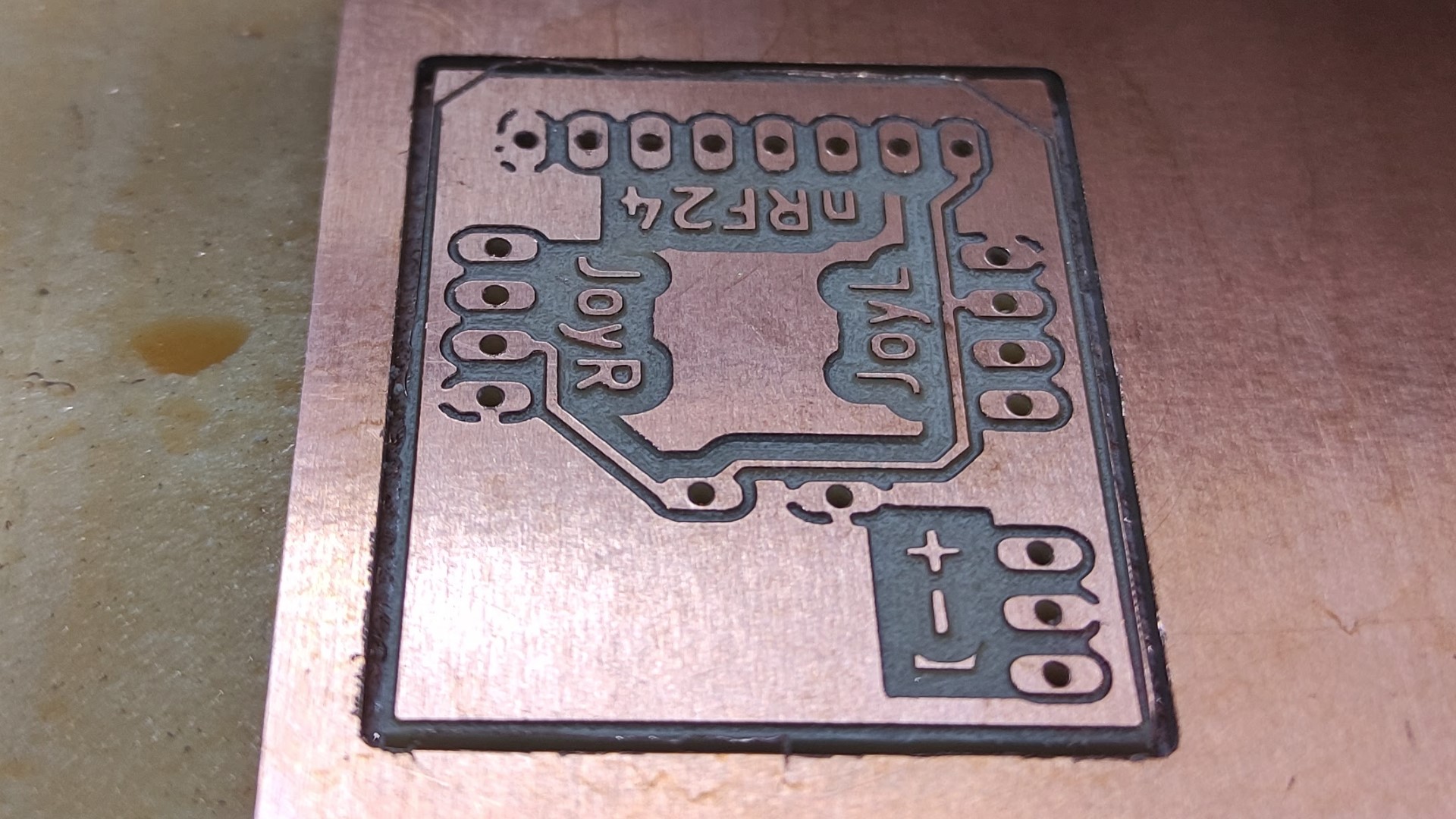
Eventually I milled the back side, where I drilled the holes:
- Traces:
- Holes:

Afterwards I have generated the g-code using FabModules.
Milling process:
- The milling machine I used was the Roland MonoFab SRM-20.
- The tool I used was a V-bit 0.2-0.5mm.
- The double sided PCB was FR1.
-
Front side:
-
Back side:
Soldering
List of Components:
| Qty | Component |
|---|---|
| 1 | ATtiny1614 microcontroller |
| 1 | LM3480-3.3v voltage regulator |
| 1 | 1uF capacitor |
| 1 | 499Ω resistor |
| 1 | LED |
| 19 | Single row right-angle male pin header |
| - | Cables |
- I have added some FLUX SK 10 as a final protective layer..
Programming
Preparation
First settings
For the first time we need to add the MegaTinyCore to the Arduino IDE:
- Open the Arduino IDE.
- File > Preferences
- Paste the following link in Additional Boards Manager URLs: http://drazzy.com/package_drazzy.com_index.json
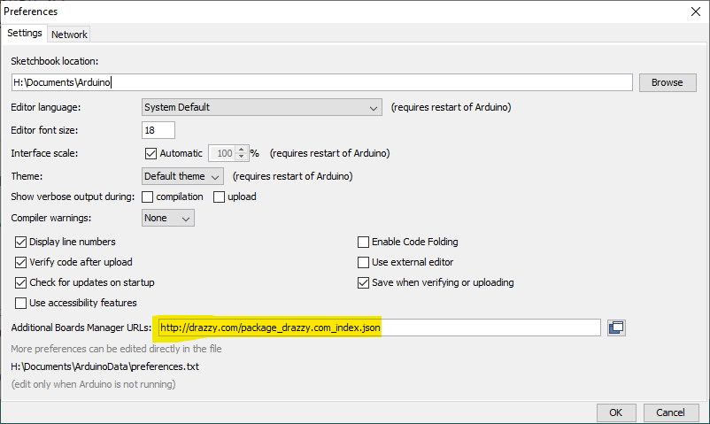
- Press OK
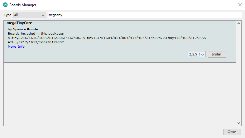
- Tools > Board > Boards Manager
- Search for _MegaTinyCore (by Spence Konde):
Connecting board to PC
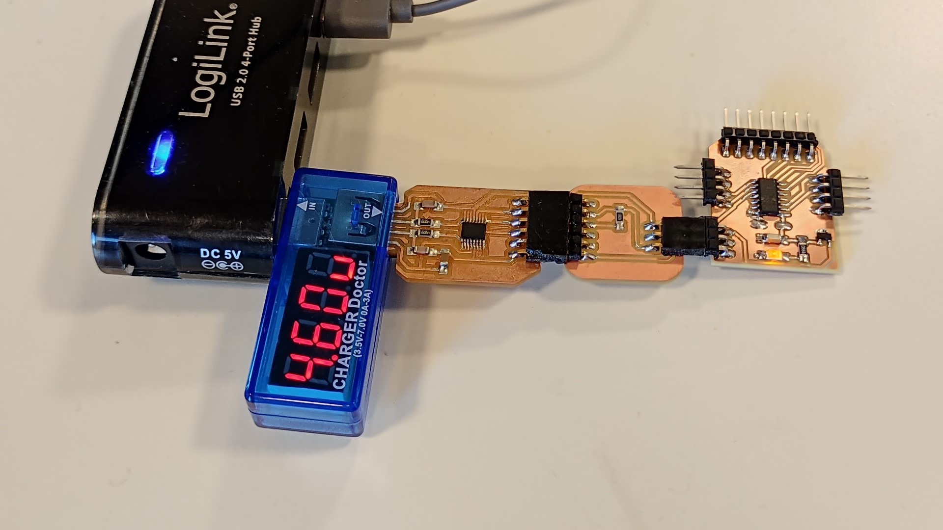
For programming the board I used the USB and FTDI-UPDI adapter boards that I made during the Electronics production assignment:
Upload a Code
-
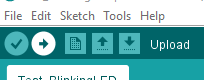
To upload a code to the Board, we just need to use the following highlighted settings in the Arduino IDE:
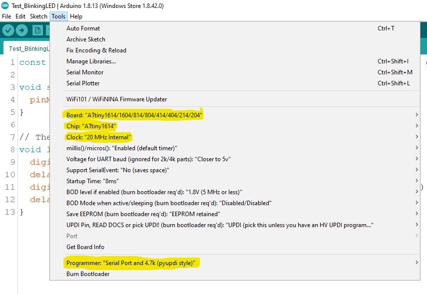
-
After selecting these options and when using the microcontroller by the first time, press Burn Bootloader to setup the Microcontroller; then you can just press the Upload button:
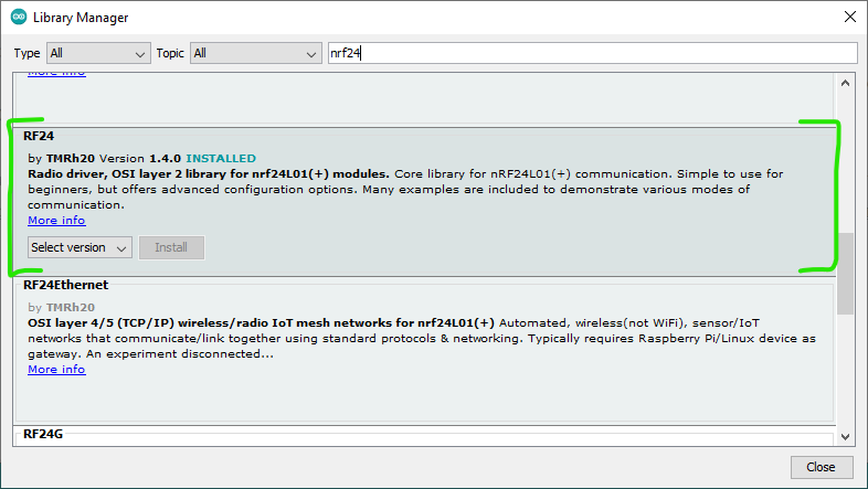
Download libraries:
Beforehand, it’s needed to install nRF24 (by TMRh20):
Code block
1 2 3 4 5 6 7 8 9 10 11 12 13 14 15 16 17 18 19 20 21 22 23 24 25 26 27 28 29 30 31 32 33 34 35 36 37 38 39 40 41 42 | |
Find a video of a simple test with this code here.
Frame
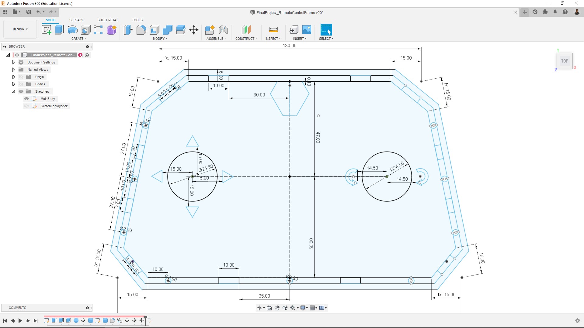
Design
For designing I used Fusion 360.
Since I was already made the Robot final design, making the remote control wasn’t a big deal:
- My Idea was having the horizontal movements on the right and rotation on the left, and I wanted to make them with engrave, but an engrave in the back side. As the acrylic is transparent I could se is from the other side and I looks nice to me, to the design had to be a mirror of the desired result:
Laser cutting
Further information about a laser cut process in my Computer controlled cutting assignment.
- For setting up the cutting I used RhinoCeros:
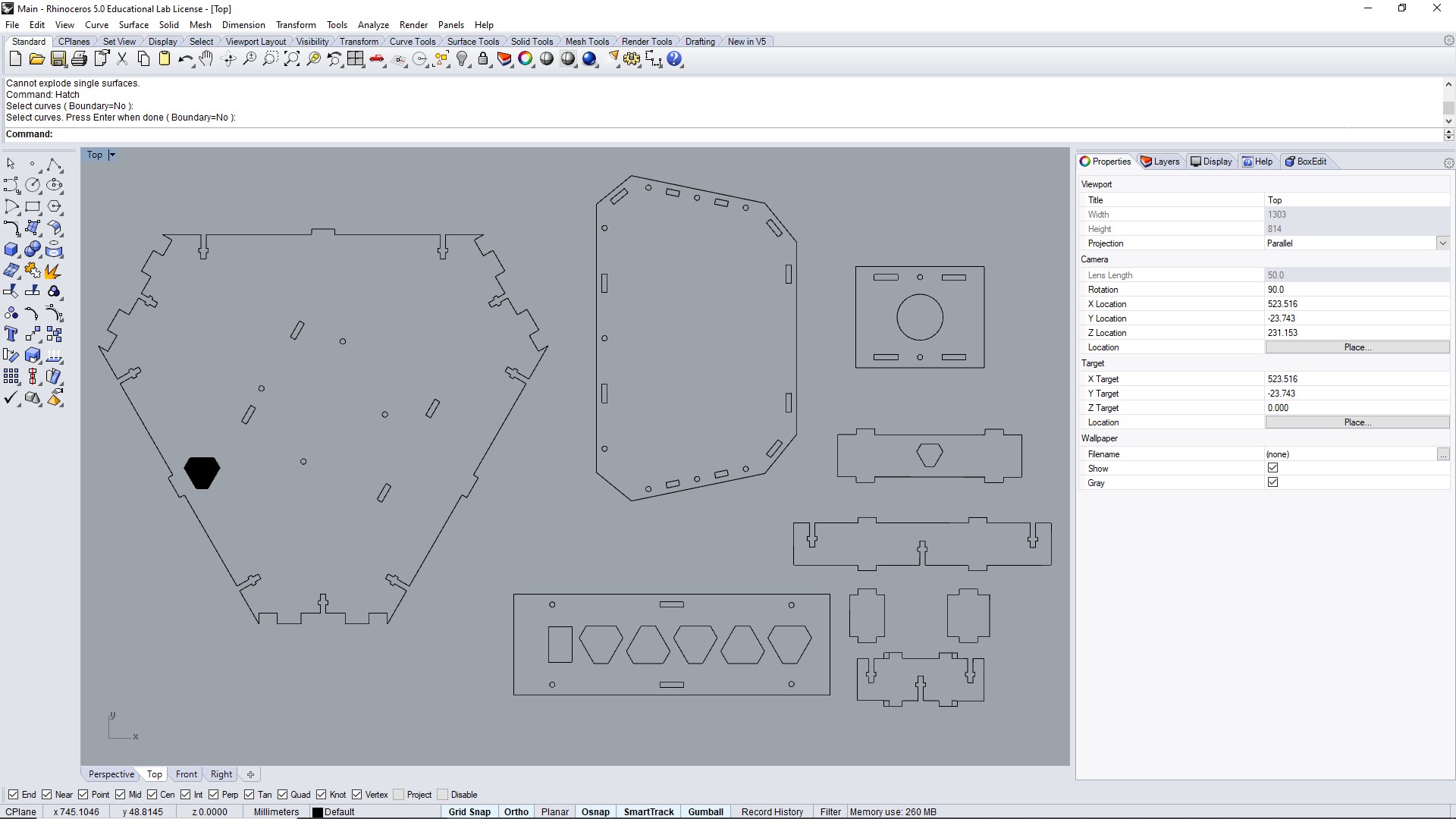
- The laser cutter I used was the Epilog Zing 24 - 30 Watts.
- Parameters used:
* Engrave: Speed: 100%, Power: 25%
* Cut: Speed: 40%, Power: 100%, Freq: 5000Hz
Note: I have cut the pieces together with the Robot frame.
Result:
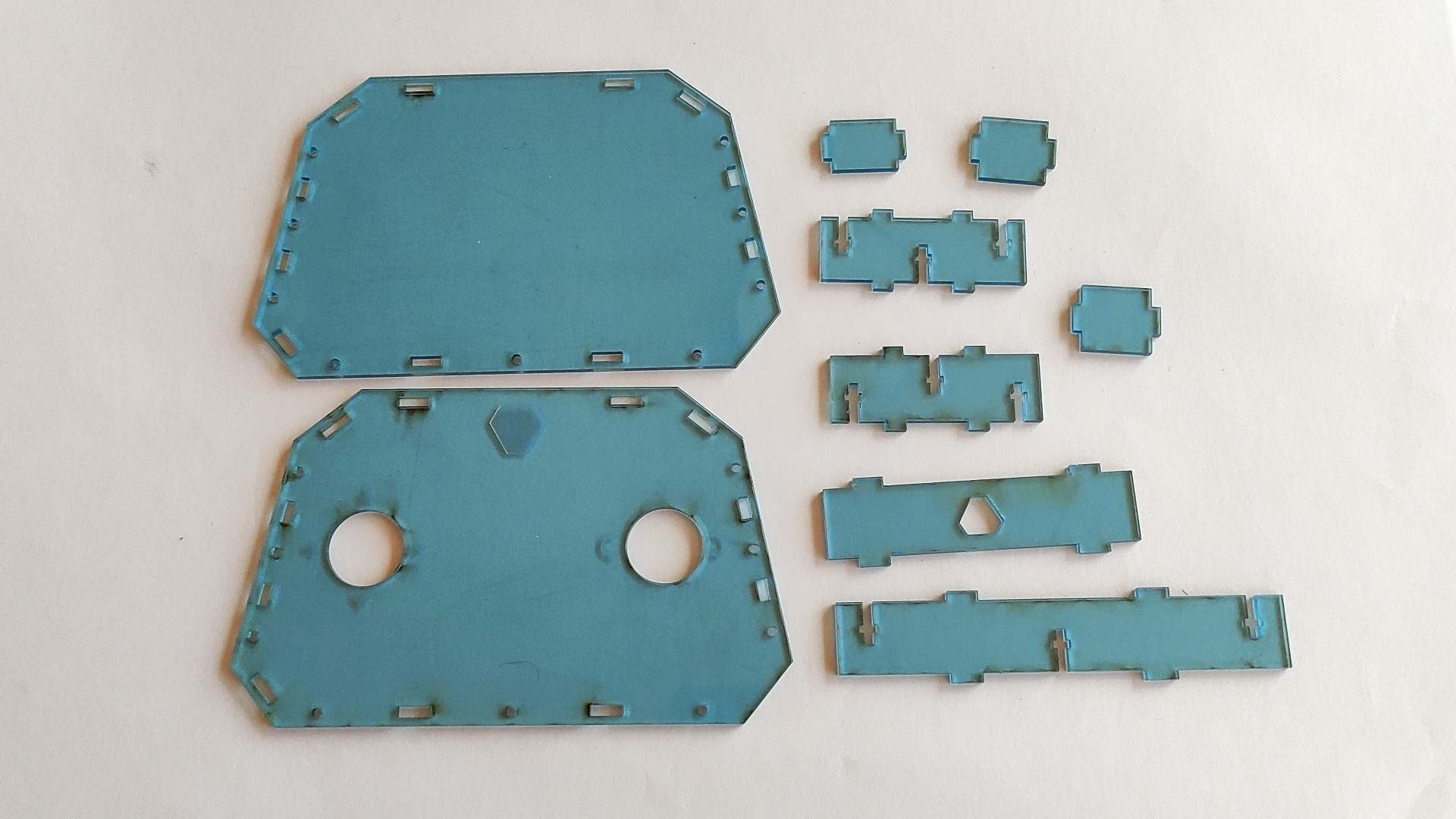
Note: At this point I wasn’t removed the transparent film from the acrylic yet, that’s what looks burned from the laser cutter.
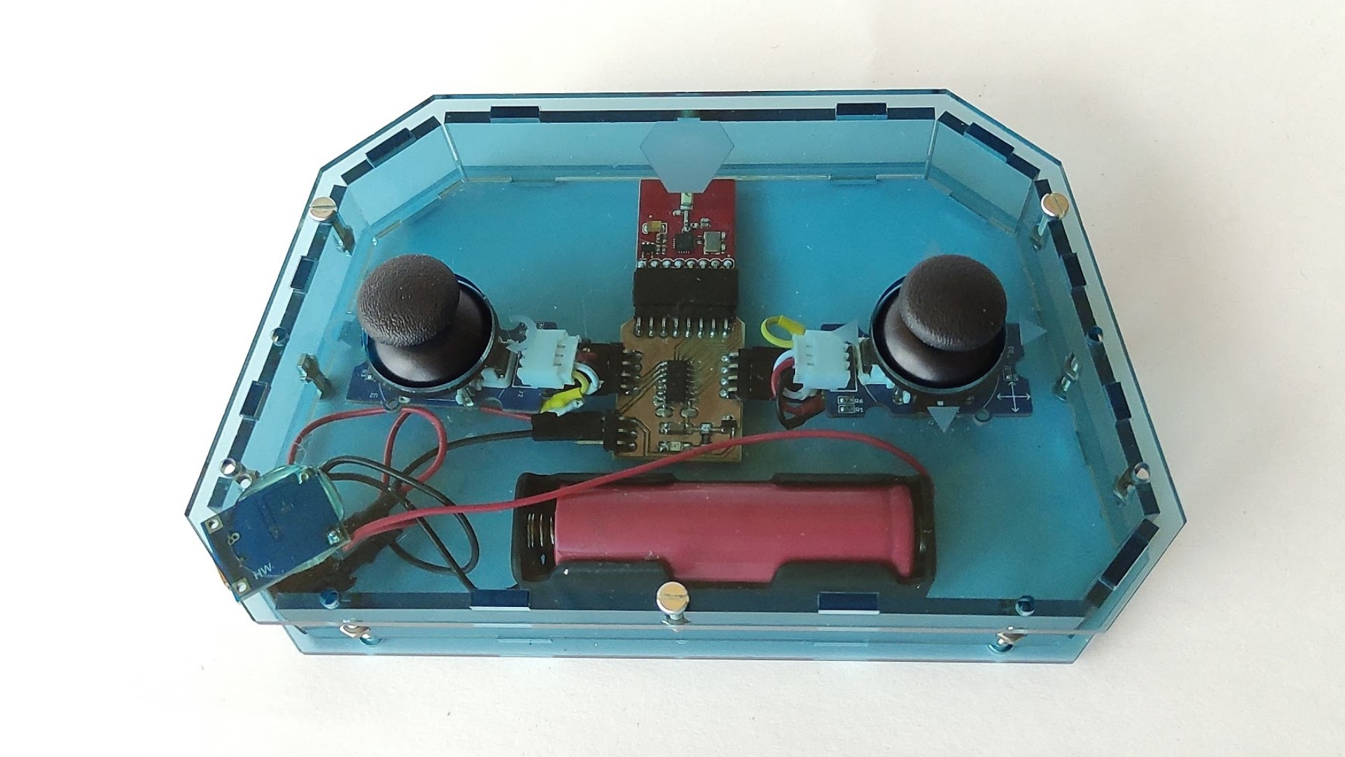
Assembly
At the end, it was just a matter of putting everything together. The frame was assembled using M3 bolts and nuts:
Files and references
KiCad project:
RemoteControlBoard.zip
Arduino Code:
RemoteControl.ino
2D Sketch:
RemoteControl.dxf
Datasheets:
- nRF24 Radio transceiver
- ATtiny1614 Microcontroller