10. Mechanical Design, Machine Design | Vinyl cutter
- Design a machine that includes mechanism + actuation + automation.
- Build the mechanical parts and operate it manually.
- Actuate and automate your machine.
- Document the group project:
Group assignment page: here.
We have made a vinyl cutter machine.
- Document your individual contribution:
Everything started with a couple of meetings with our instructors to decide the machine were going to make and schedule its development.
My individual contribution
3D design
I did a project in Fusion 360 to which I added my colleague and instructors:
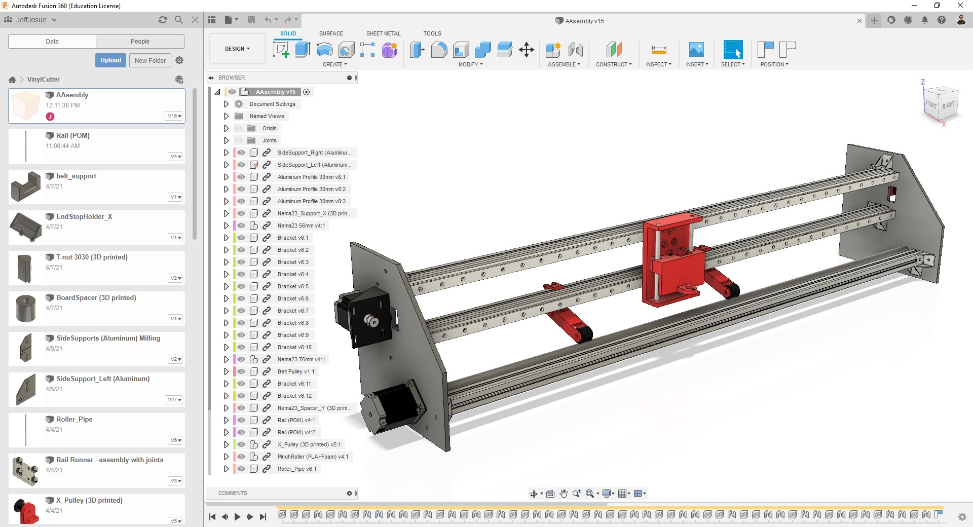
I did most of this part:
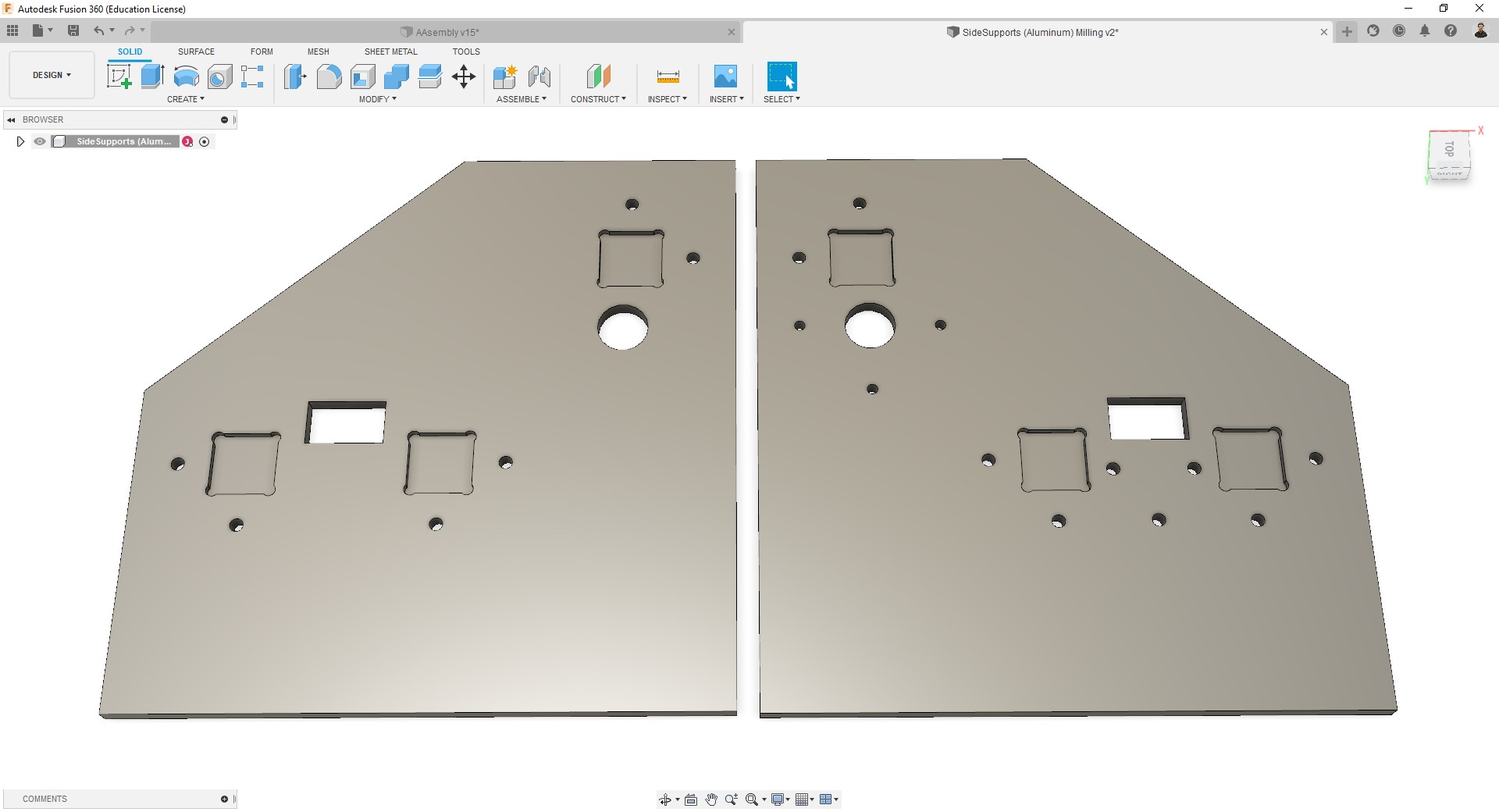
- The side supports, which I worked the hardest on.
- Motor holders.
- Coupling to connect the roller with the Y axis motor.
- I modeled the motors, aluminum profiles, linear rails, rail runners, roller, and brackets.
- Since we were missing two T-nuts I have also modeled it for 3D printing.
- I have also made the 3D assembly.
-
Side supports:
-
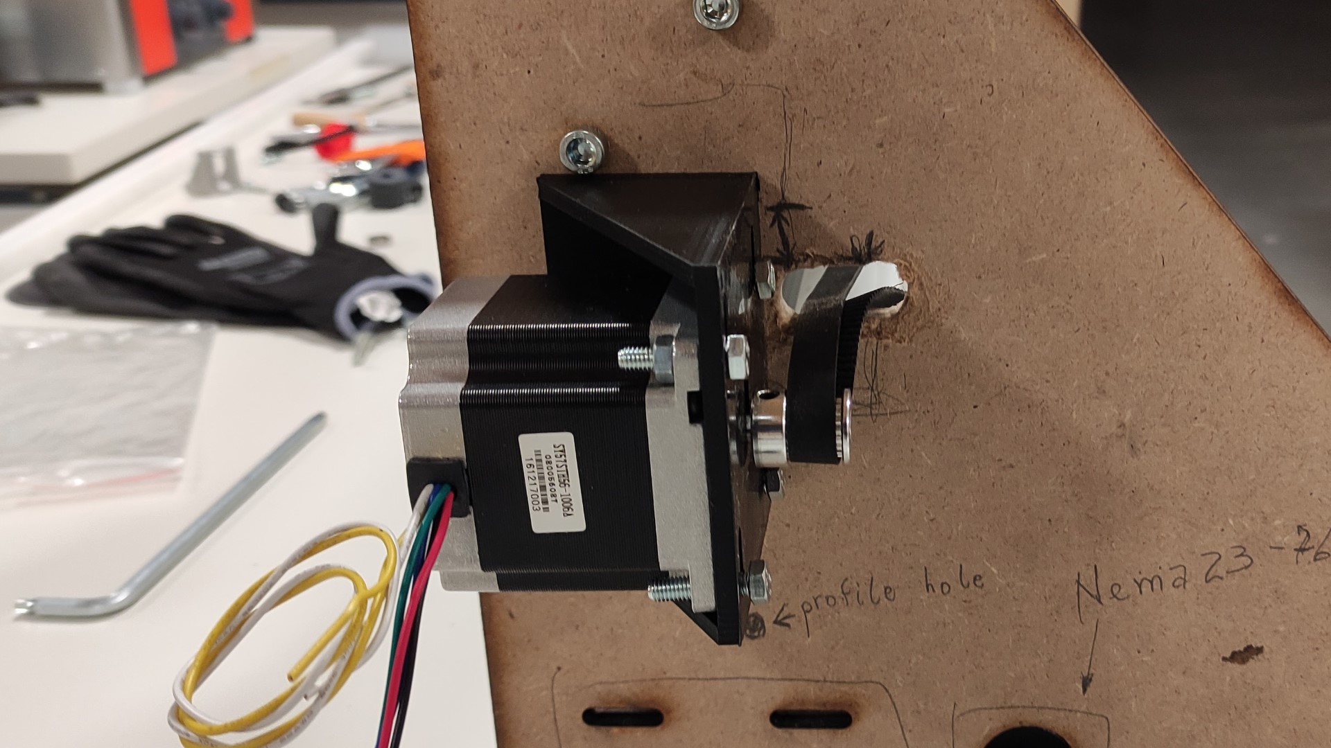
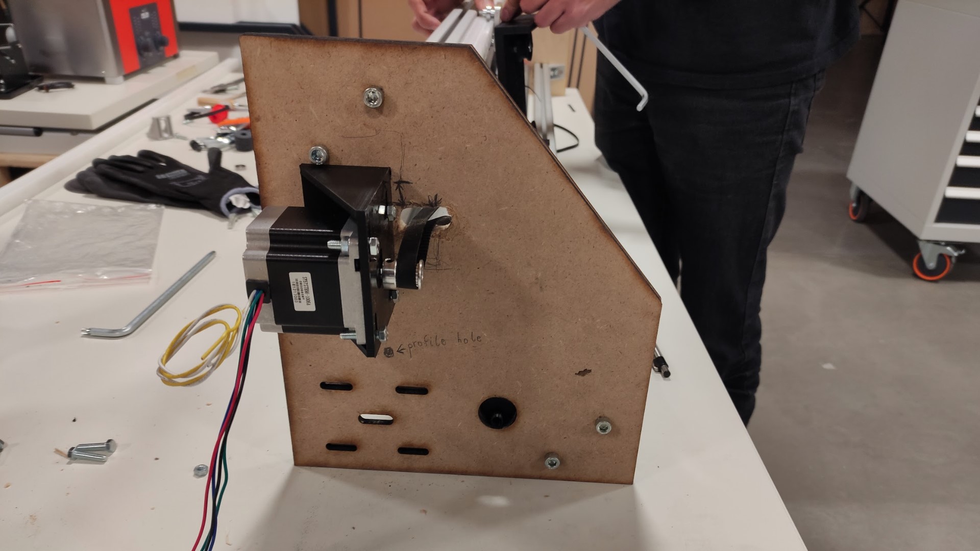
Nema23 holder:
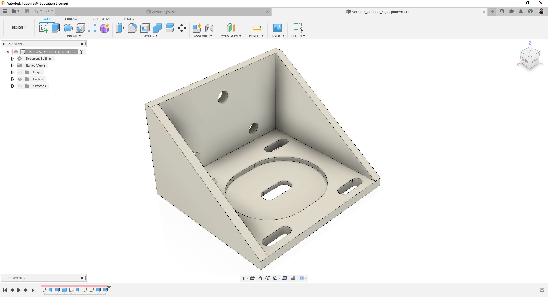
This design offer a no-fixed position for the motor, so you can move it by a distance of 1 cm. -
T-nut:
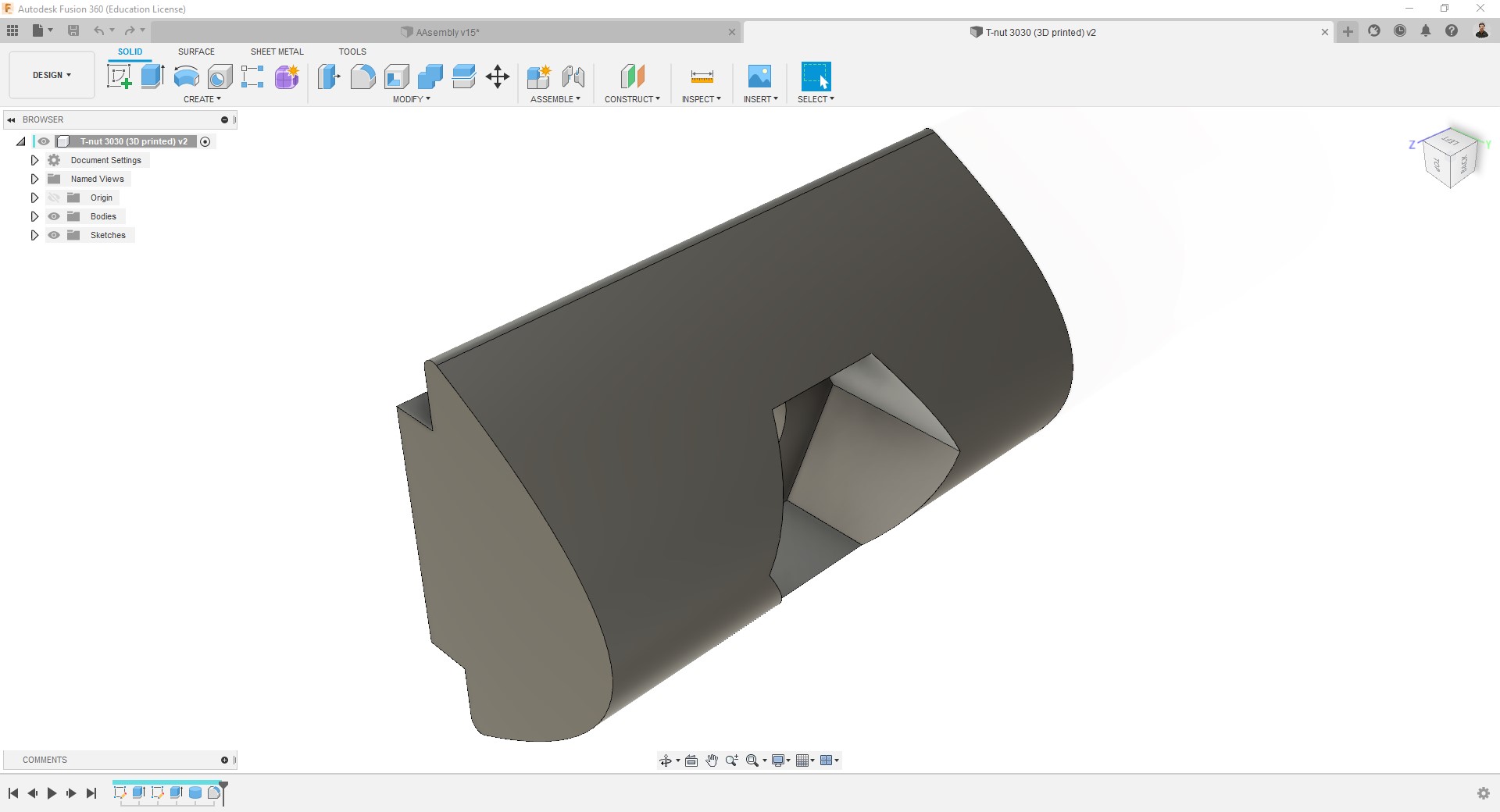
This model includes includes a pocket to introduce a M3 nut. -
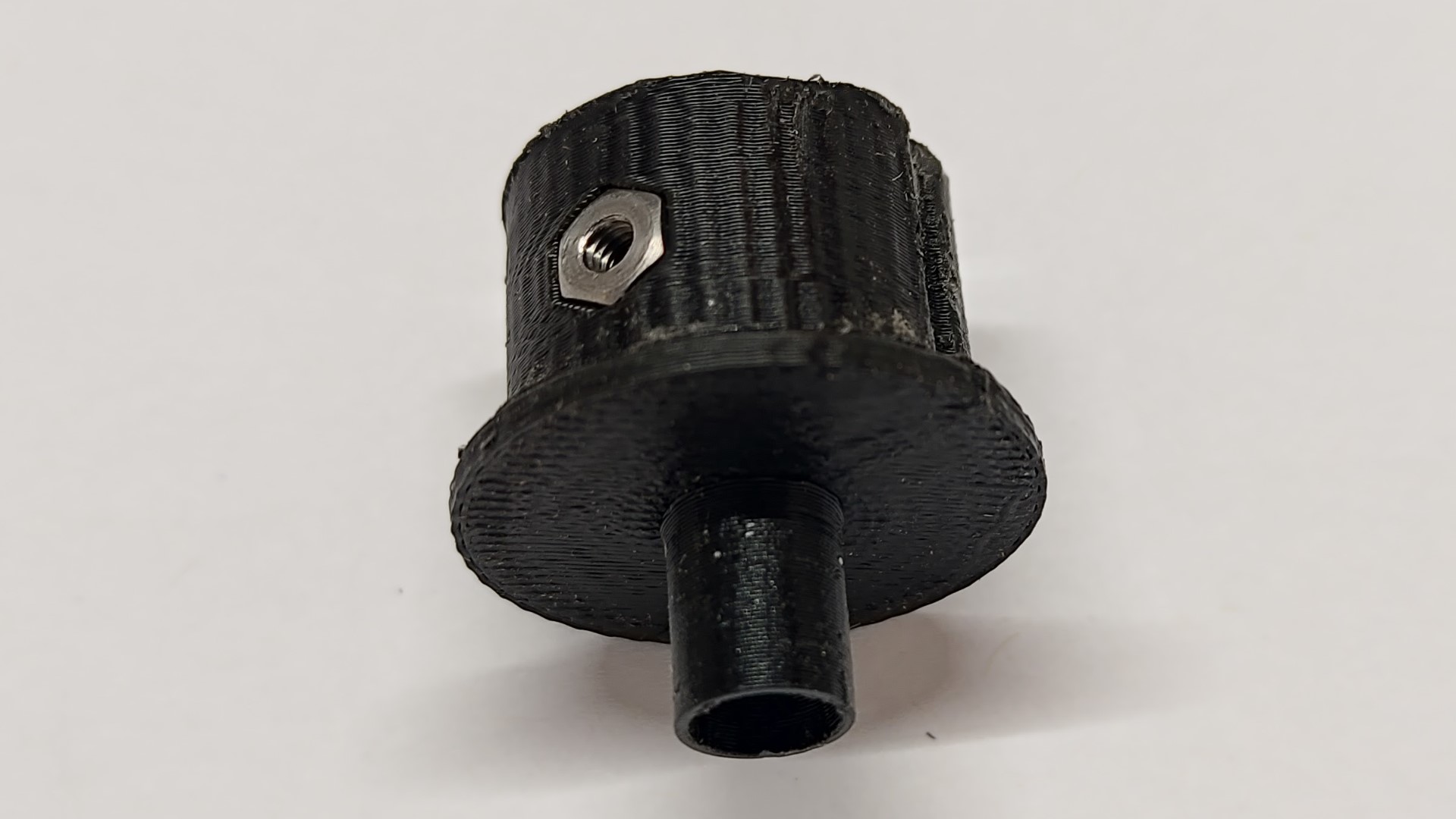
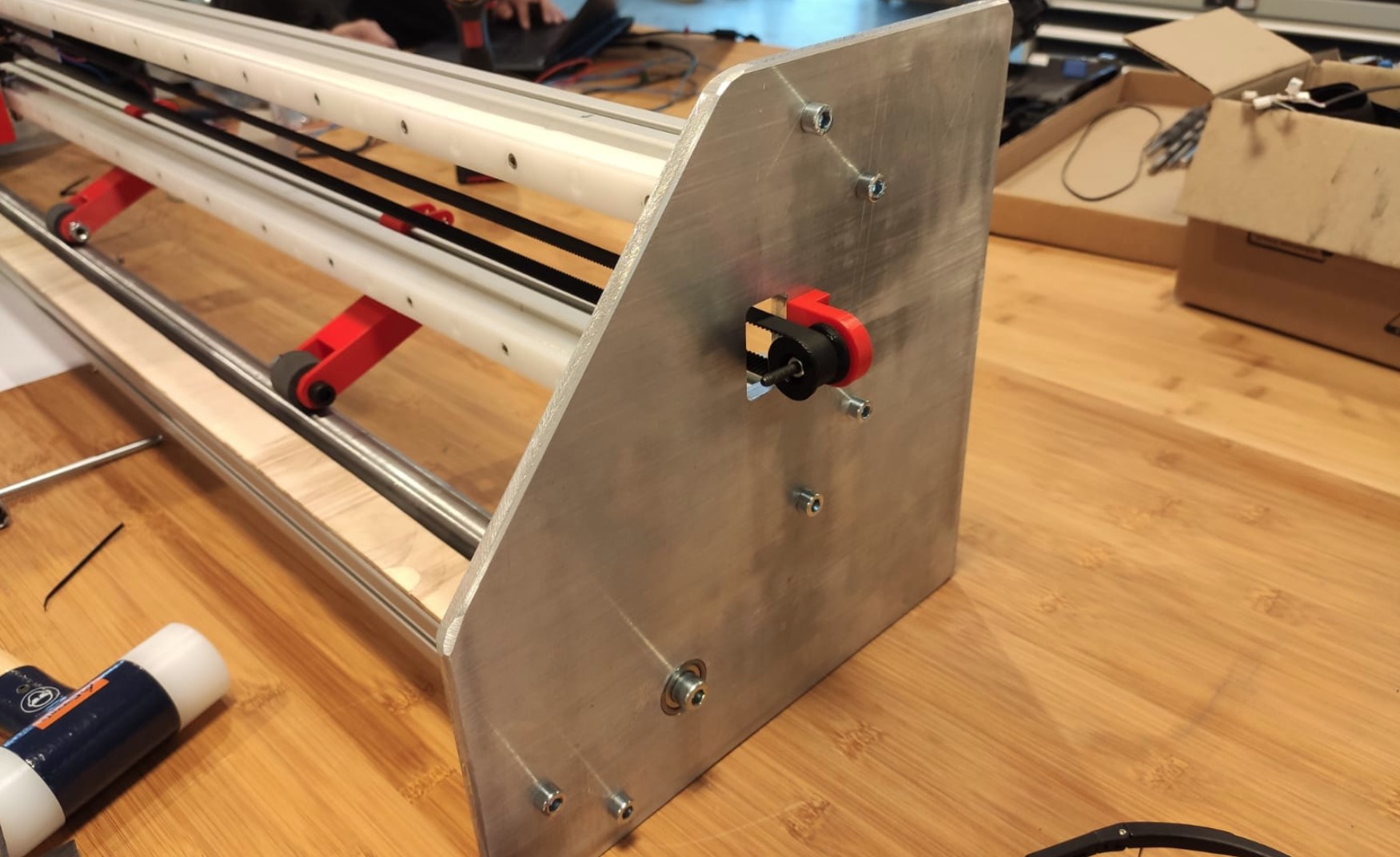
Coupling:
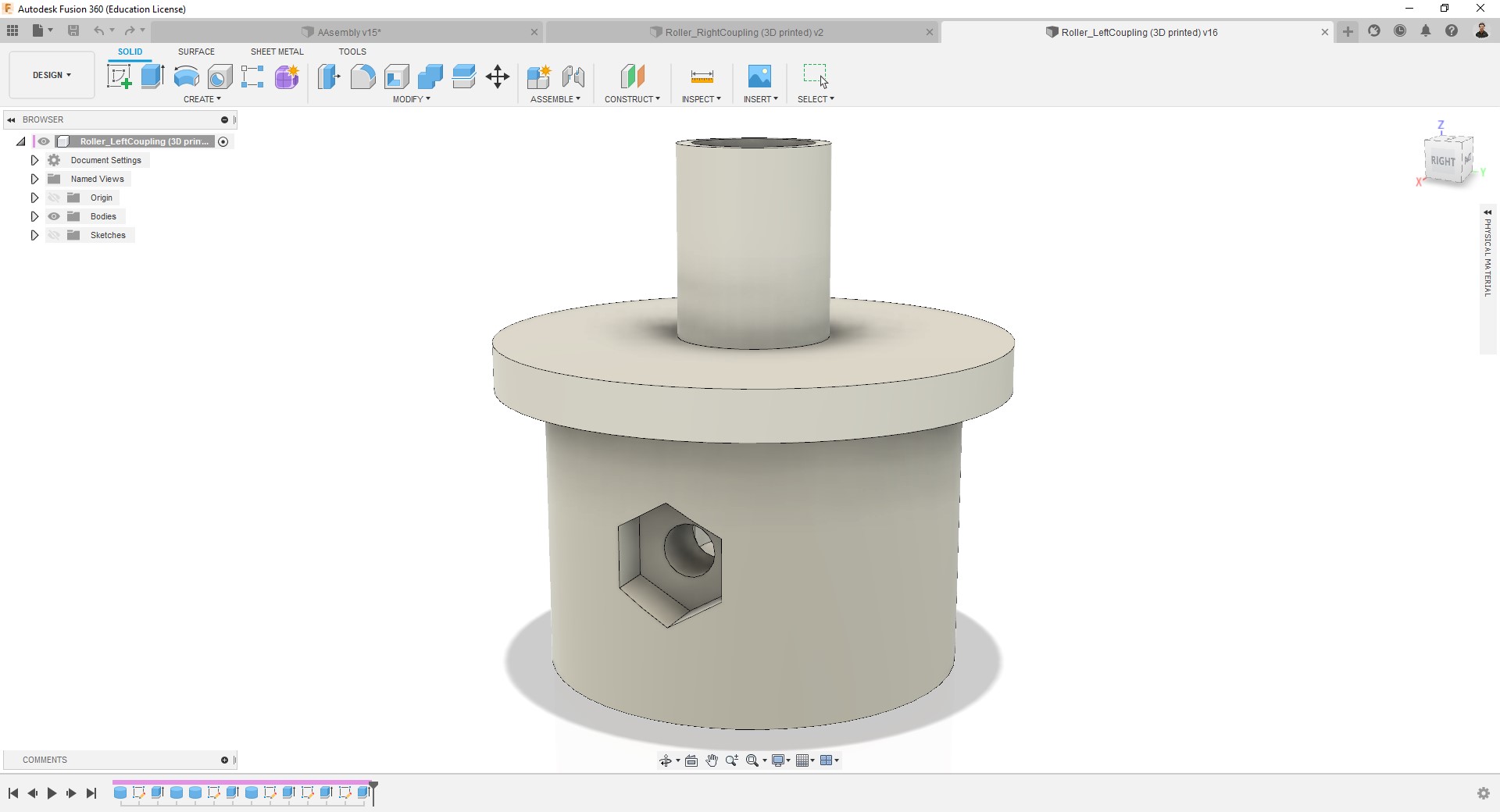
This model includes includes two pockets (one inside and another outside) to introduce M3 nuts, to adjust the motor shaft.
Roller and Cutting bed
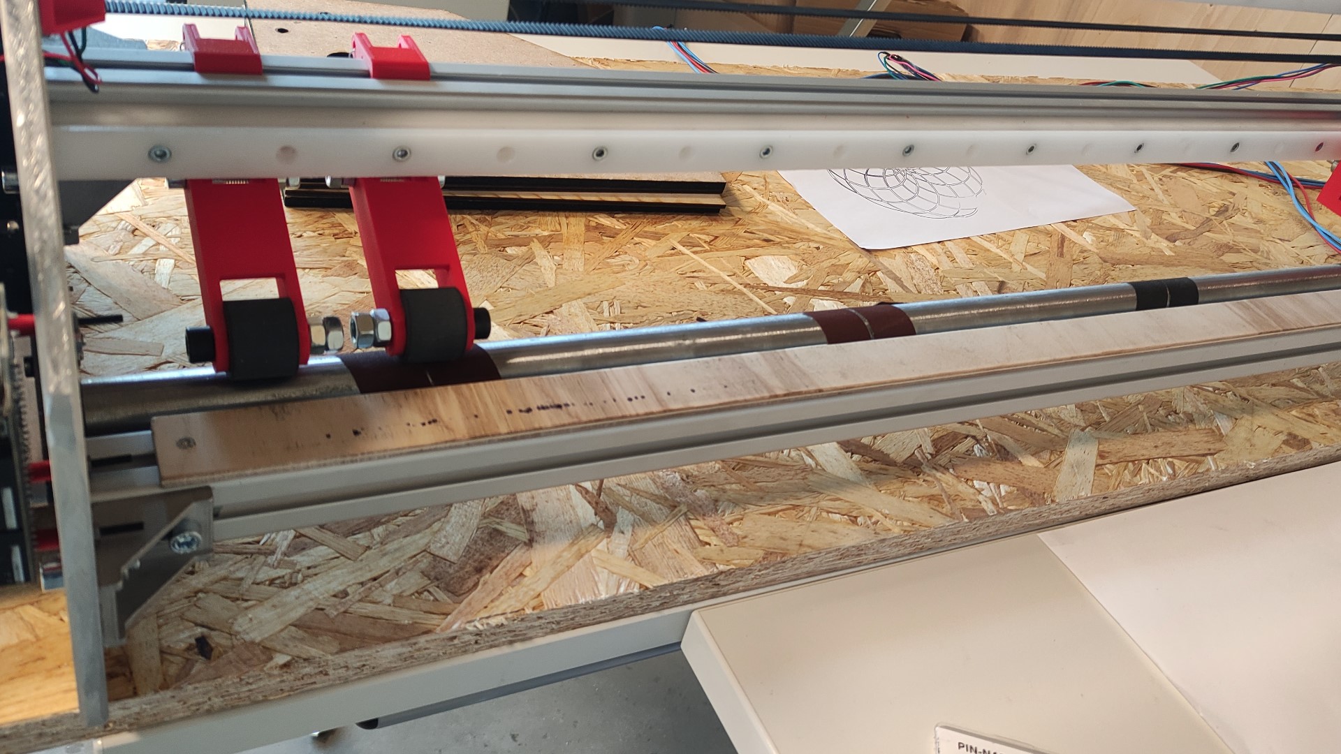
- I have cut and sanded a metallic pipe to use it as a roller for the Y axis.
- I have glued some sandpaper to the roller for creating friction against the vinyl/paper.
- A cutting bed of a material such as nylon was needed but since we were almost out of time, I improvised a wooden bed which I attached using my 3D printed T-nuts.
- I have also cut the aluminum profiles.
3D printing
-
Nema23 holder:
Print summary:
- 3D printer = Ultimaker S5.
- Filament = 2.85 generic black PLA.
- Nozzle = AA0.4
- Layer height = 0.2mm
- Wall = 1.2mm
- Infill = 50%, Lines.
- Support = Disabled.
- Build plate adhesion = None. -
T-nuts:
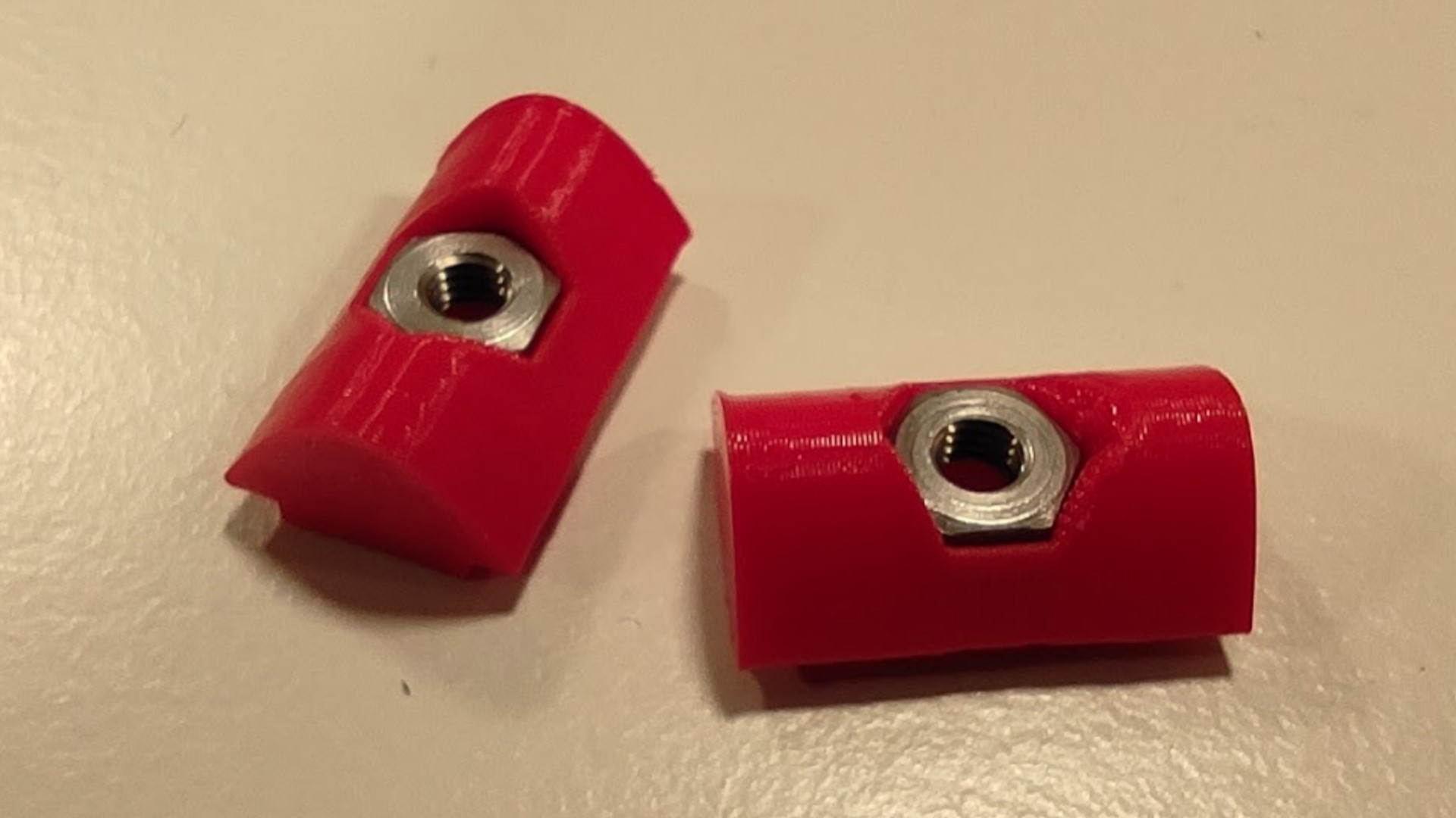
They resulted being stronger than I expected.
Print summary:
- 3D printer = Ultimaker S5.
- Filament = 2.85 generic red PLA.
- Nozzle = AA0.4
- Layer height = 0.2mm
- Wall = 0.8mm
- Infill = 100%, Grid.
- Support = Disabled.
- Build plate adhesion = Brim. -
Coupling:
- This is the printed part with the nuts.
- This is how it looks mounted on the machine. It’s probably not the best material for this application, but it worked! 😄
Print summary:
- 3D printer = Ultimaker S5.
- Filament = 2.85 generic black PLA.
- Nozzle = AA0.4
- Layer height = 0.2mm
- Wall = 1.2mm
- Infill = 50%, Grid.
- Support = Disabled.
- Build plate adhesion = None.
- This is the printed part with the nuts.
Computer controlled cutting
-
Before making the side supports with the official material (aluminum), I have made test pieces in MDF which I laser cut.
-
First goal was testing stability of the design:
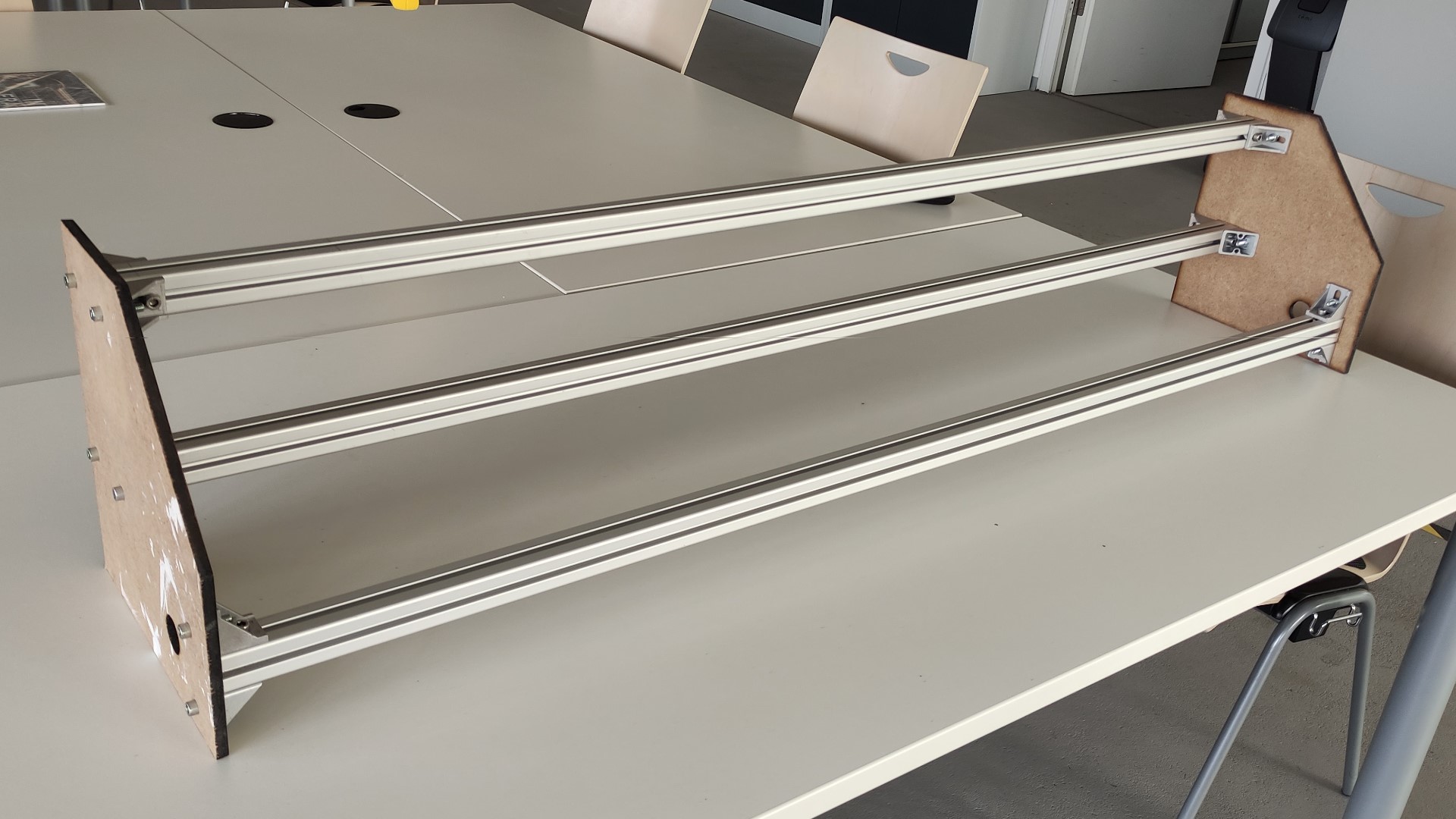
It was very stable, more than all of us expected. -
Secondly, these pieces serve to consider the necessary modifications:
After this I have added an extra space in the back for the electronics, made holes for the X axis belt, and moved some screw holes for the brackets.
Computer controlled machining
- I prepared the g-code with my instructor using the Manufacture workspace of Fusion 360:
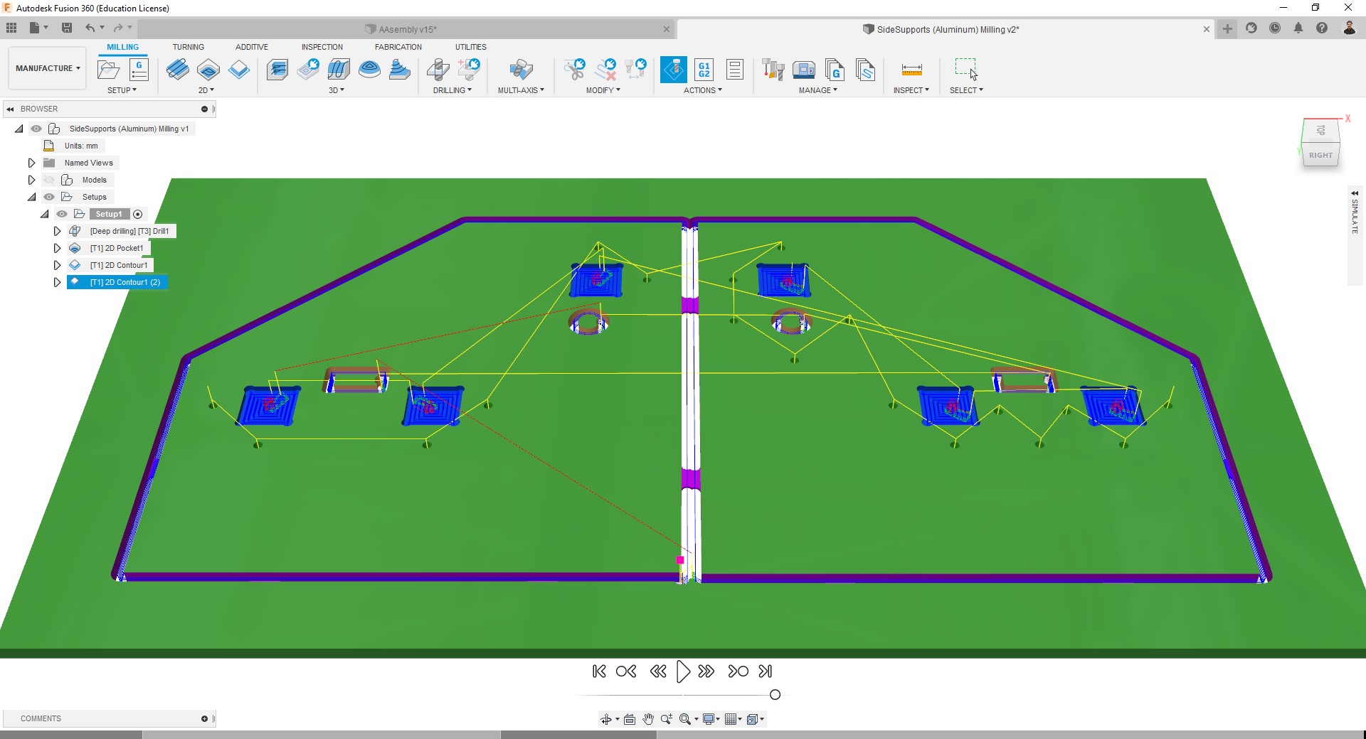
The toolpaths used for it were:
- Drilling - with a Ø5mm drilling tool.
- Pocket - with a Ø6mm milling tool.
- Contour - with a Ø6mm milling tool.
Since due to Corona-restrictions the access to the FabLab was almost impossible during these days, I have gone to Daniele Ingrassia’s Lab for milling.
- I milled it with my instructor and then I have sanded the pieces.
- On one of them we have mounted the motors and electronics:
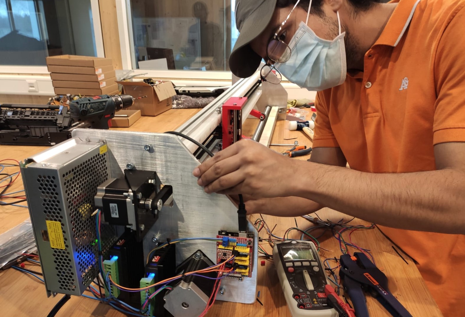
- While the other is rather freer:
- On one of them we have mounted the motors and electronics:
Machine performance
Finally, we used a marker to make a test of its behavior:
Test result:
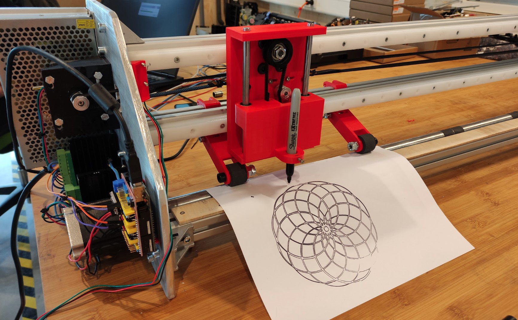
The small parts not drawn are because the bed is not completely flat, I have not managed to cut it evenly with the band saw. That’s also why we haven’t used the knifes and test it with vinyl.
Outlook:
- Even when the goal is making a Vinyl cutter, at this point (testing it with a marker) it works perfectly fine as a plotter machine.
- We already have the knives for cutting (also the Z axis mechanism was already designed to use the knives), but current the not-uniform bed could lead them to damage and also wood is not the best material for it.
- Later we’ll change the bed and use the knives to make the machine cut vinyl.
Files
- Nema23Holder.stl
- T-nut.stl for 30x30 aluminum profiles.
- Fusion 3D model: VinylCutter.f3z.
- Fusion project link.