6. 3D Scanning and printing
- Test the design rules for your printer(s). Document your work and explain what are the limits of your printer(s) (in a group or individually):
Group assignment page: here.
My individual part: I have documented it in the Test piece part of the 3D print process section.
- Design and 3D print an object (small, few cm3, limited by printer time) that could not be easily made subtractively:
I experimented a bit with OpenScad, to see how a 3D object can be modeled with code.
The models that I have printed, due to their shapes, are not possible to be made substractively with the common 3-axis machines, but can be made with a 5-axis CNC (which are rather much more expensive).
- The 3D printer I used was Ultimaker S5, with a AA0.4 and BB0.4 nozzle.
- For slicing I used Cura.
- The materials I used for printing were PLA for model and PVA for supports.
- 3D scan an object, try to prepare it for printing (and optionally print it):
Since I already had some experience on 3D printing, I was very excited for the 3D scanning part of this assignment.
I practiced Photogrammetry and Structure light for 3D scanning and I have 3D printed my scans.
Photogrammetry:
- Photos were taken with an smartphone.
- The 3D reconstruction software I used was Meshroom.
- For post-processing I used Blender.
Structured light:
- 3D scanner I used was the EinScan Pro+.
- The software I used was the EinScan.
3D scan
Photogrammetry | Me
Is a technique that overlaps photos of an object, structure, or person, and convert them into a 3D model.
So for it I decided to scan… Me! 😀
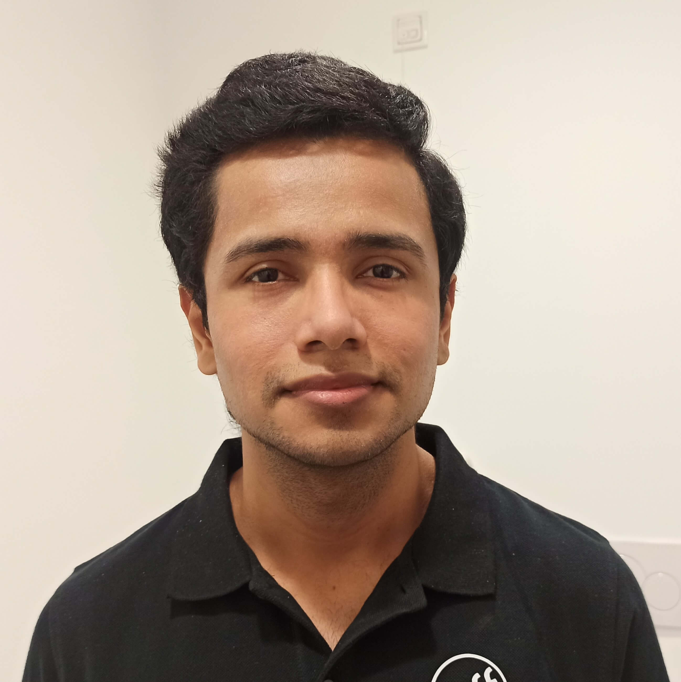
Preparation
This part consists on th considerations you need to take for getting nice results:
-
Make sure you’ll have the same amount of light during taking the photos, then for it is the artificial light is preferred.
-
If having any item/part that produces shadow on the object, use extra lights to illuminate the dark areas, or it can result o=in a “hole” on the model.
-
When having relatively big areas with no features, using marks is highly recommended so the software uses them as references to the overlapping:
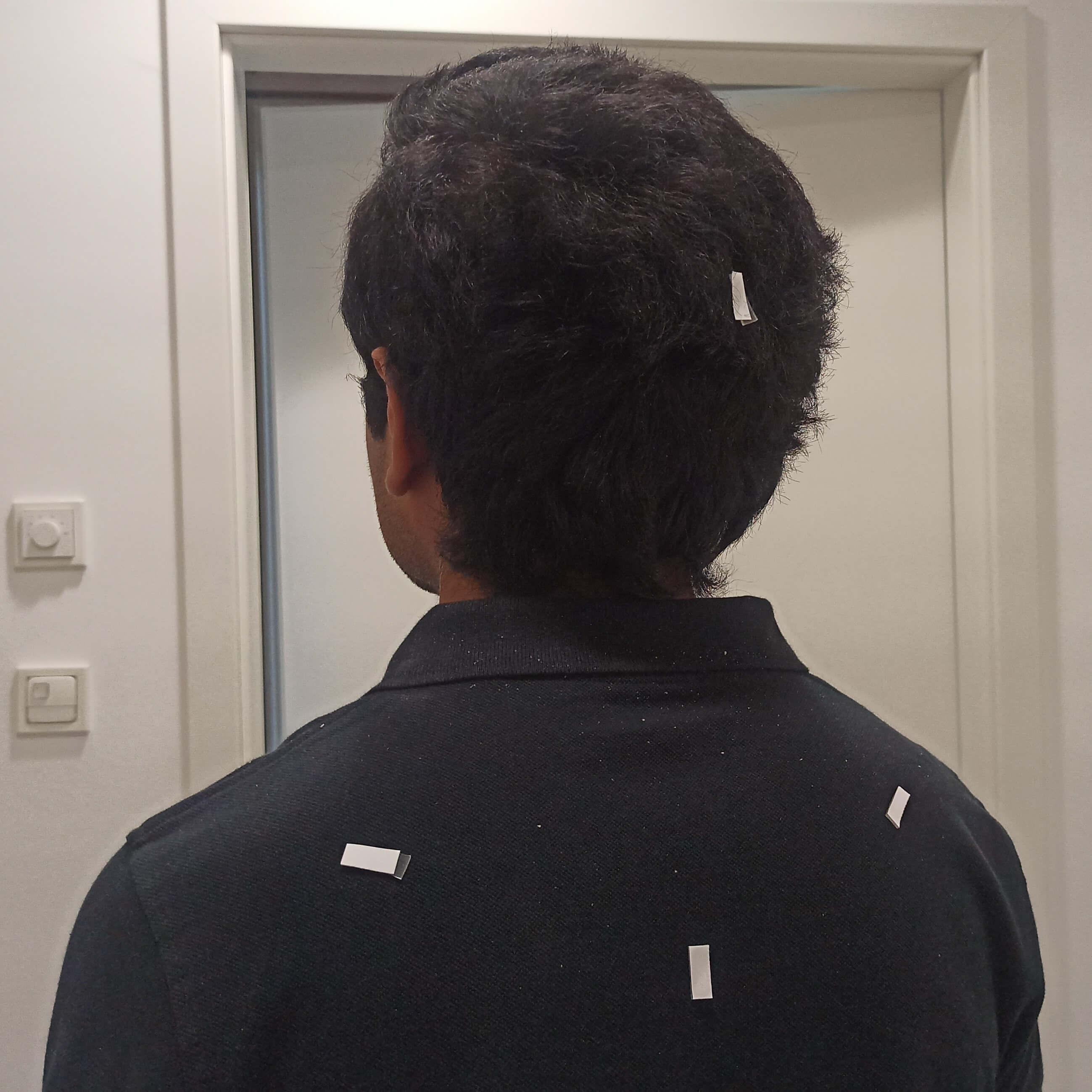
-
Now you just need to start taking photos of all of the possible views (in this case, my colleague took 115 photos of mine).
-
Important! The person/object to scan shouldn’t change the pose.
3D recons. software | Meshroom
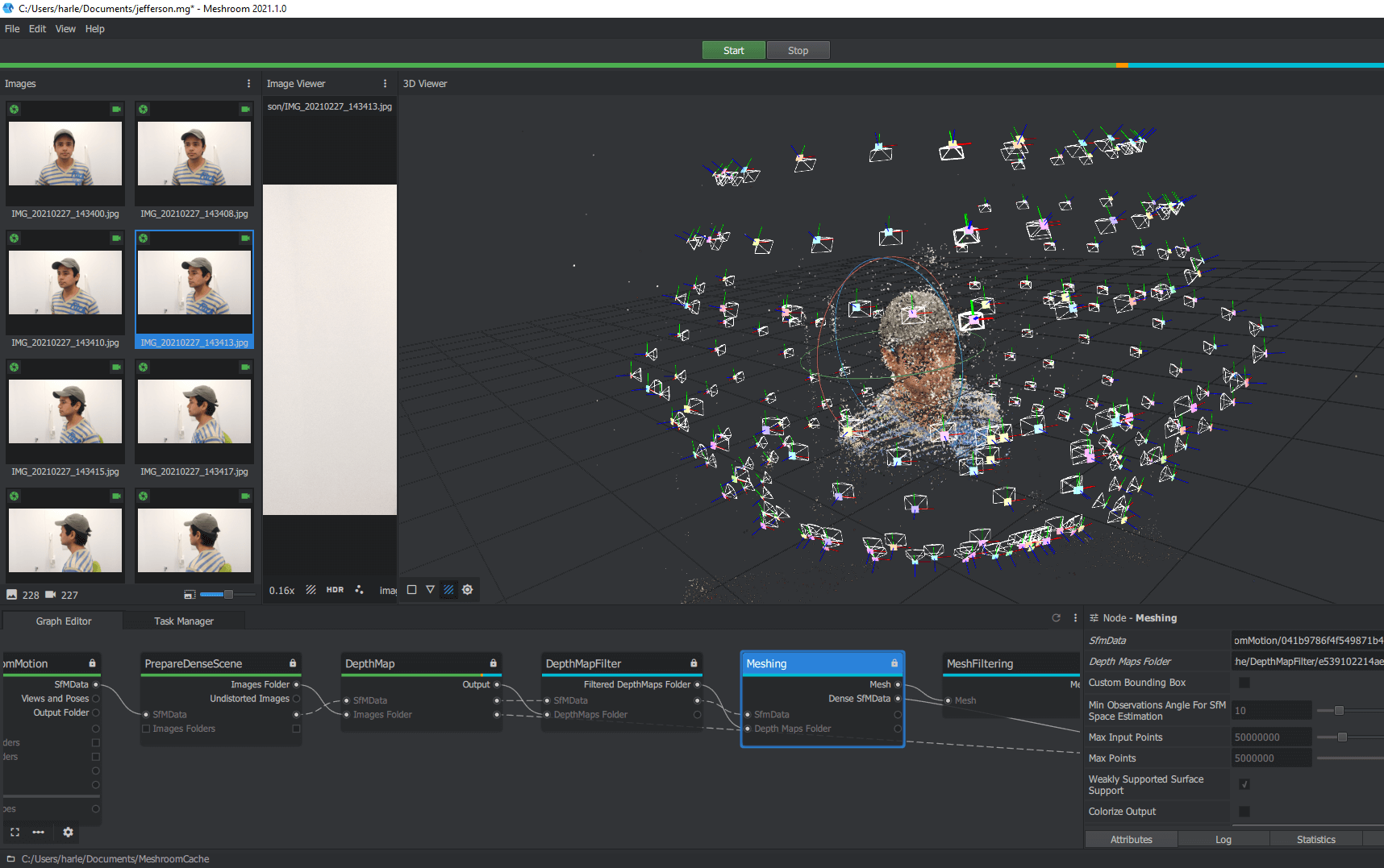
-
Once you have all of the photos, remove the bad ones (if there are), put it on a folder and drop it to Meshroom.
-
Press Start and let it make its magic.
-
Once it’s finished, it’s ready to be post-processed, just save your files.
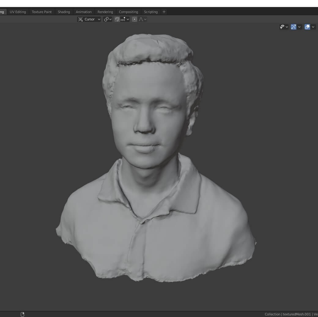
Post-process | Blender
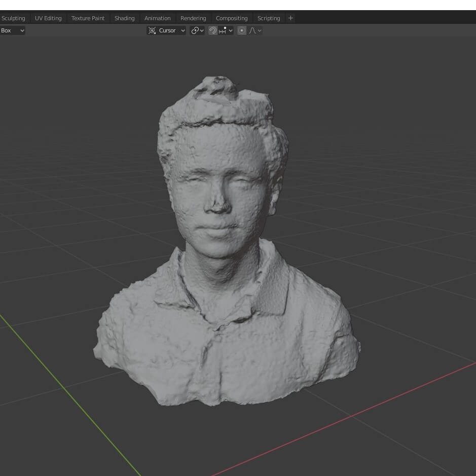
-
Open the file.... and start tuning!
I’m not really experienced in Blender, but I got the basic explanation of the commands I needed with a colleague.
I have done it in the Sculpt Mode, using mainly the commands: Draw, Draw sharp, Smooth, and Flatten.
-
Use the texture (color) that already comes from Meshroom.
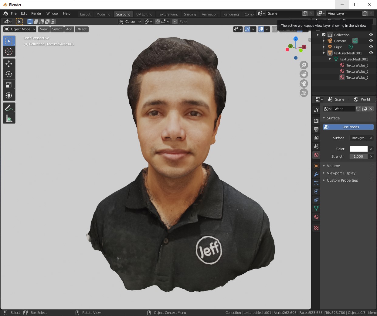
-
I Played with the lights and made a Render:
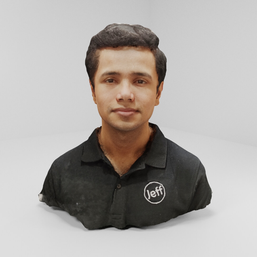
…yes, it scared me that the model looks more like me than myself.
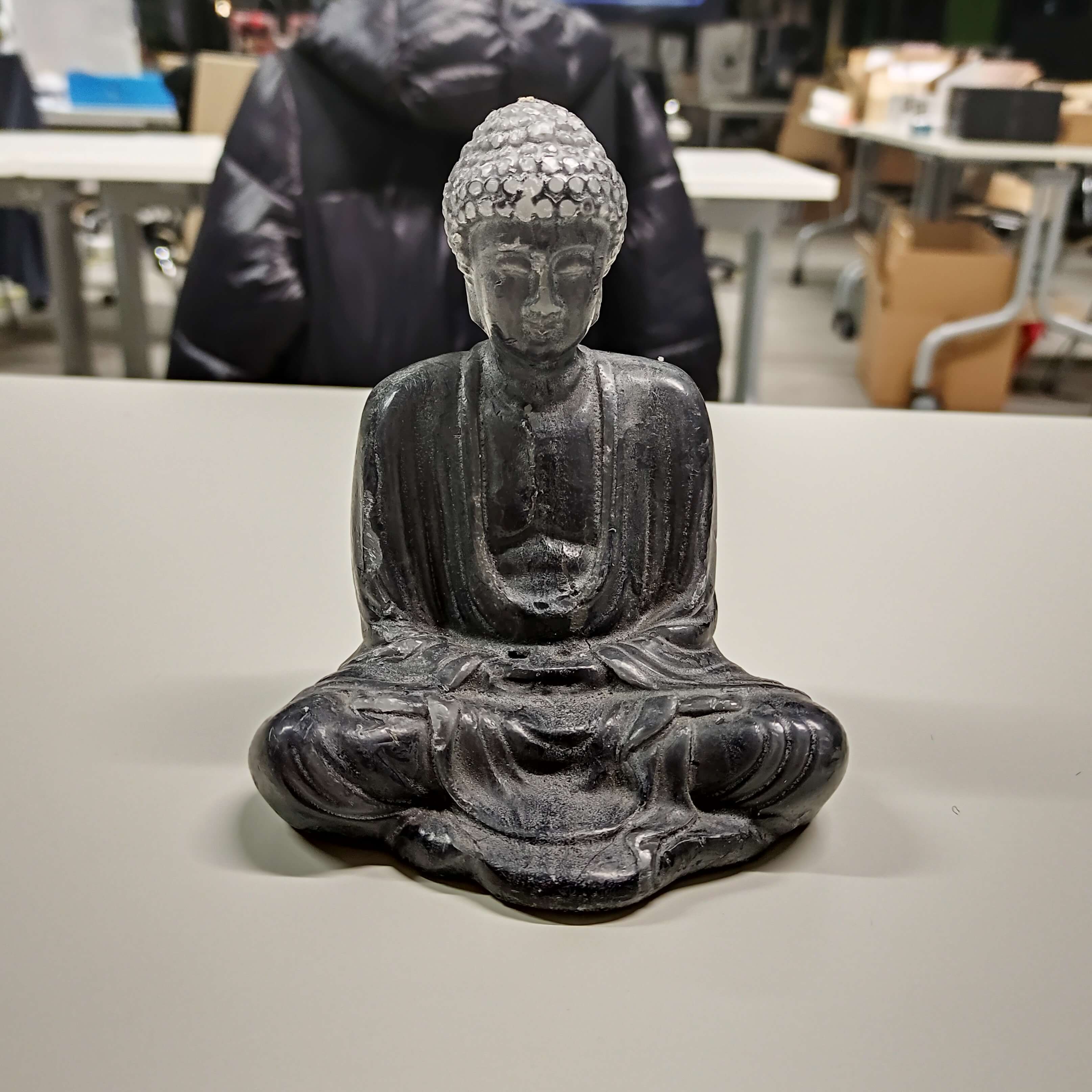
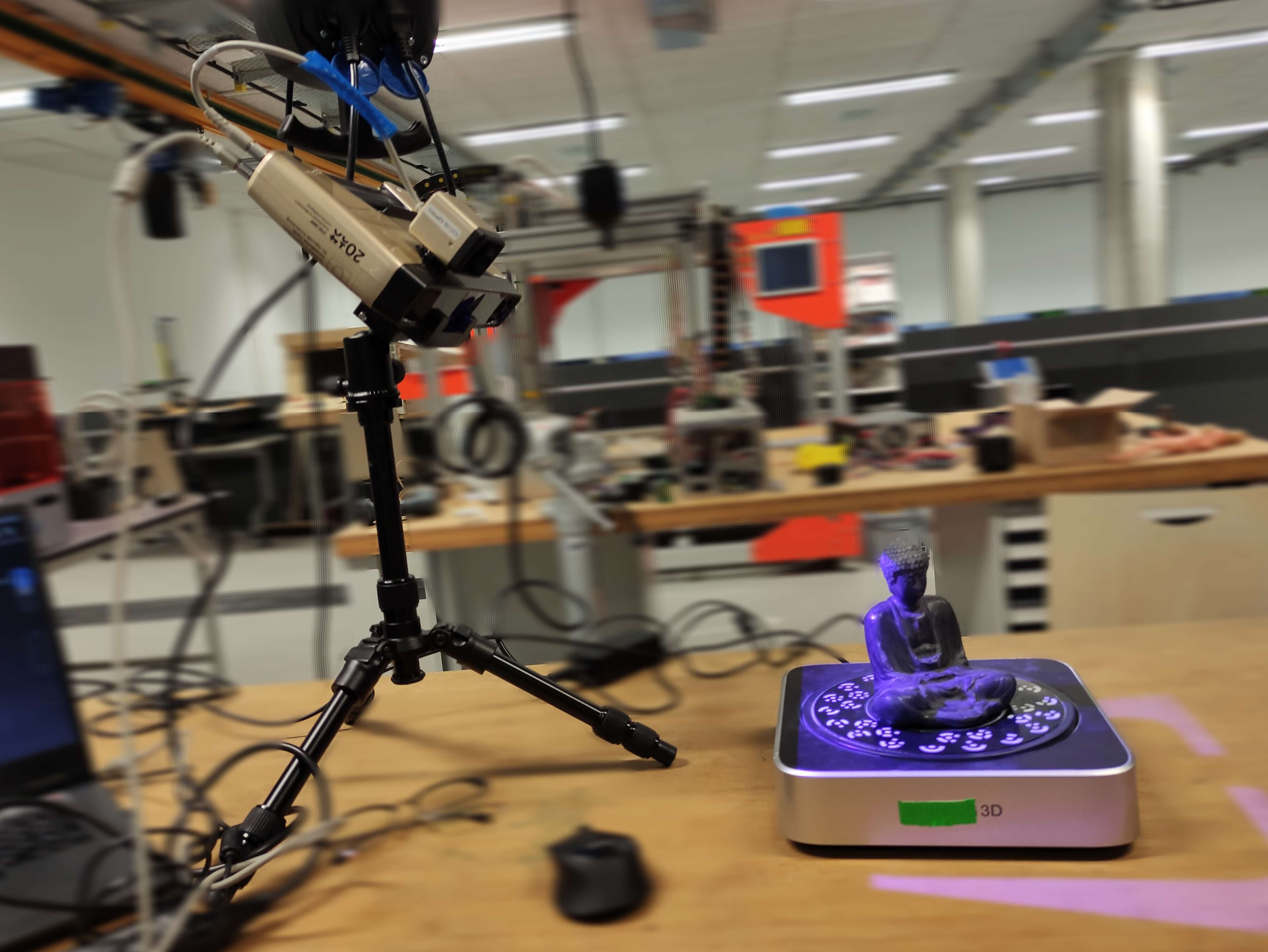
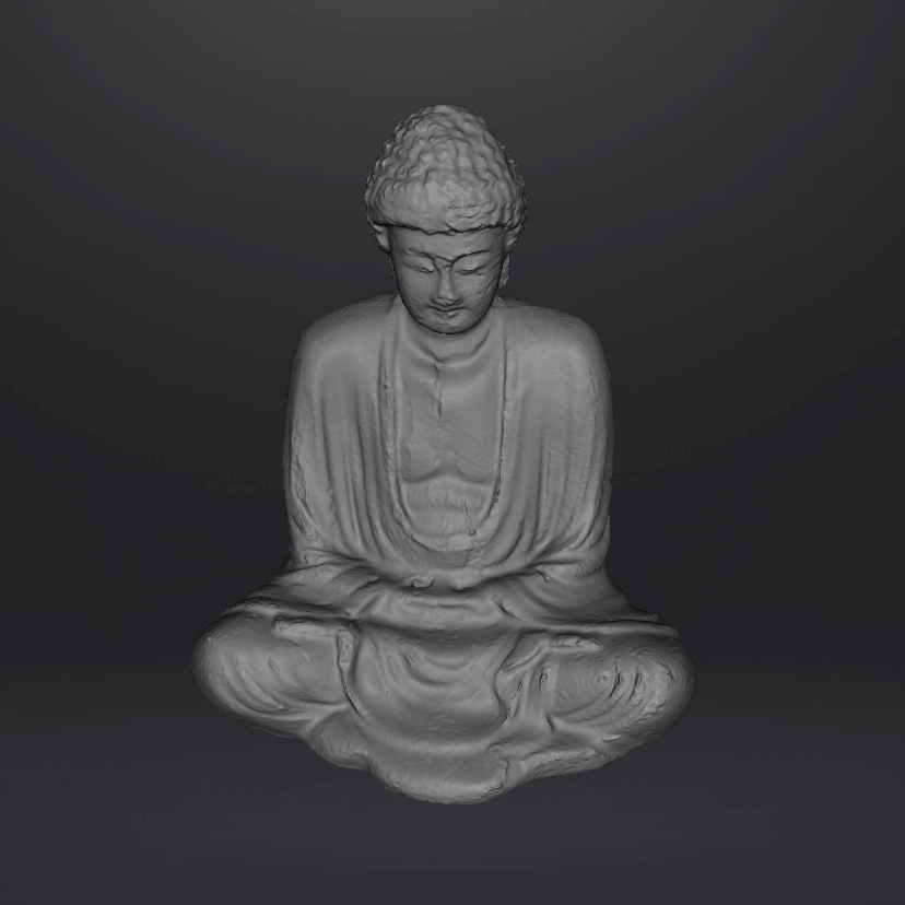
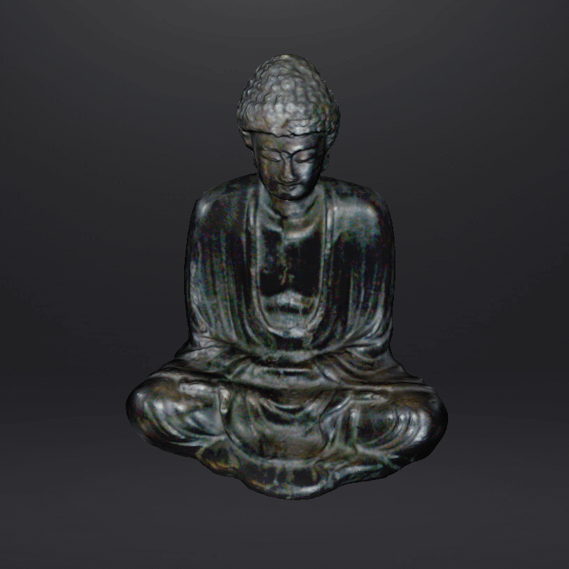
Structured light | Buddha
Is a technic that displays a pattern on the surface of an object and senses it with a camera to analyze the shape of the object according to the deformation of the pattern.
This time I went for an object, so I decided to scan this candle of Buddha:
Preparation
This part consists on th considerations you need to take for getting nice results:
-
Make sure you’ll have the same amount of light during taking the photos, then for it is the artificial light is preferred.
-
If having any item/part that produces shadow on the object, use extra lights to illuminate the dark areas, or it can result o=in a “hole” on the model.
-
When having relatively big areas with no features, using marks is highly recommended so the software uses them as references.
-
Important! The person/object to scan shouldn’t change the pose.
Scanning | EinScan Pro+
This scanner has different functions to scan different sizes, in this case I used Fixed Scan.
- Use different brightness of the light and different positions of the object.
3D recons. software | Meshroom
The software literally guides you through the whole calibration and scanning process, then just try it yourself.
3D print | Fused Filament Fabrication
3D printing, or additive manufacturing, is the construction of a three-dimensional object from a digital 3D model.
The First of all, existing additive technologies are also worth briefly mentioning:
| Type | Technologies |
|---|---|
| Extrusion | Fused filament fabrication (FFF) |
| Light polymerized | Stereolithography (SLA) Digital Light Processing (DLP) |
| Powder bed | Powder bed and inkjet head (3DP) Electron-beam melting (EBM) Selective laser melting (SLM) Selective heat sintering (SHS) Selective laser sintering (SLS) Direct metal laser sintering (DMLS) |
| Laminated | Laminated object manufacturing |
| Powder fed | Directed Energy Deposition |
| Wire | Electron beam freeform fabrication (EBF) |
The technology I applied for this assignment [and the most popular all over the world] was Fused filament fabrication (FFF).
Fused filament fabrication (FFF), also known as Fused Deposition Modeling (FDM) is a 3D printing process that uses a continuous filament of a thermoplastic material.
Filament is fed from a large spool through a moving, heated printer extruder head, and is deposited on the growing work.
The print head is moved under computer control to define the printed shape. Usually the head moves in two dimensions to deposit one horizontal layer at a time; the job of the print bed is then to move vertically a certain distance to start a new layer.
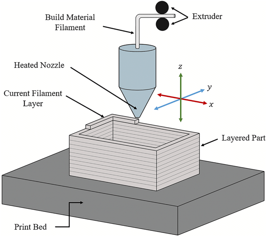
image: Basic working principle of material extrusion printing (Shah, et al., 2019).
image taken from 3D Printing Today
Parameters
Before starting with the process, we have a look on the parameters (which are configured in the Slicer).
There are a lot of parameters to customize our printings, but the main ones we need to know are:
Layer height
It’s the exact height of each layer of material extruded, given in mm. Affects the final printing resolution.
* When working with pieces that are basically vertical extrusions such as cylinders and cubes (or any piece that in general doesn’t need good vertical resolution), then thicker walls are OK.
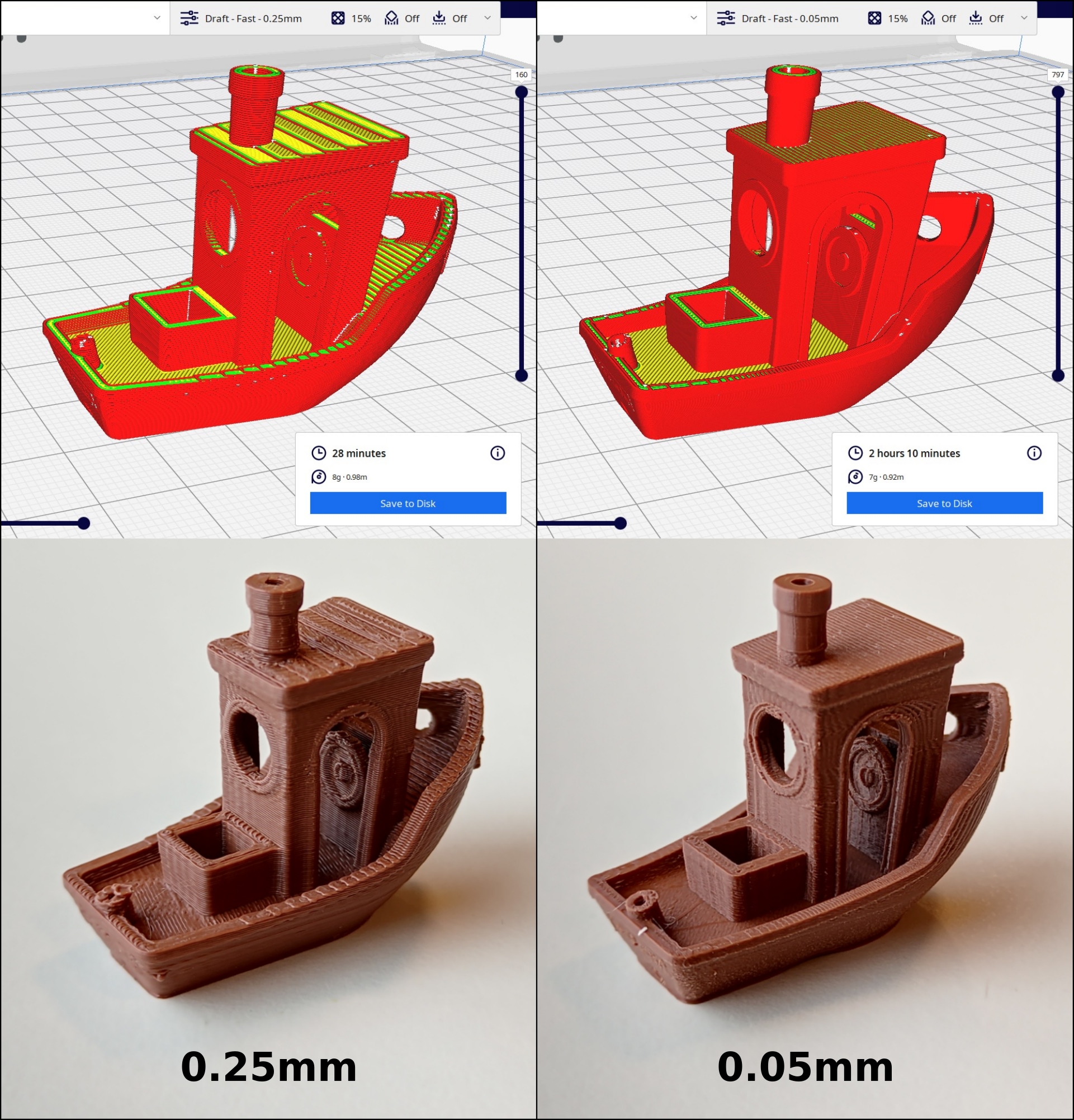
model used: 3DBenchy
To consider:
- Thinner layer = longer printing time.
- Thicker layer = shorter printing time.
Wall thickness
Refers to the thickness of the external layer of the piece, given in mm or in amount of lines. Affects the final strength of the piece.
* When working with didactic or testing pieces, decoration (or any piece that doesn’t need to be strong), then thinner shells are OK.
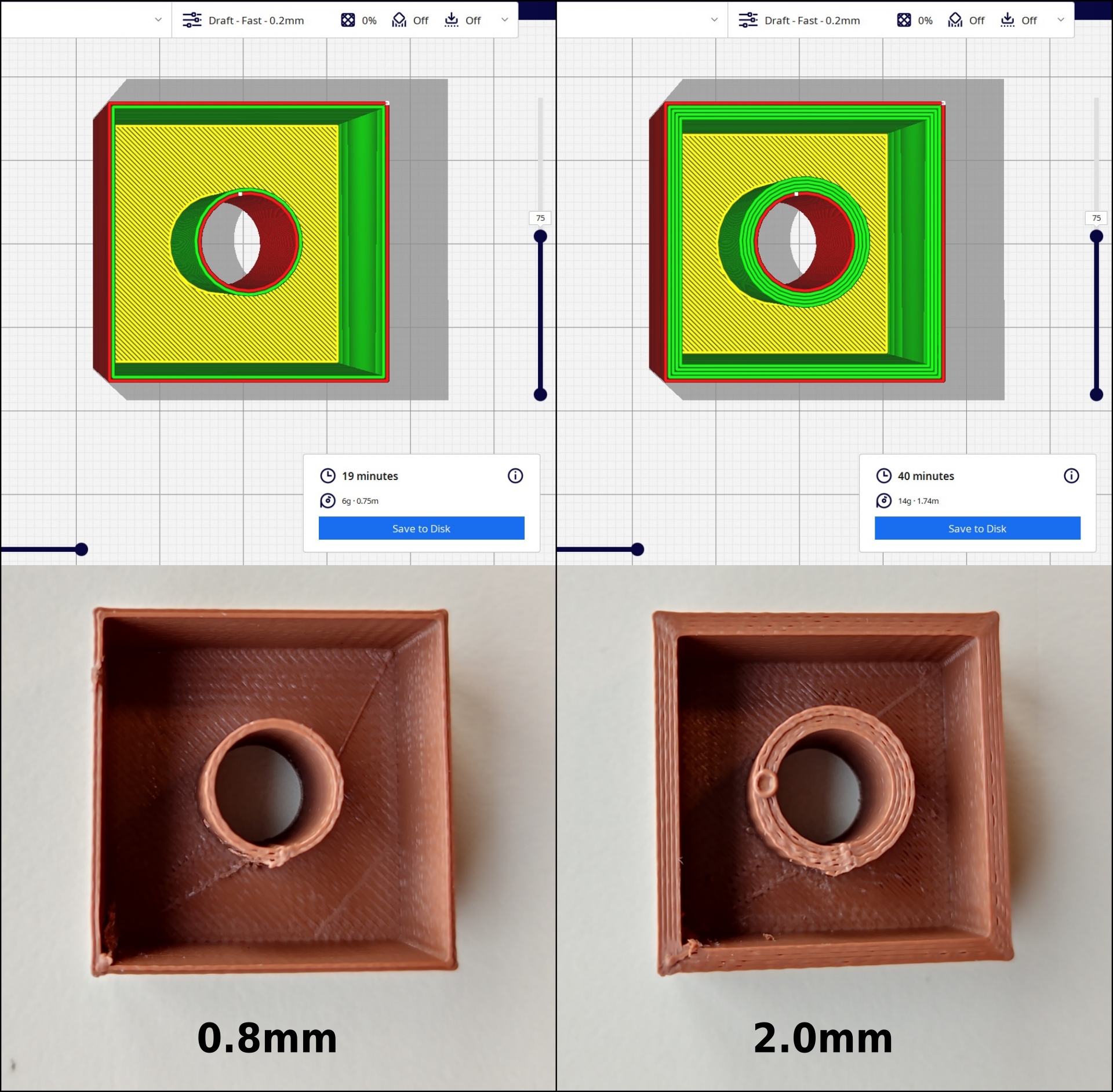
To consider:
- Thinner shells = shorter printing time.
- Thicker shells = longer printing time.
Infill
Refers to how solid is internally the piece going to be, is given in percentage. Affects the final strength of the piece.
* When working with didactic pieces, tests, decoration (or in general doesn’t need to be strong), then lower infill percentages are OK.
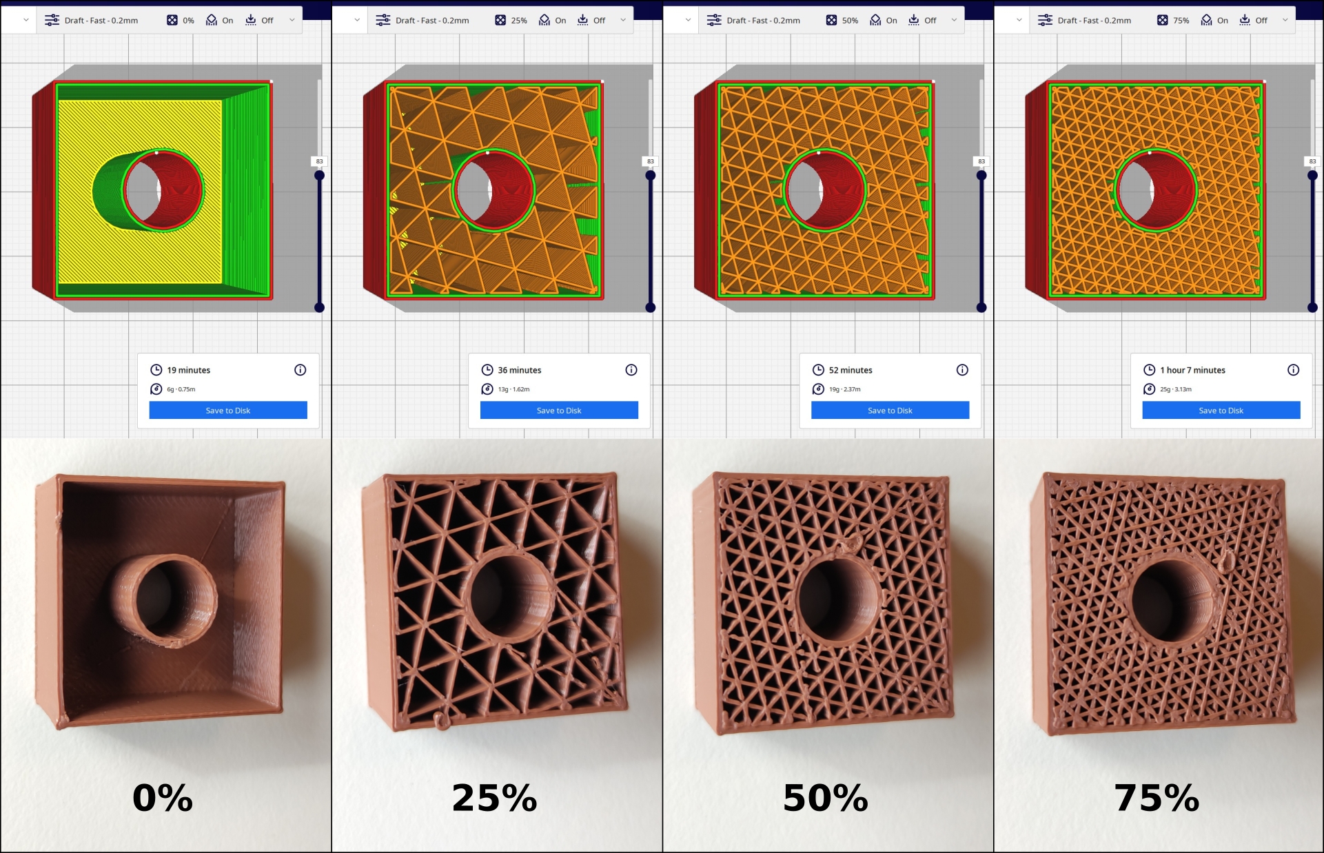
infill pattern used: Triangle
To consider:
- Lower infill = shorter printing time.
- Higher infill = longer printing time.
Plate adhesion
Different options that help to improve both priming the extrusion and adhesion to the build plate.
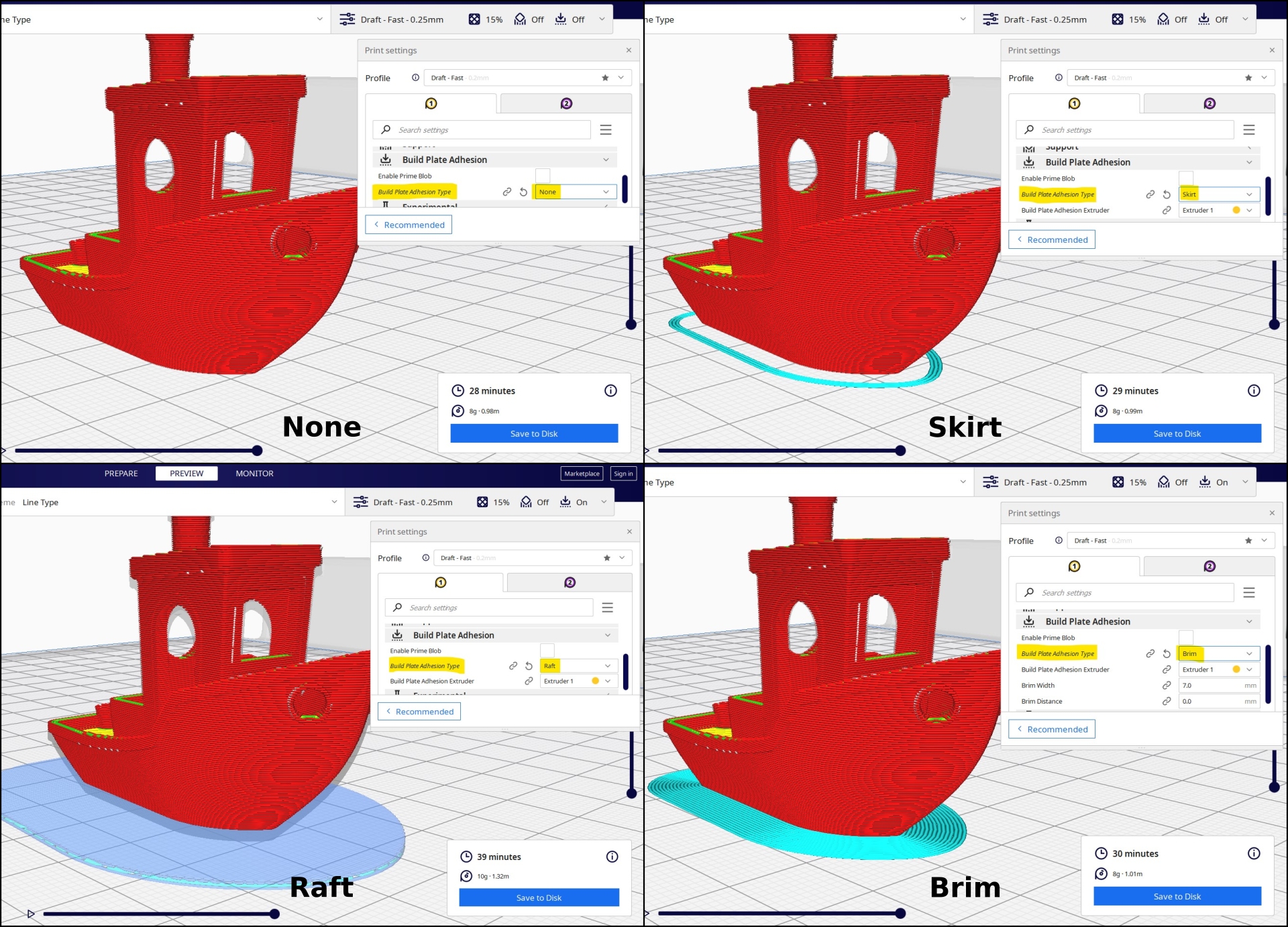
* Raft: adds a thick grid with a roof below the model. It is primarily used with ABS to help with warping and bed adhesion, but they can also be used to help stabilize models with small foundations.
* Brim: adds a single layer flat area around the base of the model to prevent warping. It is often used to hold down the edges of the model, which can prevent warping and help with bed adhesion.
To consider: This constructions have almost none effect on printing time.
Support
Is a structure used when the model has an overhang.
An overhang in 3D printing occurs when the filament extruded by the nozzle “hangs” from the previous layer too far, to a point where it’s in the air and cannot be held properly. This results in the extruded layer “sticking out” and producing poor print quality as it cannot form a good base underneath… or a completely failed print. 😬
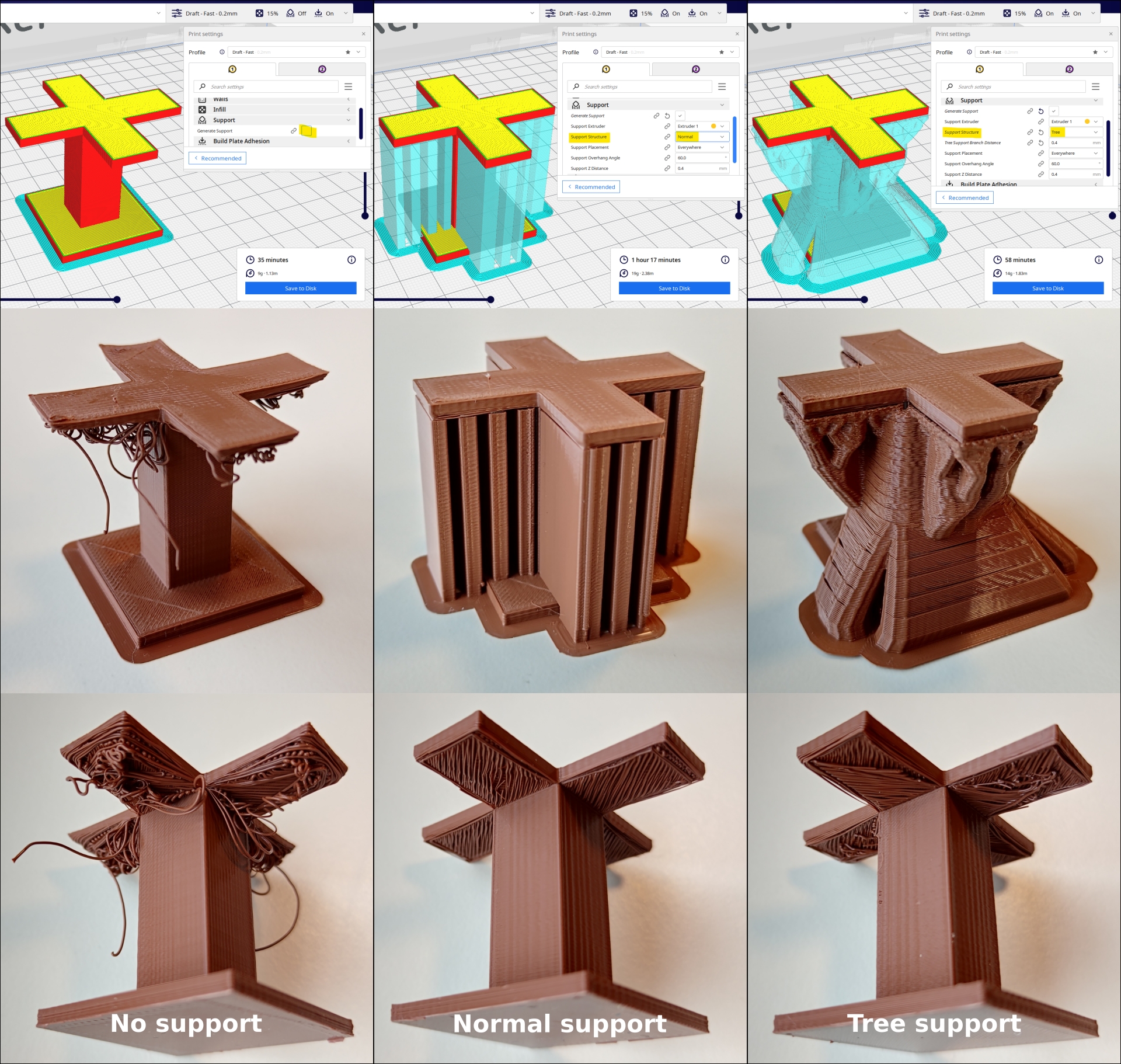
model used: Customizable 3D printer support test
* Tree support: creates branches towards the overhanging areas that support the model on the tips of those branches, and allows the branches to crawl around the model to support it from the built plate as much as possible.
To consider: The effect over time will depend on the type of support used as well as the area supported. It’s preferred to print the piece in an orientation that needs less supports.
Process
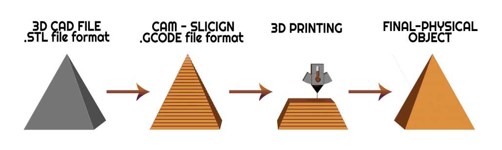
image taken from My3Dconcepts
3D CAD model
The most commonly used file format is STL, however there are other formats such as OBJ, and 3MF. We can find further information with the pros and cons of each one in All3DP.
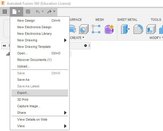
Exporting our models:
Using Fusion 360 as example, the steps would be:
-
File > Export…
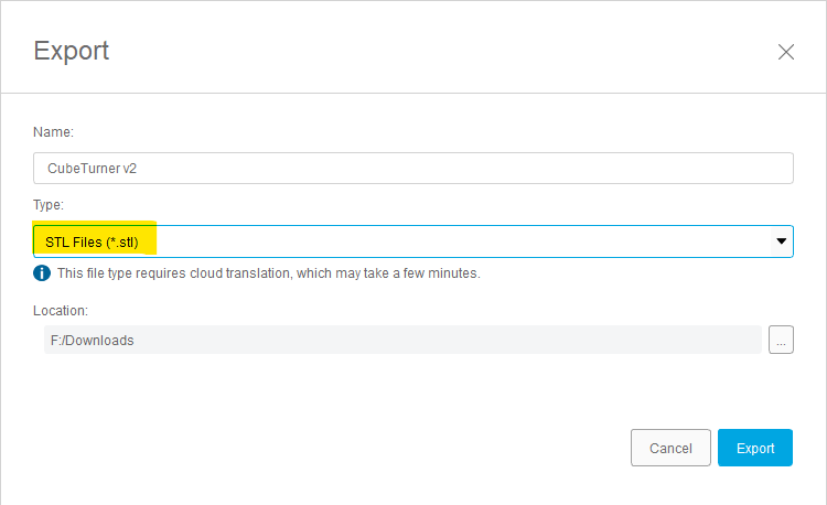
-
Select STL files (or one alternative for 3D printing) and Export:
Downloading free models
We can also some free 3D models (including pieces for testing, didactic pieces, etc.) in these pages:
- Thingiverse
- Sketchfab
- TraceParts
- GrabCAD
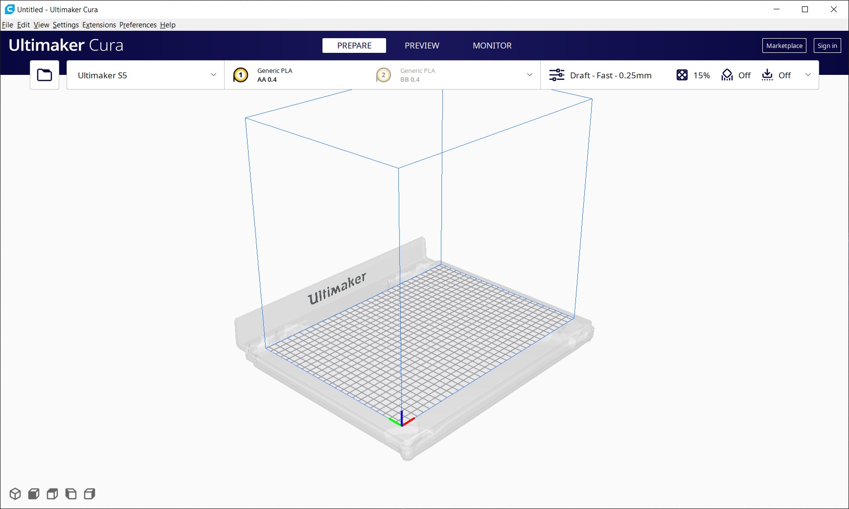
Slicer | Ultimaker Cura
Slicer, also known as “slicing software” is used for the conversion from a model in STL format to printer commands in g-code format which tells the printer motors where to move, how fast, and what path to follow.
I used Ultimaker Cura v4.11.0.
Structure and settings:
-
The Prepare tab allow us to quickly setup our printing:
-
Top Left:
- Open file:
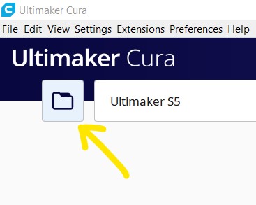
- Open file:
-
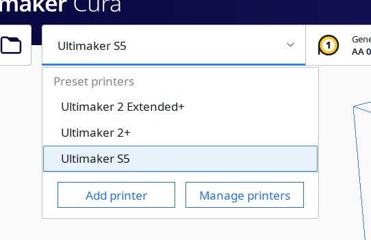
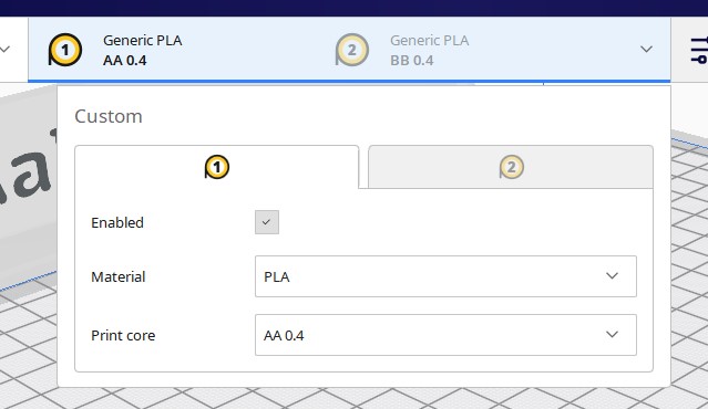
Top:
- Printer: Ultimaker S5
- Material and Print core: Generic PLA, AA 0.4
- Print settings (also known as parameters):
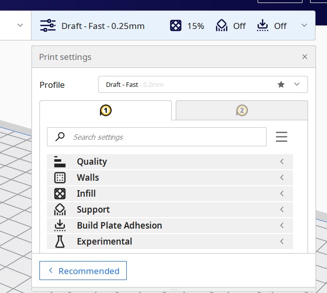
- Printer: Ultimaker S5
-
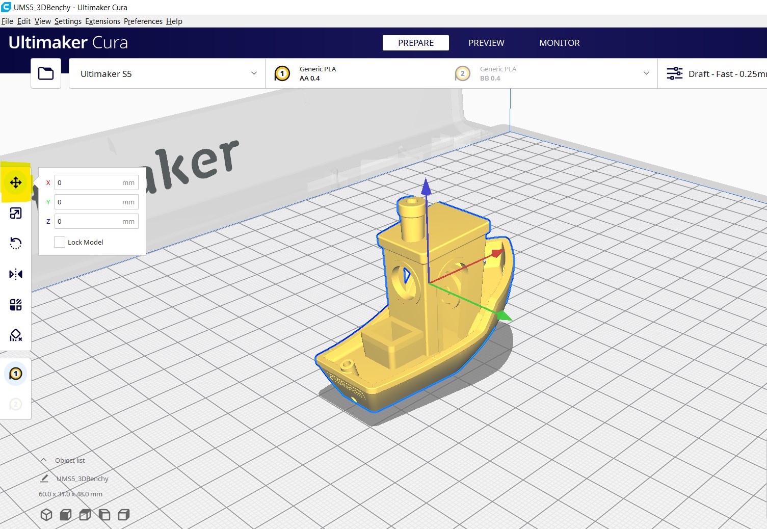
Left, the most important are:
- Move model:
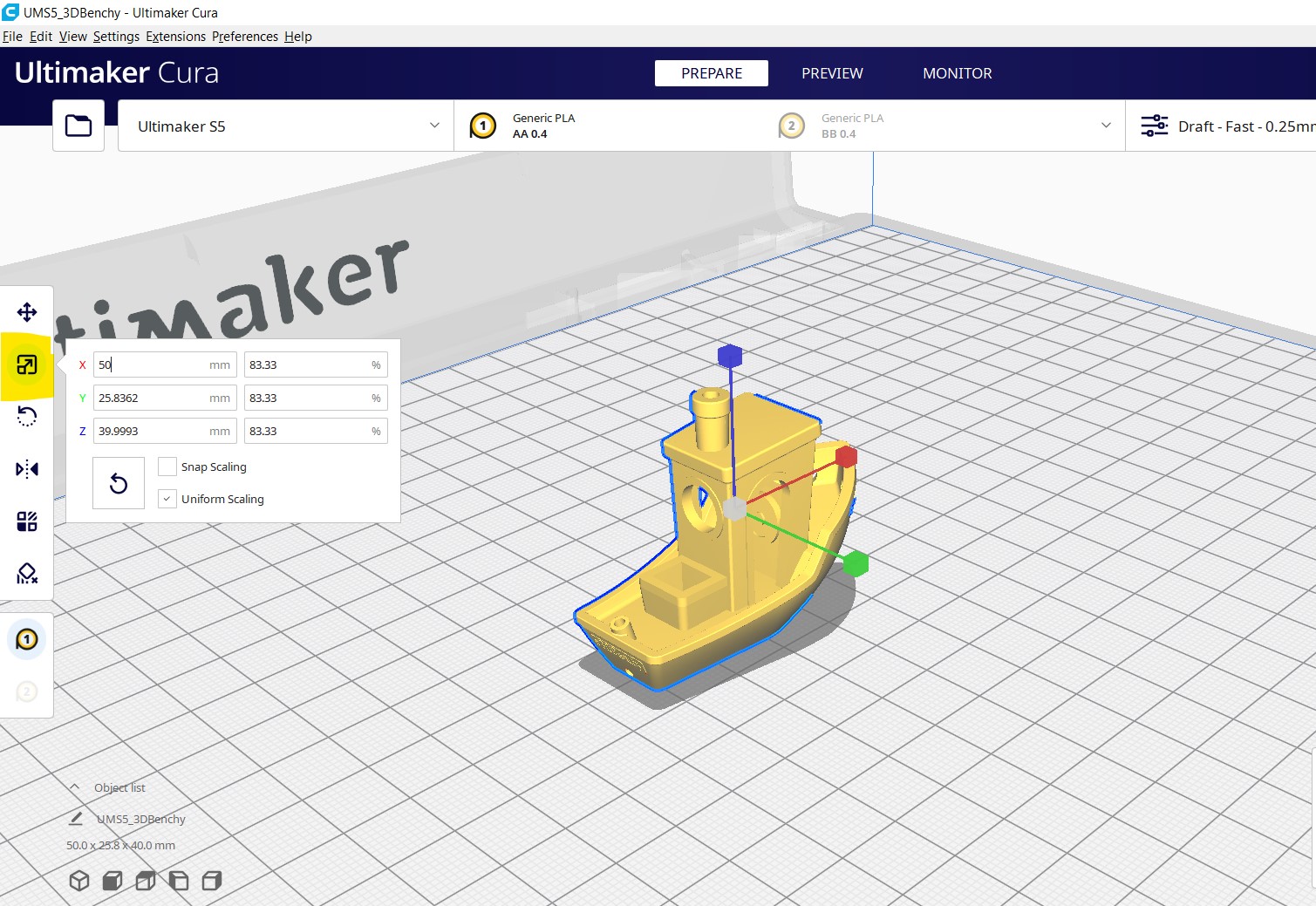
- Scale model:
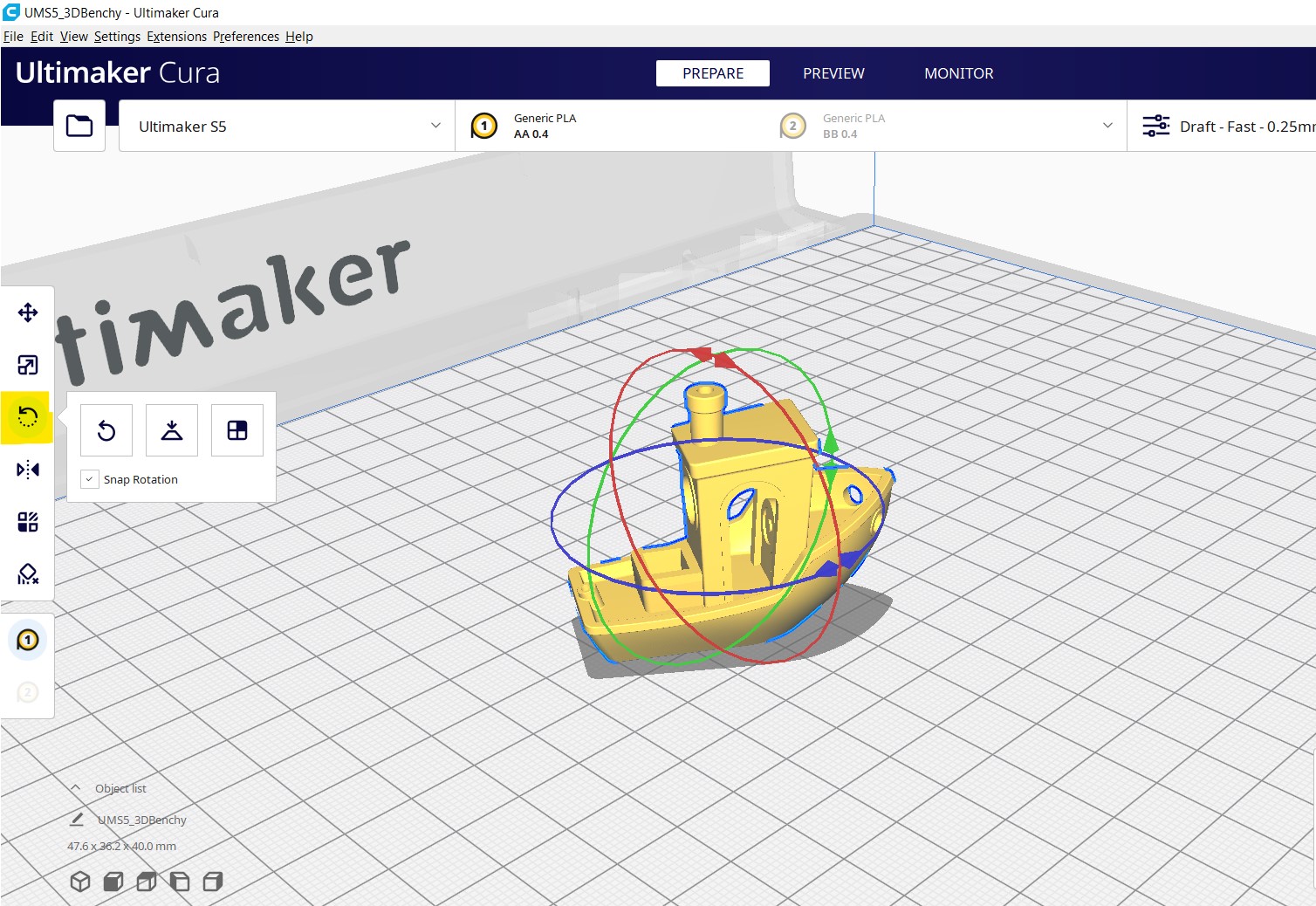
- Rotate model:
- Move model:
-
Bottom left:
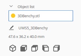
- List of models.
- Printing file name.
- Printing volume.
- Model views.
-
Bottom right:
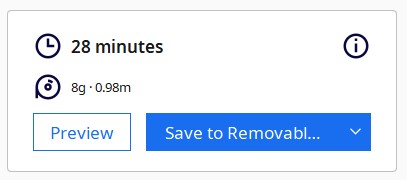
- Printing time.
- Material: weight and filament length for this print.
- Preview and Save file.
-
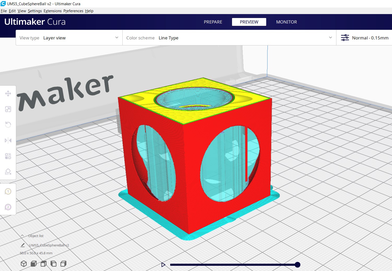
-
The Preview tab allows us to watch the printing layer by layer, check the supports, infill and plate adhesion structure:
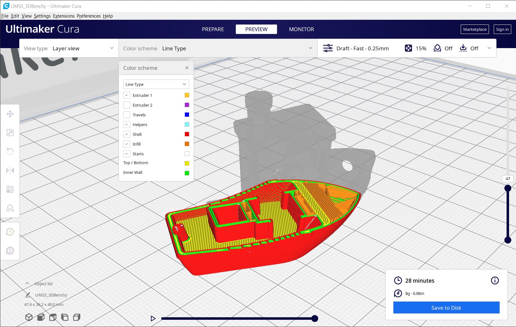
- Top: Color scheme.
- Right: Layer bar.
- Bottom: Simulate process of current layer.
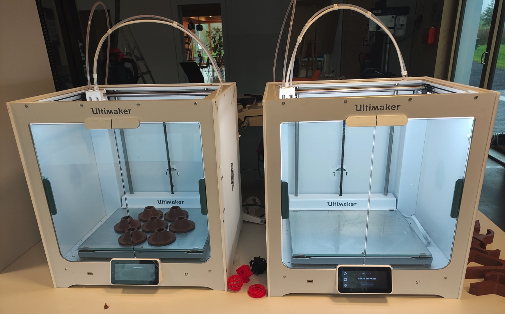
3D printer | Ultimaker S5
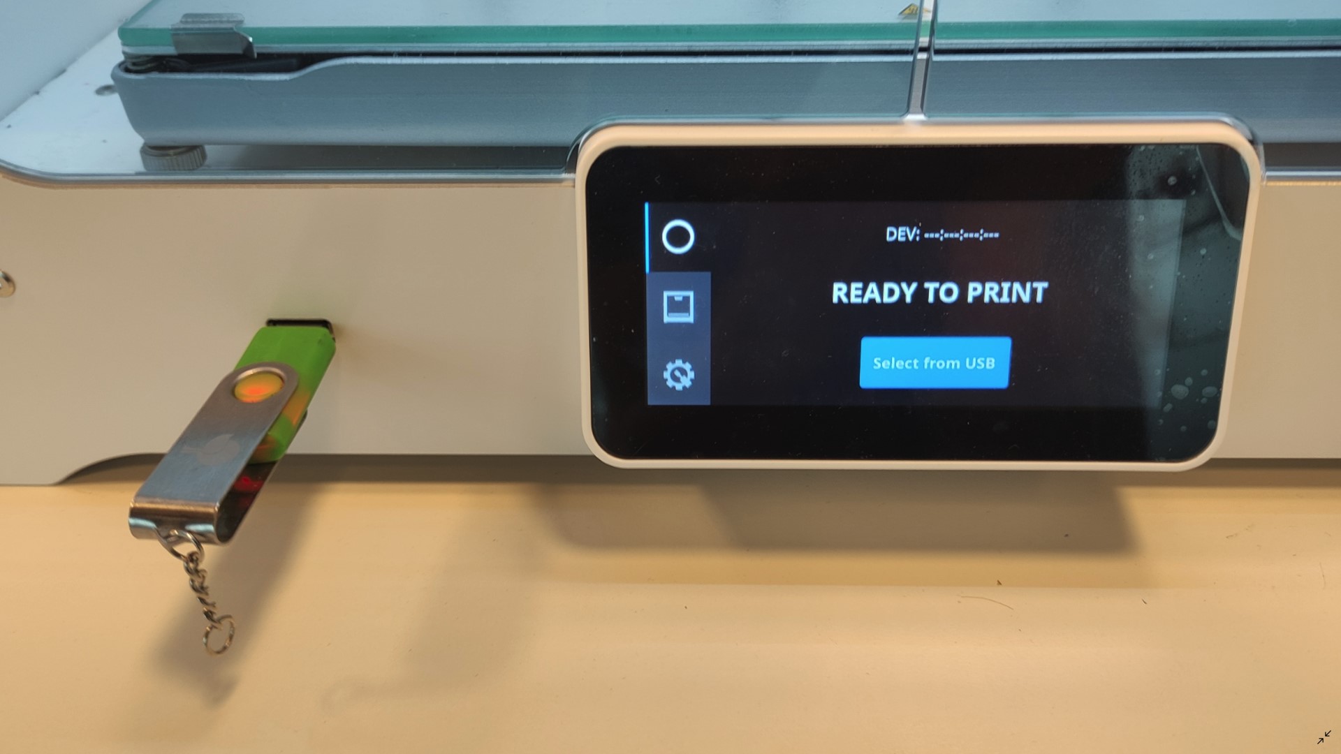
The 3D printer I used was Ultimaker S5, with a AA0.4 and BB0.4 nozzle.
-
Insert USB stick (other models use SD cards), and press Select from USB:
-
Select file to print.
Now the printer starts preparing to print. During this time (about 5mins in this printer model) it heats up the plate and nozzles, and calibrates the level of the plate:
-
It starts printing:
-
Remove your piece and press Confirm removal:
Note: The ease of removing the piece depends on the width of its base (first layer, which includes the brim) and if substances have been used to improve adhesion. A tool like a spatula will help.
Tip: A cooler plate makes the removing easier. After the print finishes wait a couple of minutes for the plate to cool down and then remove your piece.
Post process
- Remove the Adhesion and Support constructions if any. Using tools like pointed pliers, slotted screwdrivers, also a knife will make it easier.
- If a very smooth and nice result is desired, we can apply an epoxy resin coat. In some cases also sanding is needed.
Test piece 1
The recommendation for every fabrication technique is making a testing piece beforehand, in this case we want to know the “design rules for our printer”.
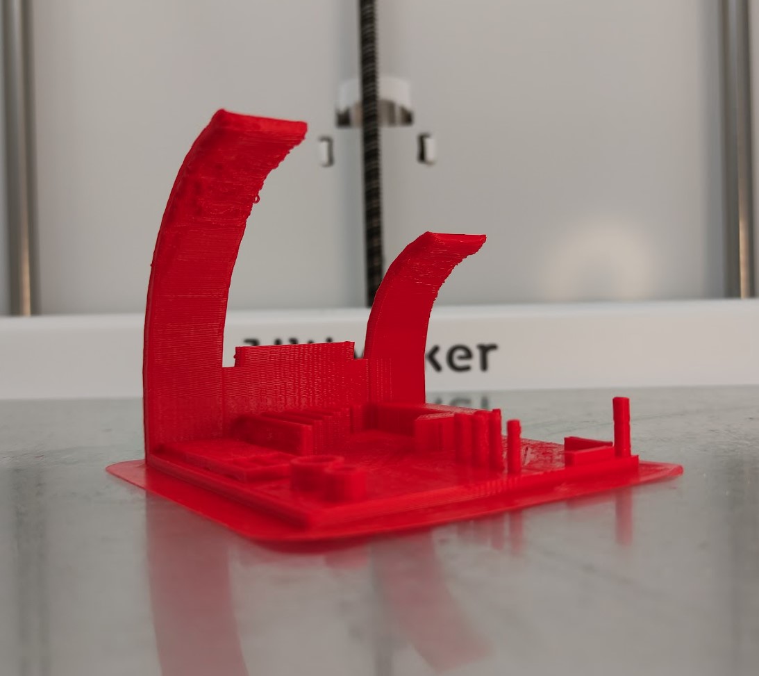
For this task I have used the All In One 3D printer test model by Marián Trpkoš that includes Overhang, Bridging, Hole and Diameter tests:
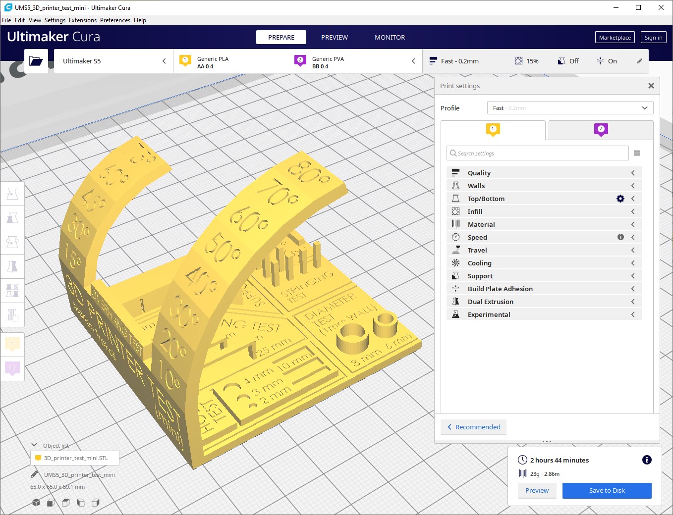
I used the default parameters of the Fast printing profile:
- Supports = Disabled
- Layer height = 0.2mm
- Build plate adhesion = Brim
- Infill = Triangles, 15%
- Infill speed = 70mm/s
- Wall speed = 55mm/s
Resulting piece:
The 3D printer I used during this assignment was the Ultimaker S5, with a AA0.4 (0.4mm) nozzle and 2.85mm generic PLA filament:
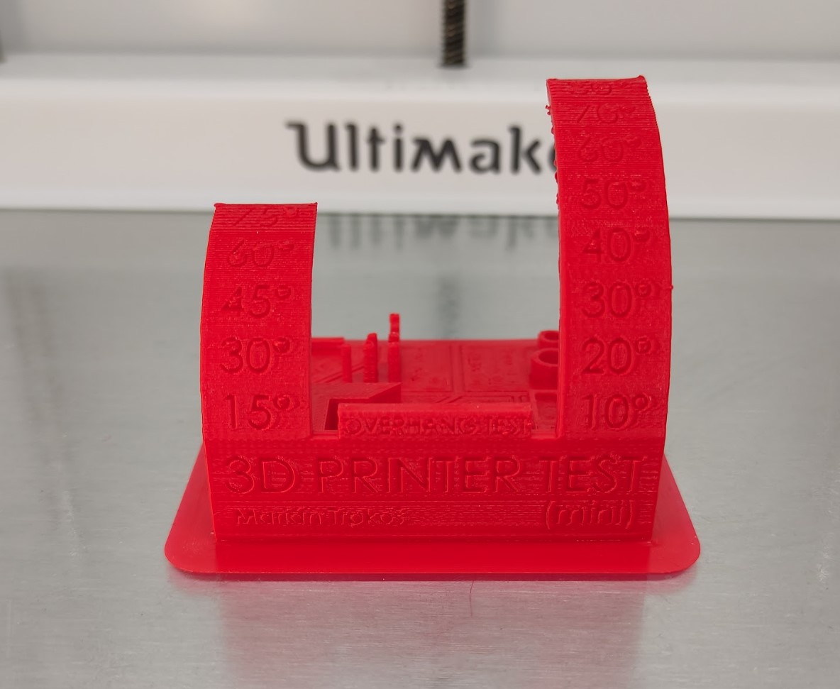
Conclusions:
From this piece we can take note of various aspects for both model design and slicer parameters; some of them are known at first glance, others have to be measured. The most important that I can mention are:
-
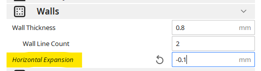
Printing tolerance = 0.25mm, it means that the printed walls of the piece are 0.25mm wider than the ones in the 3D model, . It can be fixed either editing the crucial measurements in the 3D model or simply using a negative Horizontal expansion in Cura:
-
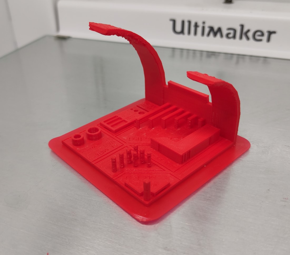
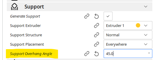
The minimum angle of overhang for which add support ≈ 45°:
-
The longest bridge that can be printed without starting to collapse = 20mm.
-
It was remarkable that horizontal text at this size doesn’t work that well 😅, it wasn’t readable.
-
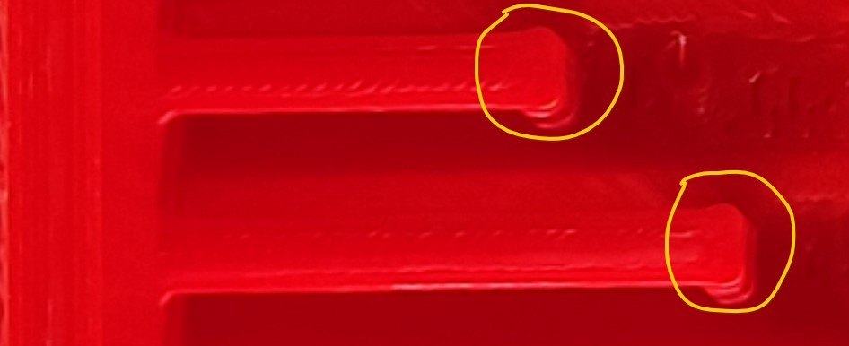
Sharp vertical positive edges are practically impossible to get, the printer in an attempt to complete the form, will add extra material. A recommendation for it would be to fillet the edges of the 3D model to at least the radius of the nozzle:
In general terms, the parameters of the printing profile used work fairly well if we want to print a first test/prototype/draft.
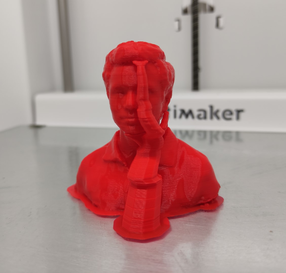
Mini Jeff
Model: 3D scanned using Photogrammetry.
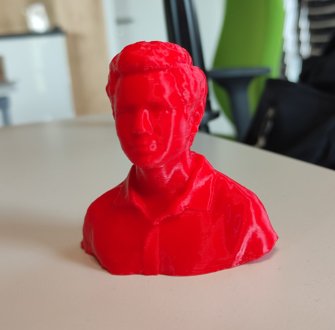
Printing details:
- Material = 2.85 mm generic PLA
- Model height = 70mm
- Layer height = 0.1mm
- Infill = Triangles, 20%
- Support = Enabled, type tree in PLA
- Plate adhesion = Enabled, in PLA
Buddha
Model: 3D scanned using Structured light.
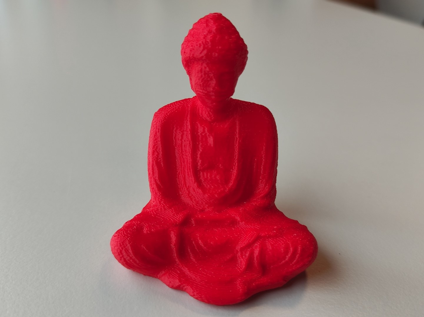
Printing details:
- Material = 2.85 mm generic PLA
- Model height = 65mm
- Layer height = 0.2mm
- Infill = Triangles, 20%
- Support = Disabled
- Plate adhesion = Enabled, in PLA
Turner cube
Model: made in Fusion 360
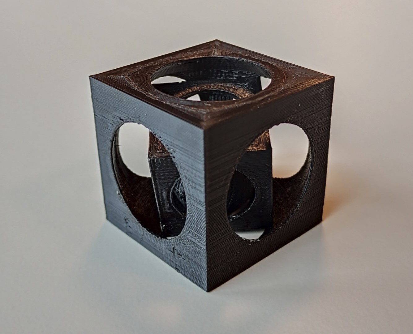
Printing details:
- Material = 2.85 mm generic PLA
- Model height = 45mm
- Layer height = 0.2mm
- Infill = Triangles, 20%
- Support = Enabled, in PVA
- Plate adhesion = Enabled, in PVA
Sierpiński triangle
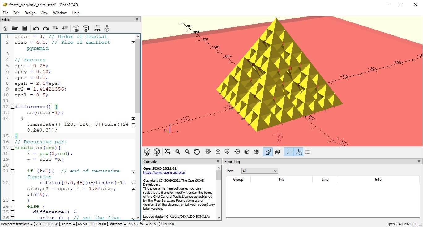
Model: made trying a code in OpenSCAD
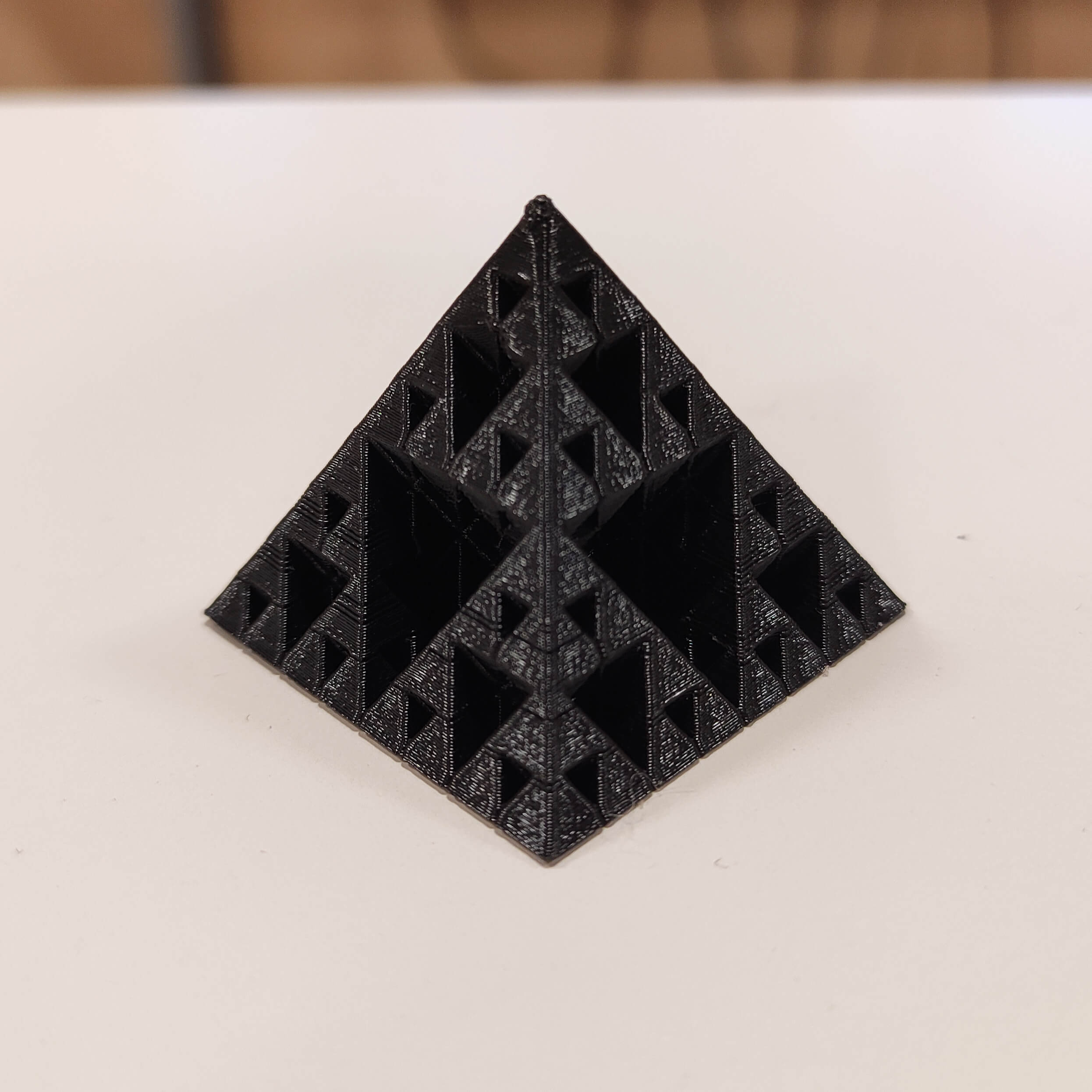
Printing details:
- Material = 2.85 mm generic PLA
- Model height = 30mm
- Layer height = 0.15mm
- Infill = Triangles, 20%
- Support = Enabled, in PVA
- Plate adhesion = Enabled, in PVA
Assignment outlook
Even when I already have experience on 3D printing before, I have experimented new things:
-
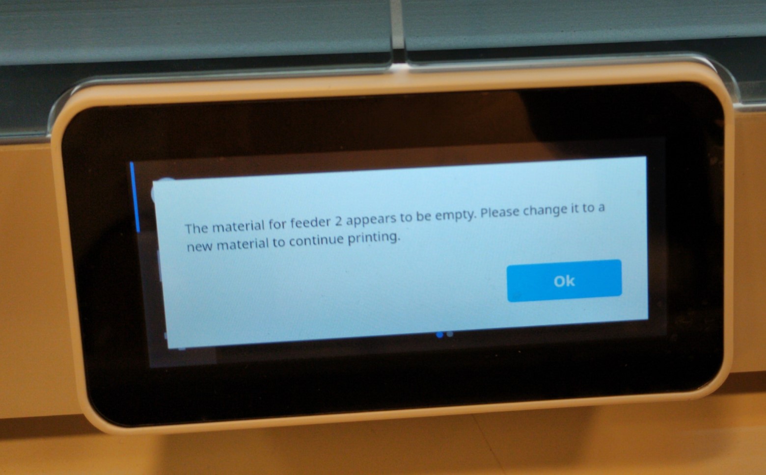
Using a different filament for the supports (PVA in this case) as I made for the Turner cube and the Sierpiński triangle.
For me it was really a nightmare because of the printer was complaining about the material and the printing was stopping like every 10-15mins. I still have no idea if the Ultimaker S5 doesn’t like this filament in general (even when the filament was also Ultimaker 😅), or if it’s a problem of the firmware (6.3.0 at this moment); I discard a problem on this printer itself cause I tried with another Ultimaker S5 and had the same problem… maybe it was the firmware.
In the case that you use this material… it is water soluble, so you just need to soak it for some hours removing at the beginning as much material as you can with pliers or something else, there is no need to use hot water or put it in the washing machine 🤷🏽♂️. -
Using the Tree type support as I made with Mini Jeff:
Something that catches my attention is that… since it’s an empty shell (I mean that it has no infill), it needs a bit less filament, takes less time, and the best part… it doesn’t damage other parts of your printing when removing it. I love it!
Files and references
- SierpinskiTriangle.scad
- TurnerCube.f3d
- TurnerCube.stl
- MINI All In One 3D printer test
- 3DBenchy
- Shah, J. & Snider, B. & Clarke, T. & Kozutsky, S. & Lacki, Maciej & Hosseini, Ali. (2019). Large-scale 3D printers for additive manufacturing: design considerations and challenges. The International Journal of Advanced Manufacturing Technology. 104. 1-15. 10.1007/s00170-019-04074-6.