8. Computer controlled machining | Modular table
- Test runout, alignment, speeds, feeds, and toolpaths for your machine. Document your work (in a group or individually):
My individual part: I have documented it in the Reviewing the machine.
Group assignment page: here, which contains also the runout test practice.
- Make (design+mill+assemble) something big:
My idea for this assignment was to make a ‘modular’ circular table, which is basically made of 4 small tables that you can take separately using:
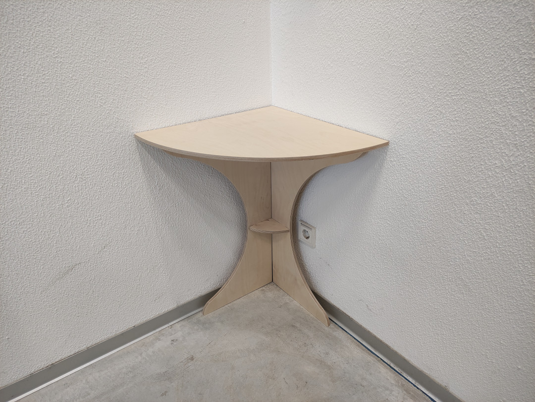
- 1 table in the corner of a room.
- 2 tables against the wall.
- 4 tables together in the of the room.
Reviewing the machine
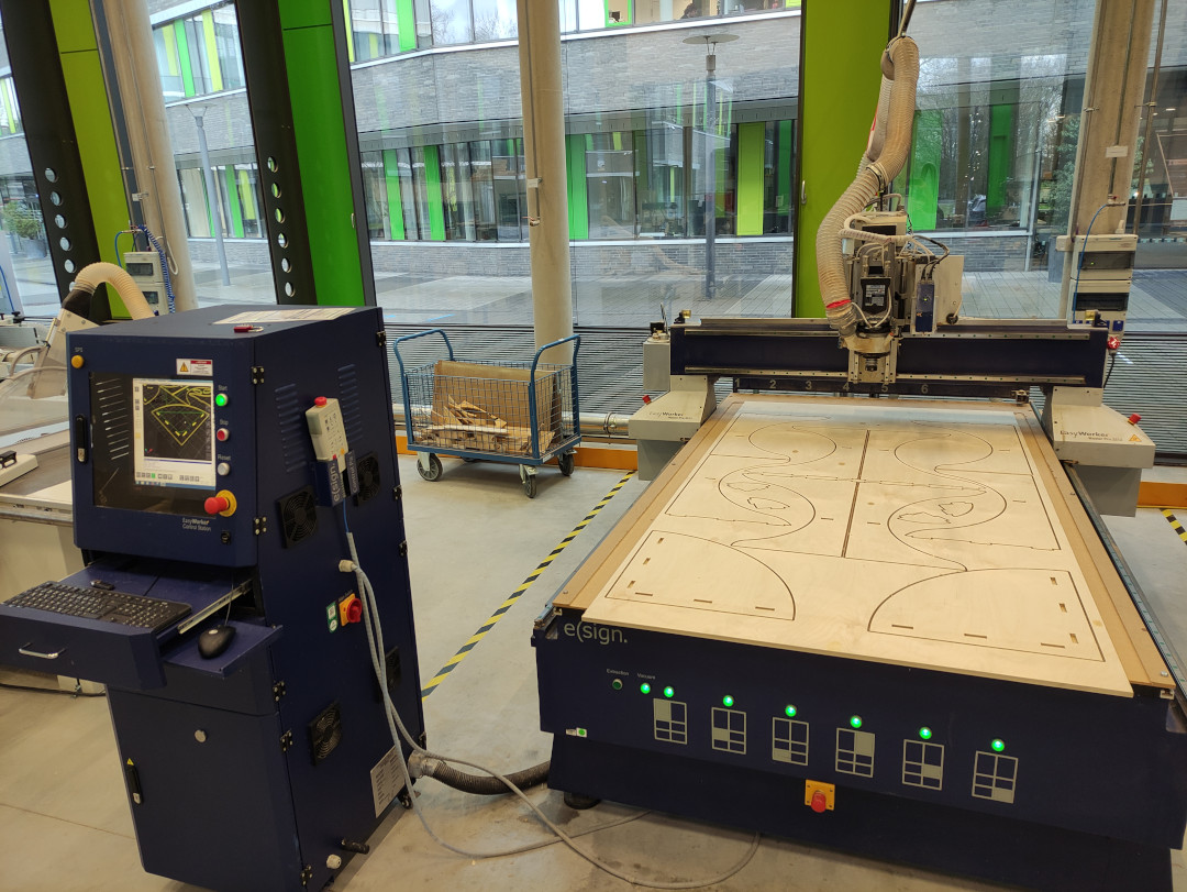
The CNC machine I used was the EasyWorker MasterPro 2513.
The first thing we have to do is checking the datasheet from the machine which we can find in the website, the most important aspects are:
- Working area: 2600 x 1400 x 300mm
- Dimension: 3200 x 2300 x 1700mm
- Max. speed: up to 19.000mm/min
Testing press fit
-Wooden material thickness: 17.3mm
- I cut two male tabs at 50mm width and 50mm length.
- I cut two female tabs: one at the exact dimensions for the male one (17.3mm x 50mm), the second one with an 0.2mm offset (17.5mm x 50.2mm)
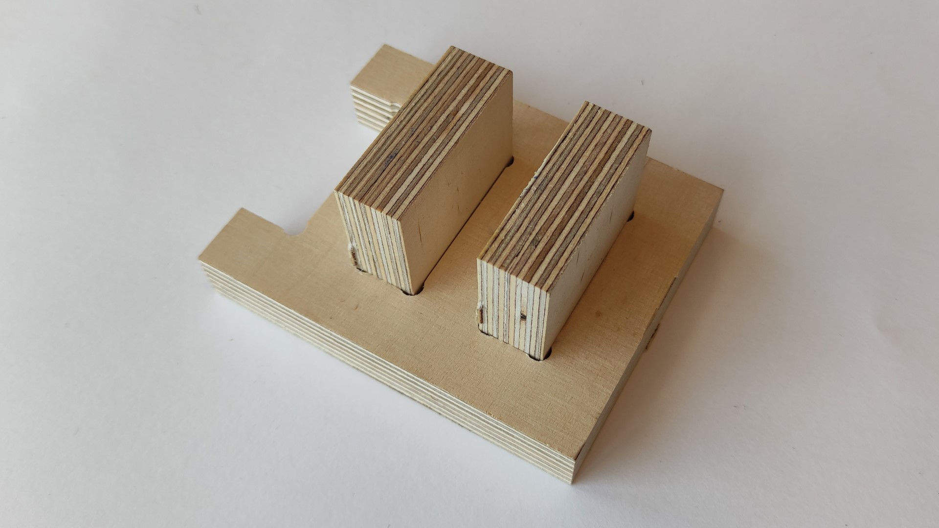
Both of them are fairly fit, but for my application I rather without the 0.2mm offset cause it makes me feel sure about no piece will fall later.
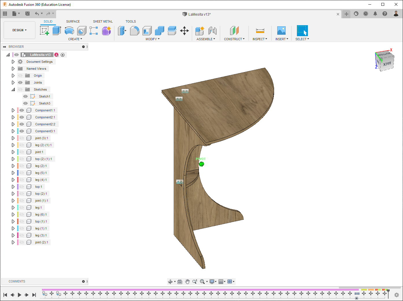
Design
For designing I used Fusion 360.
I applied Parametric design, taking as parameter the Material thickness:
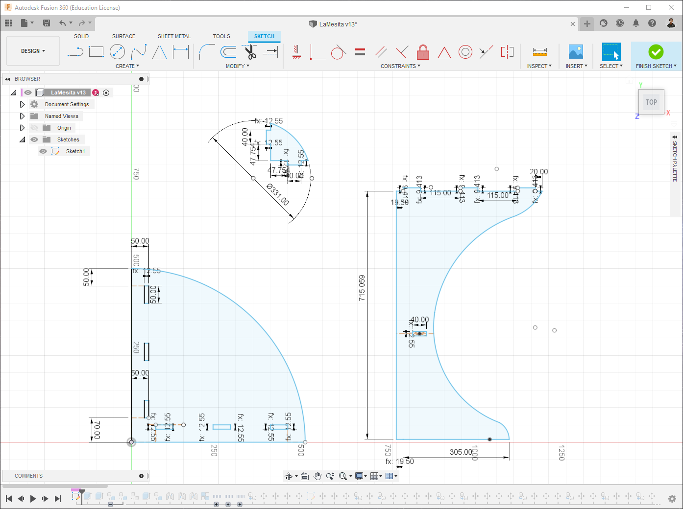
- First I made the design in 2D.
- Then I created the Bodies, made components from them.
- Since for the milling process we do not get straight corners, but rounded… we need to created them in the design, before preparing the GCode, we can do that by ourselves on the Sketch, or simply use an add-in for that.
- I used DogBone - A Fusion360 add-in that creates dogbone joints for wood joinery.
- Finally, I assembled them to make sure that all of the pieces join properly.
CNC program generation
-
First I had to multiply by 4 the basic design, in order to get a complete circular table with all of the part needed.
-
As preparation to generate the GCode, we should first arrange the parts on a “sheet”, taking the real sheet measurements. It can be done either manually or using a plug-in. I did it manually.
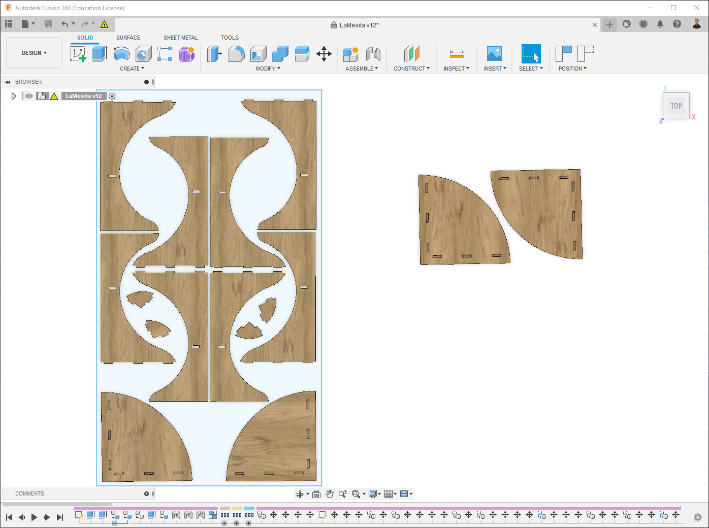
As you have probably noticed, I needed a bit more then one sheet.
Tool configuration
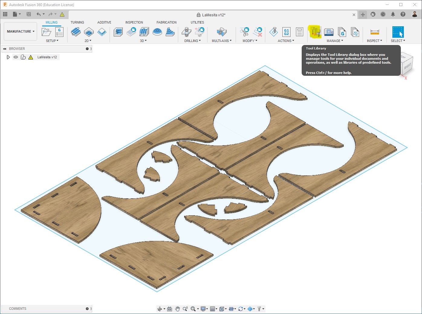
At this points I moved to the Manufacture Workspace of Fusion 360.
Fusion 360 already offers a library of tools for drilling, milling, and more; but to customize and make it fit with our reality, it’s good to configure by ourselves the tools that we are going to use.
In this case I used a 6mm flat end mill:
-
Open Milling > Manage > Tool library:
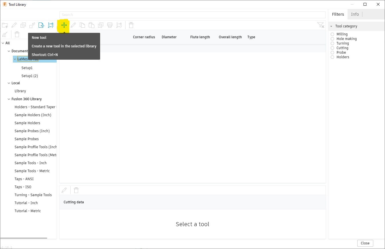
-
Create a New tool:
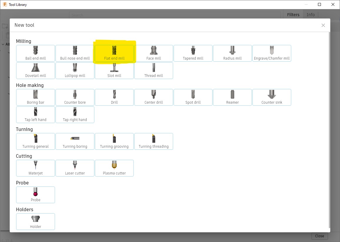
-
Select the type of tool, in my case it’s a Flat end mill:
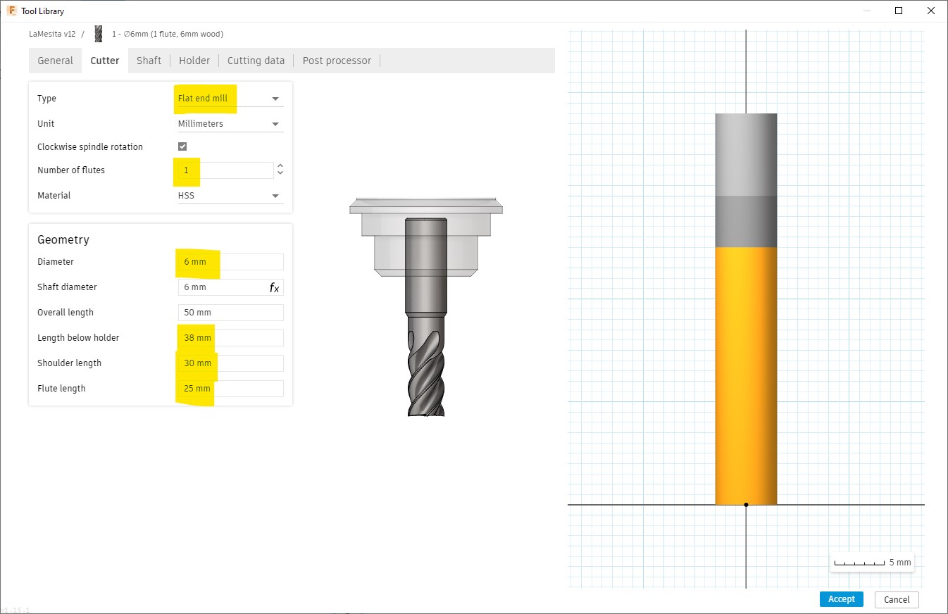
-
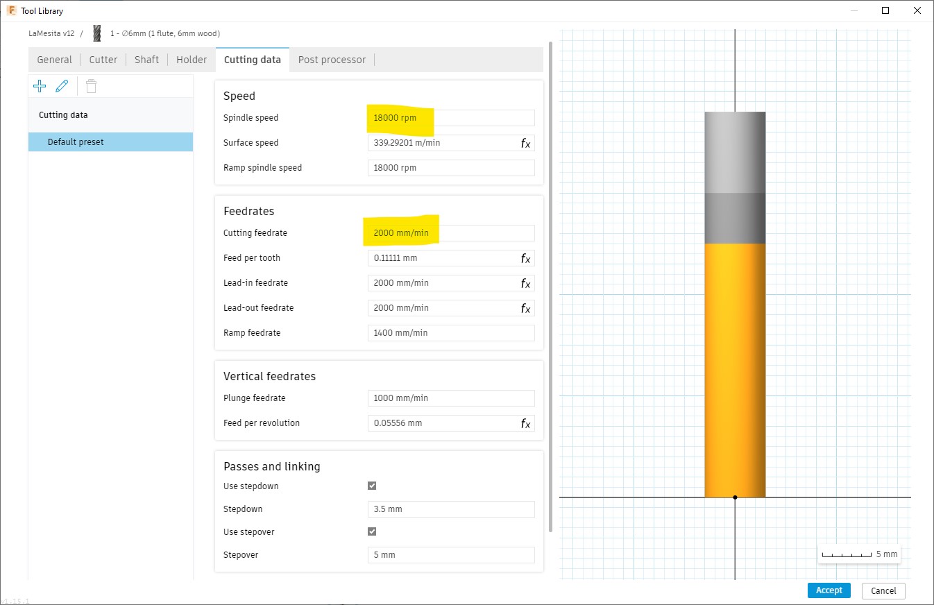
The Cutter tab is the most important to configure at this point, Cutting data can be configured independently for each process when using the same tool for more than one, also it can be easily changed during the machining. Diameter is used for creating the toolpath; and the highlighted lengths are essential afterwards, during simulation, to detect possible collisions:
-
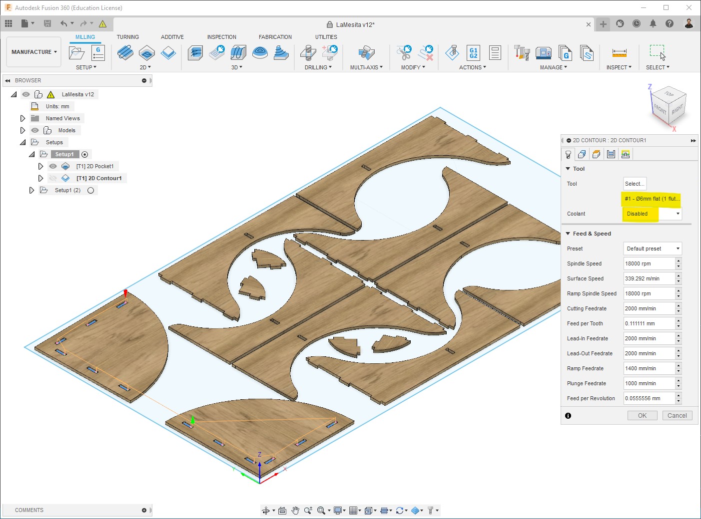
I also set the Cutting data already cause I didn’t change it in any process, just set the Spindle speed to 18,000RPM which is approximately the maximum in this machine, and cutting speed to 2,000mm/min, I left the rest of parameters calculated by default:
Setup preparation
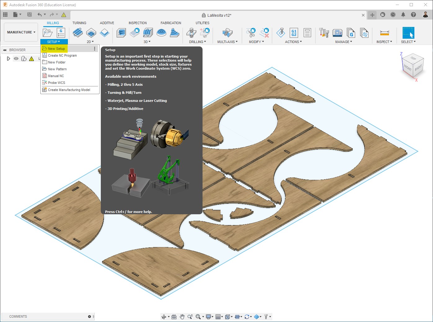
This is the first step before configuring the processes.
-
Create a New setup:
-
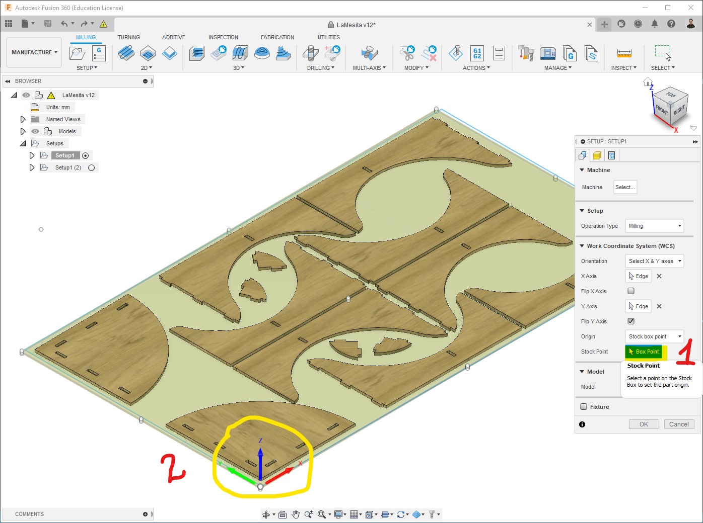
Edit the Setup:
-
Select WCS (Work Coordinate System); it depends on the machine we are going to use, in this case is on the bottom-left corner:
-
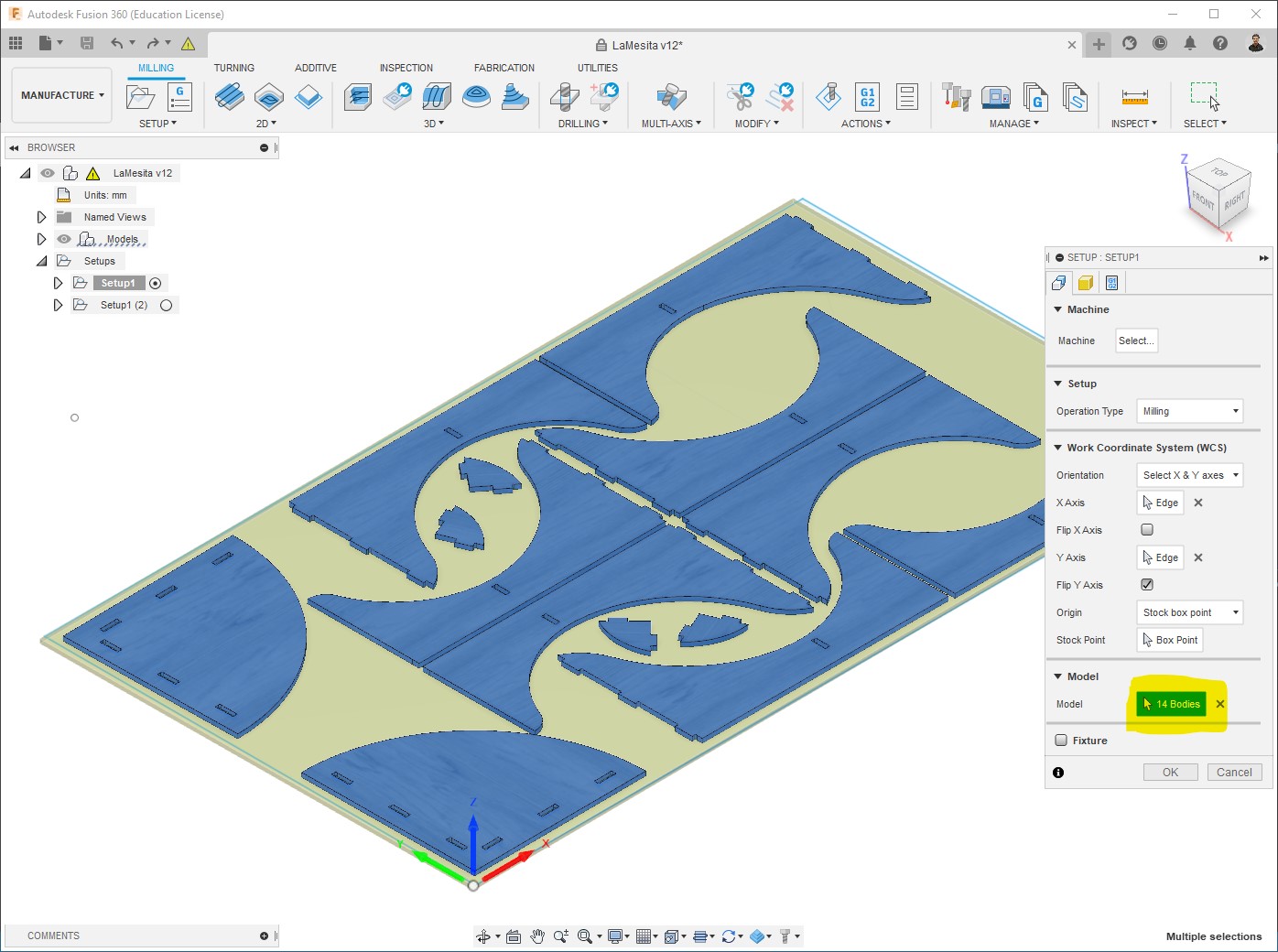
Select bodies to be machined, clicking on them:
-
I select “Fixed size box”, and introduce the Stock dimensions:
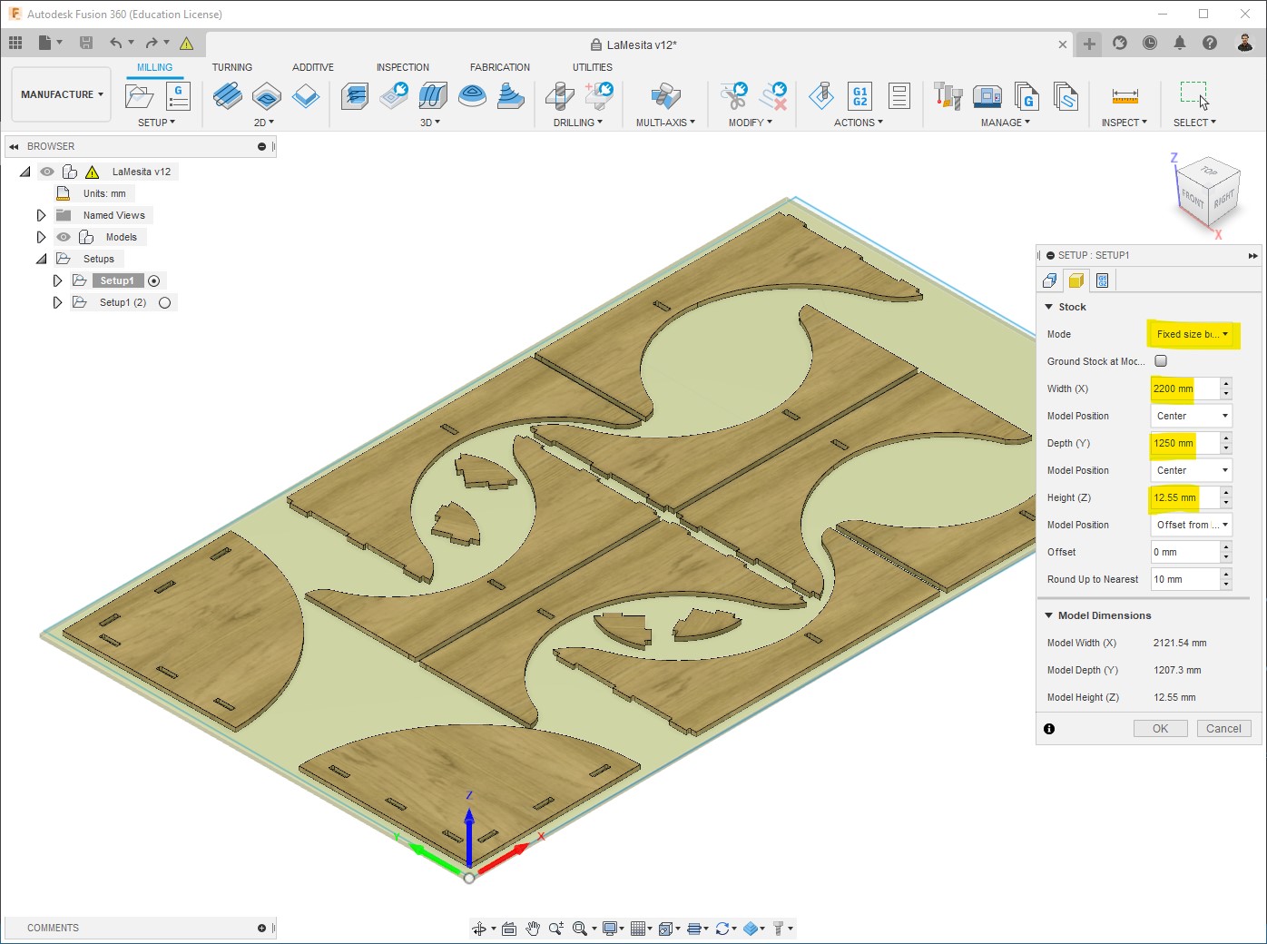
-
Processes configuration
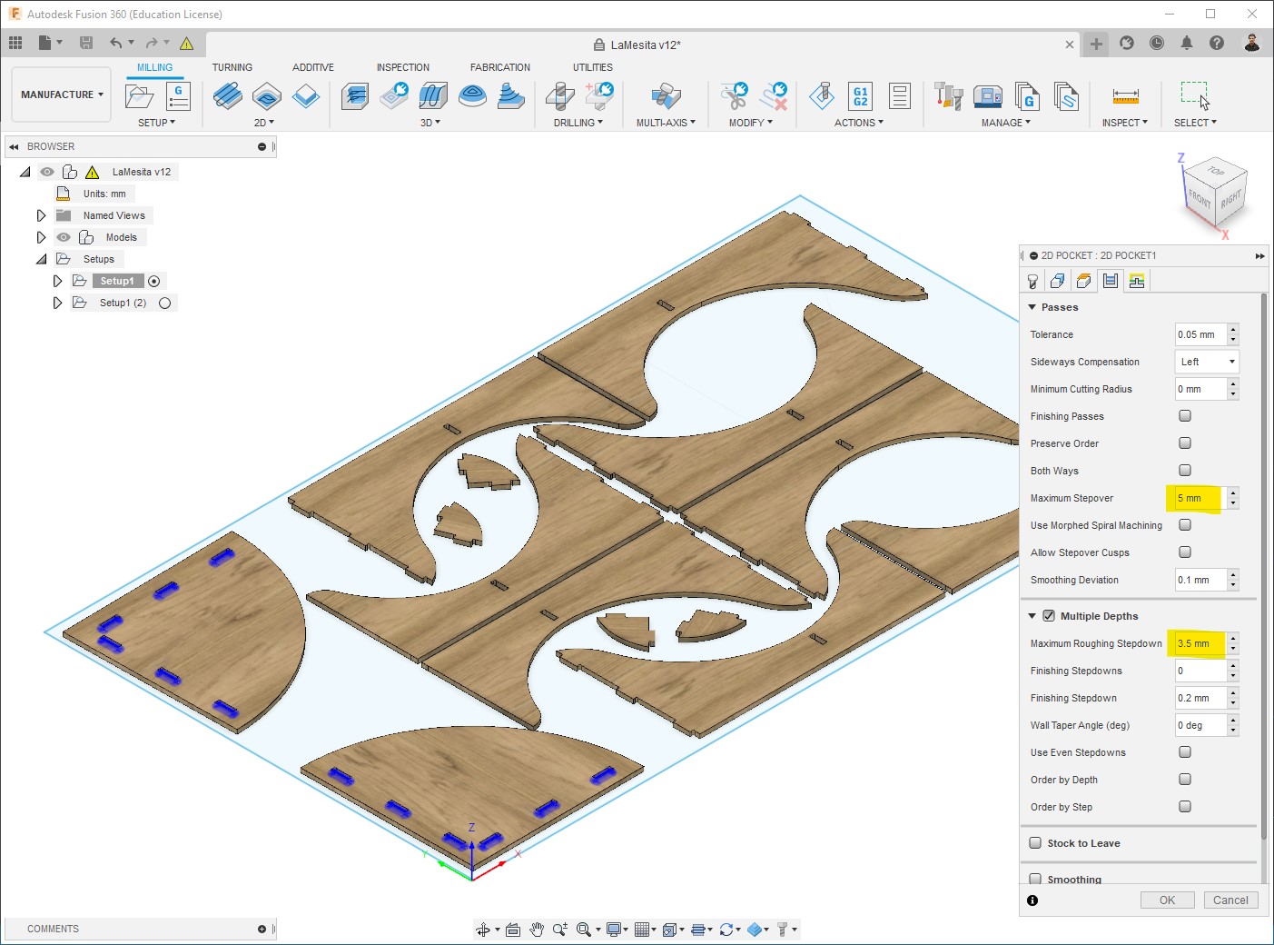
Pockets
The first process I did was making the pockets, for that I used 2D Pocket:
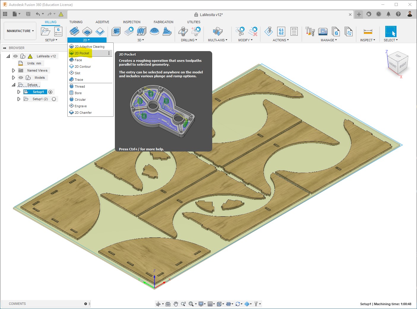
-
Select Tool:
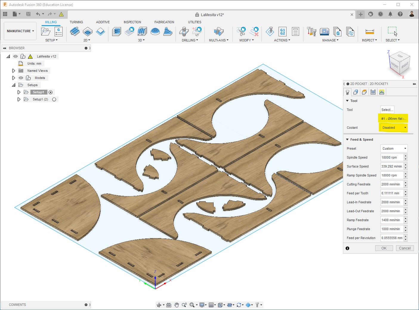
-
Select pockets to mill:
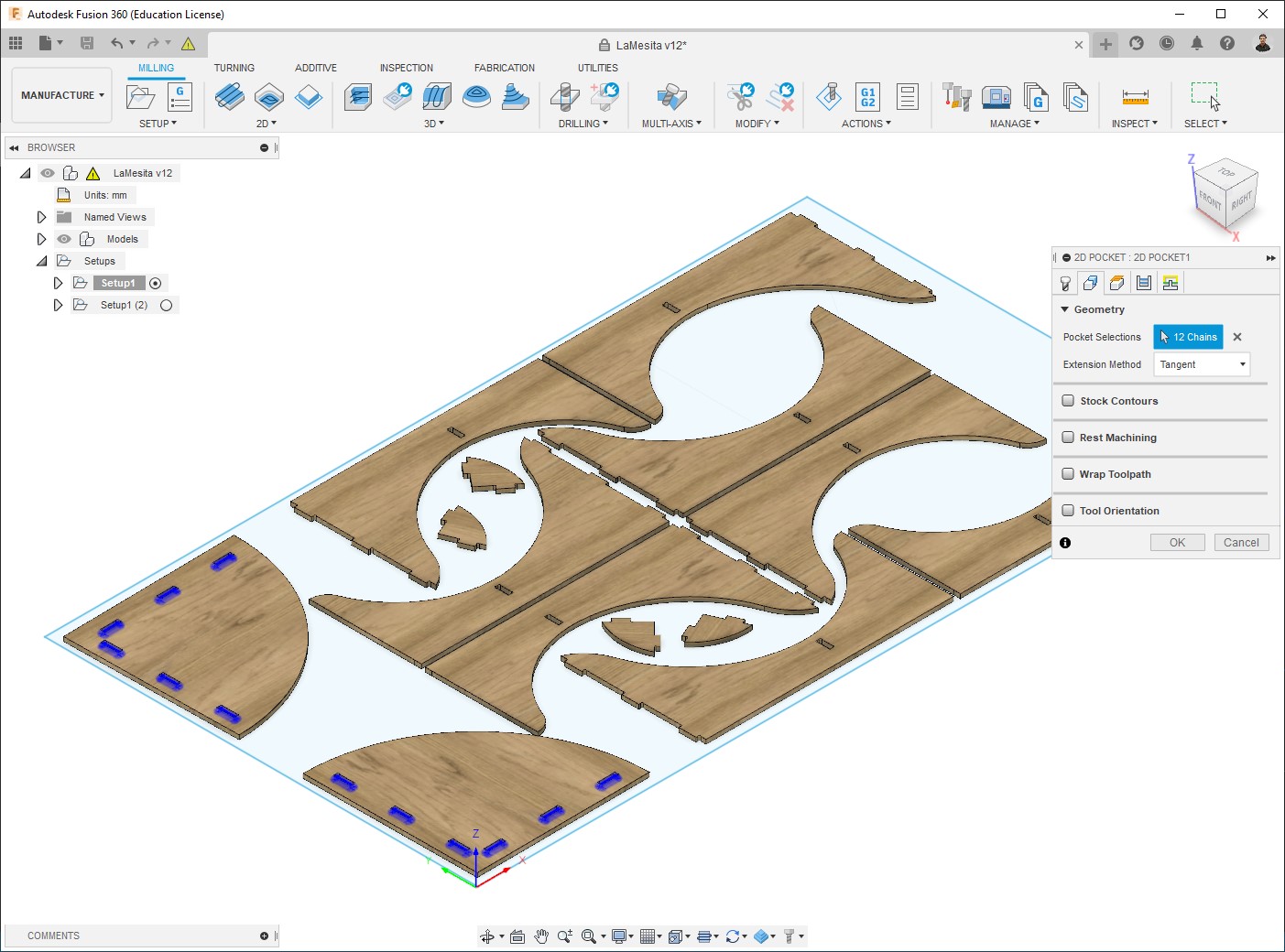
-
This is the Passes configuration that I used:
-
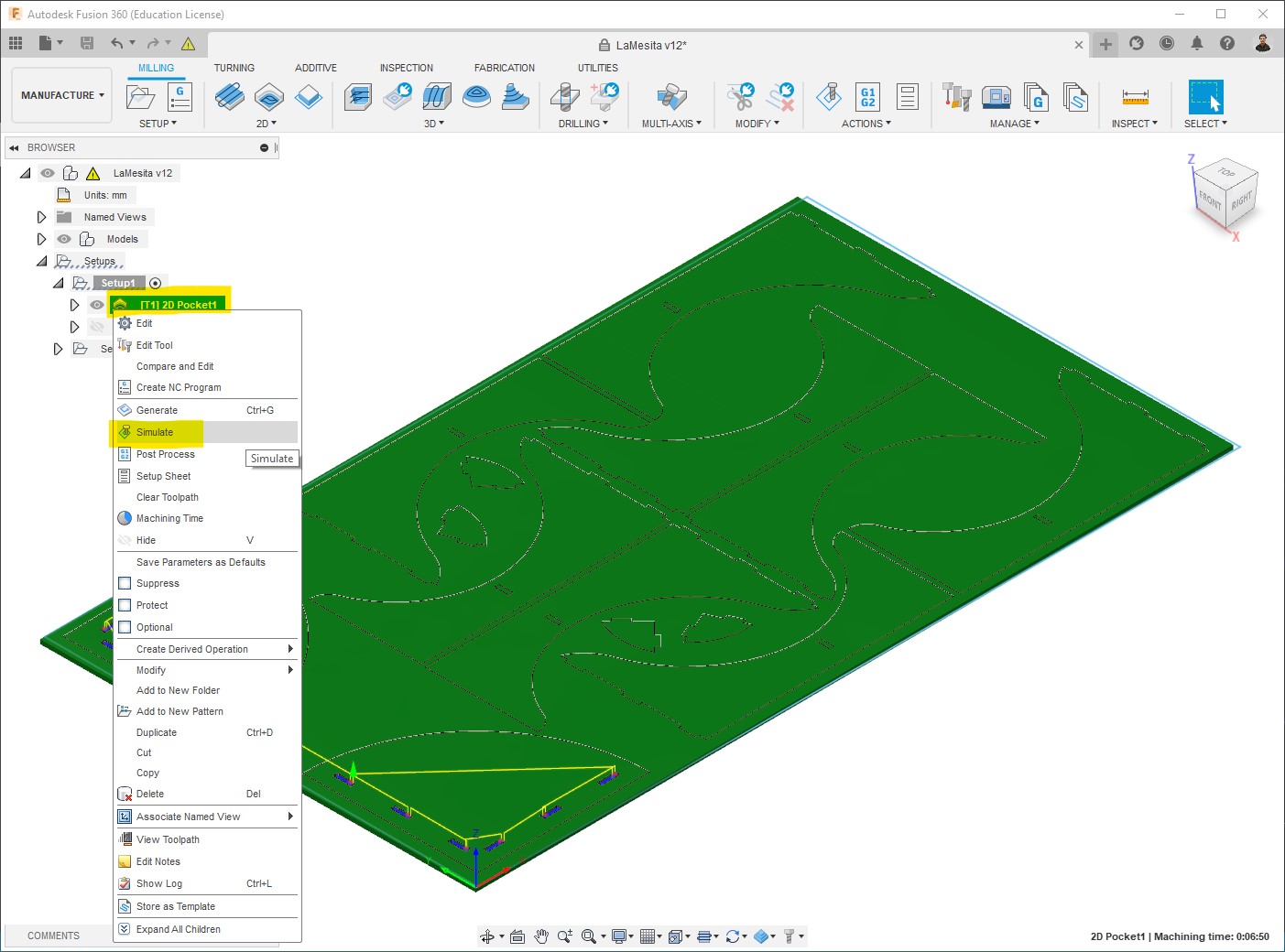
The toolpath will be generated, it could take a few seconds depending on the process, then you can see at the bottom right the machining time, which is 06mins50secs for this first process, this time is in reality just an approximate value. Next step is to Simulate:
-
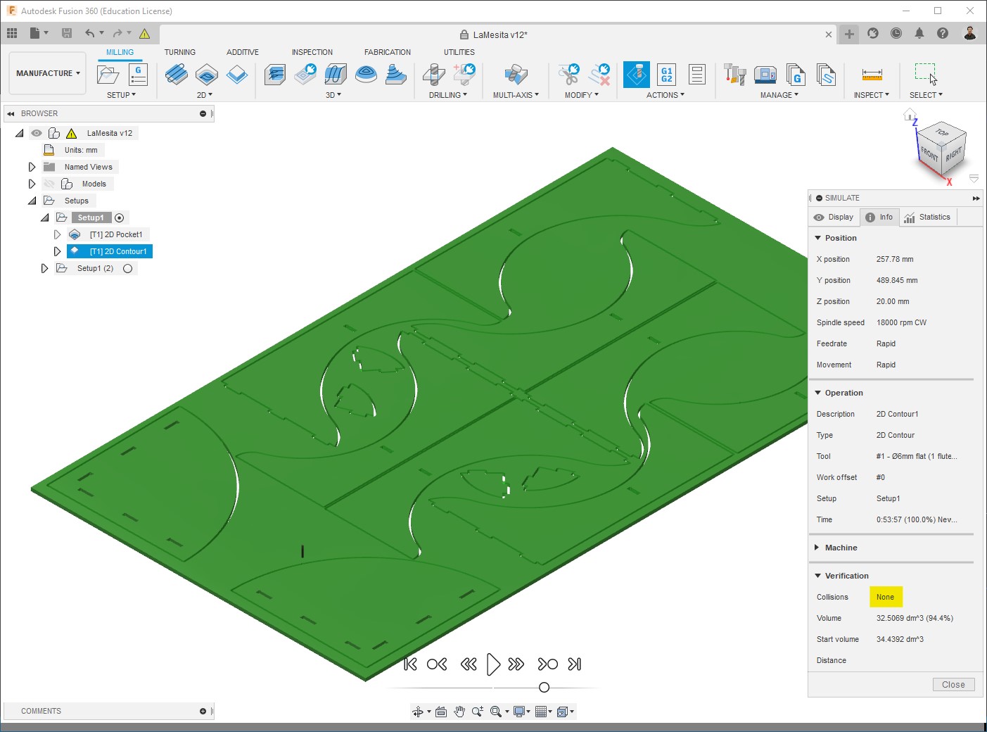
In addition to have a preview of the machining, what we need to check here is the info > Verification, to make sure that there are no Collisions:

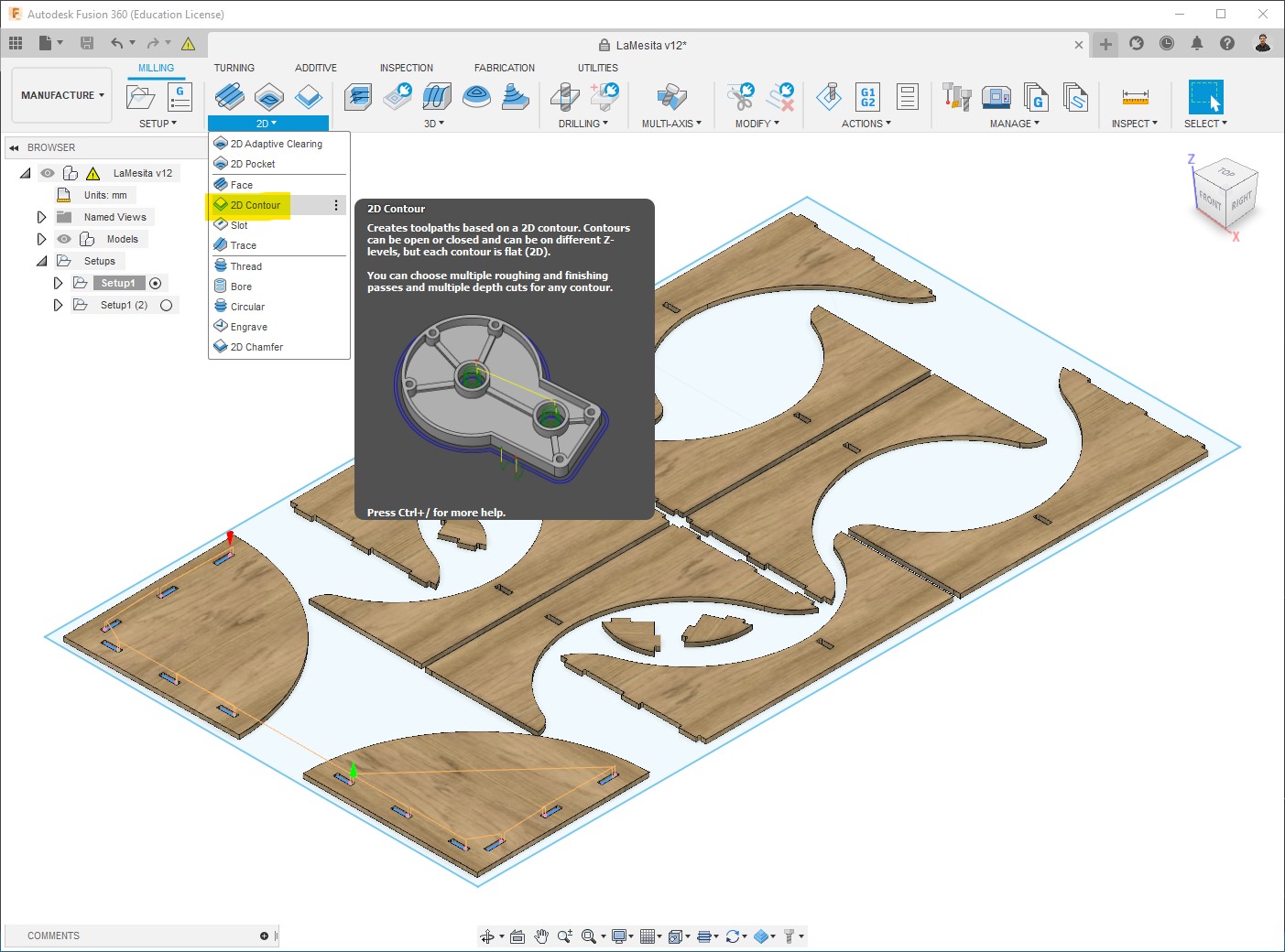
Outline
The second process consists of cutting the pieces, for that I used 2D Contour:
-
Using the same tool:
-
Select lines to cut:
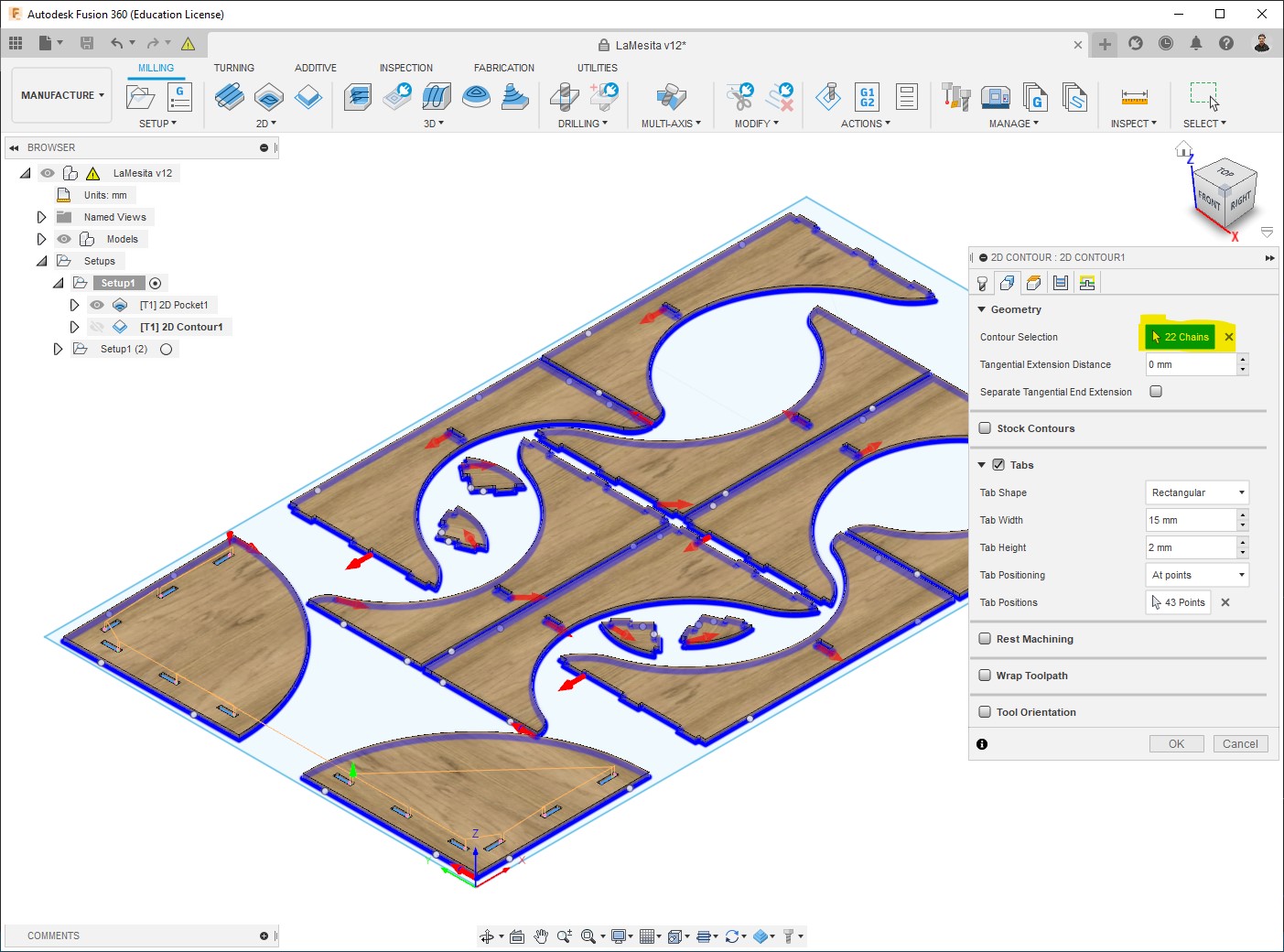
-
This is the Passes configuration that I used:
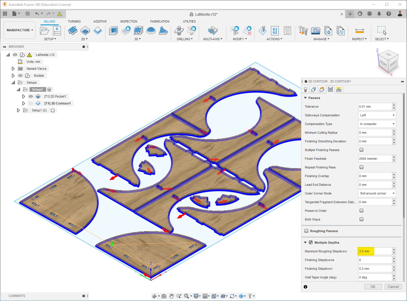
-
The toolpath will be generated. Machining time = approx 54mins:
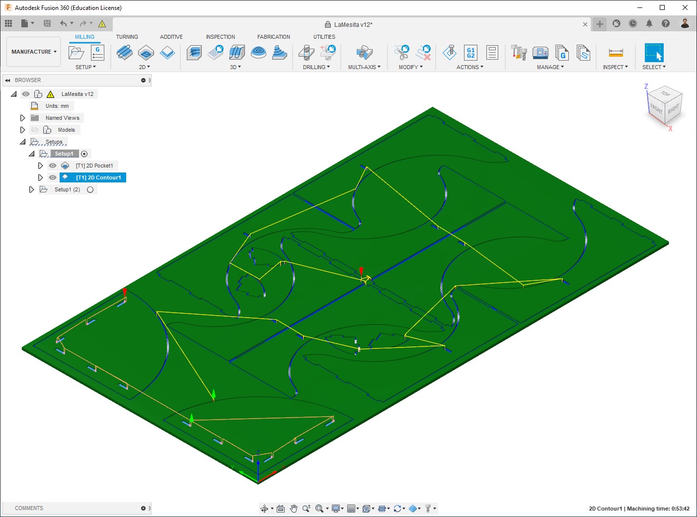
-
No collisions:
Program generation
Once we have our toolpaths and made sure there are no collisions, we can create the Numerical control (NC) program. It is also done on the Manufacture workspace.
-
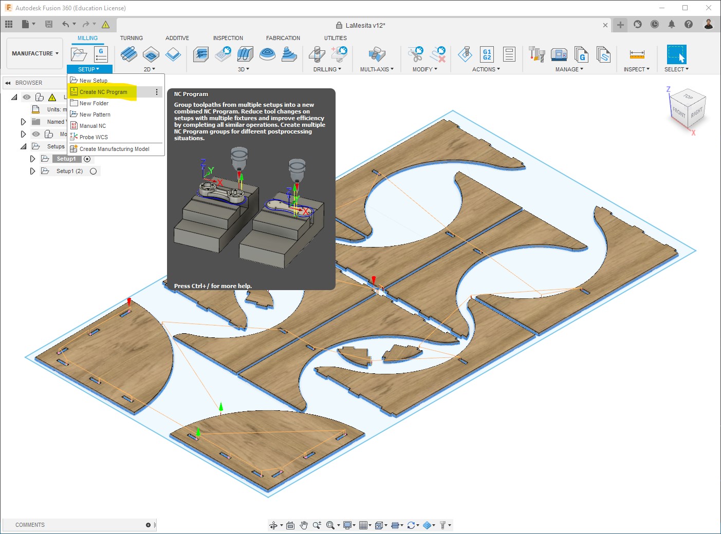
Milling > Setup > Create NC program:
-
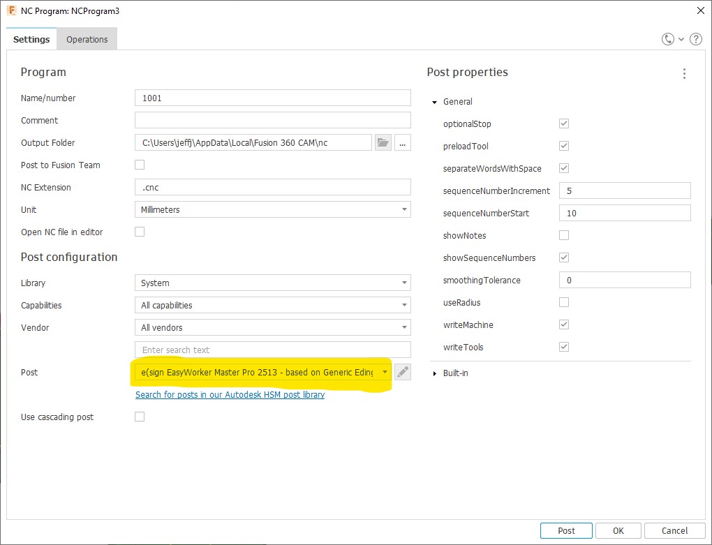
In Settings what we need is to configure the machine to use:
-
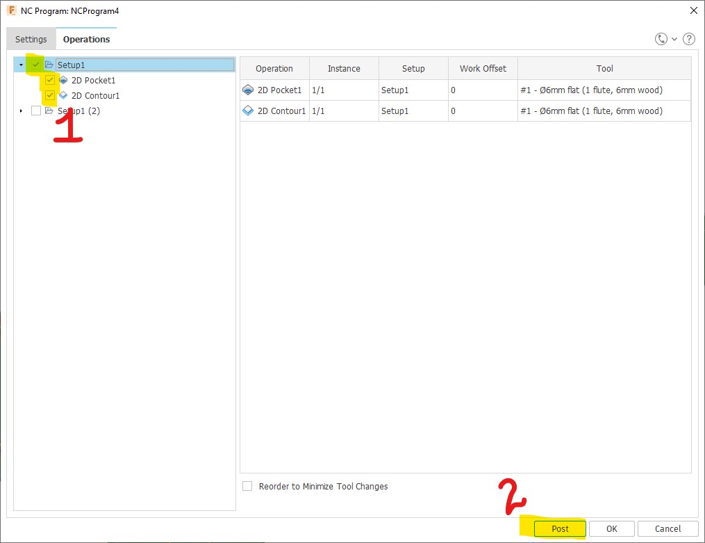
In Operations we just need to select the processes for which we want to create the program, then Post:
-
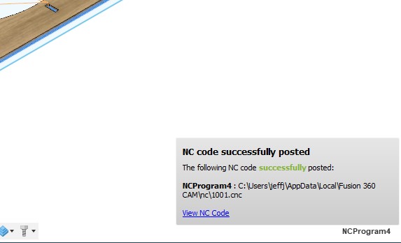
Done!
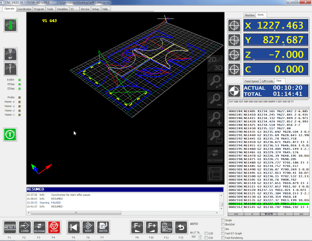
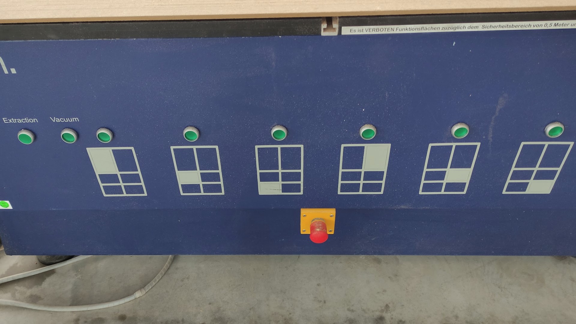
Milling
The CNC machine I used was the EasyWorker MasterPro 2513 with the CNC4.01 software.
Safety measurements when working on the CNC machine
- Make sure that the bed is flat.
- Wear safety goggles.
- Wear ear plugs.
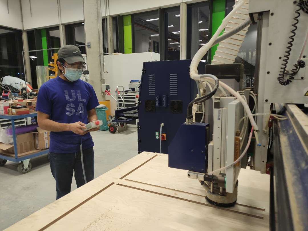
Process
-
First, we move to the Machine home:
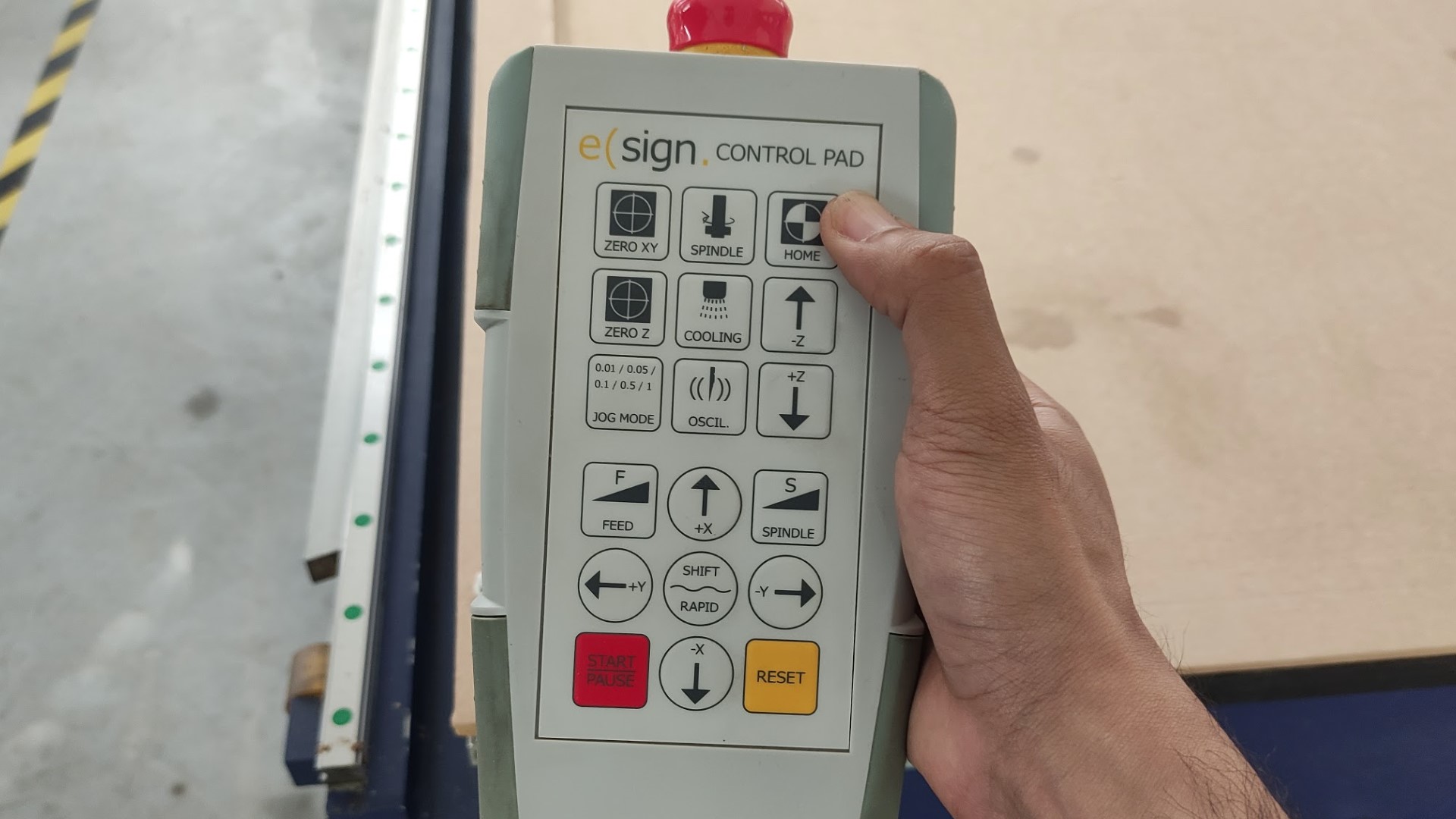
-
Second, set the Zero XY point on the sheet:
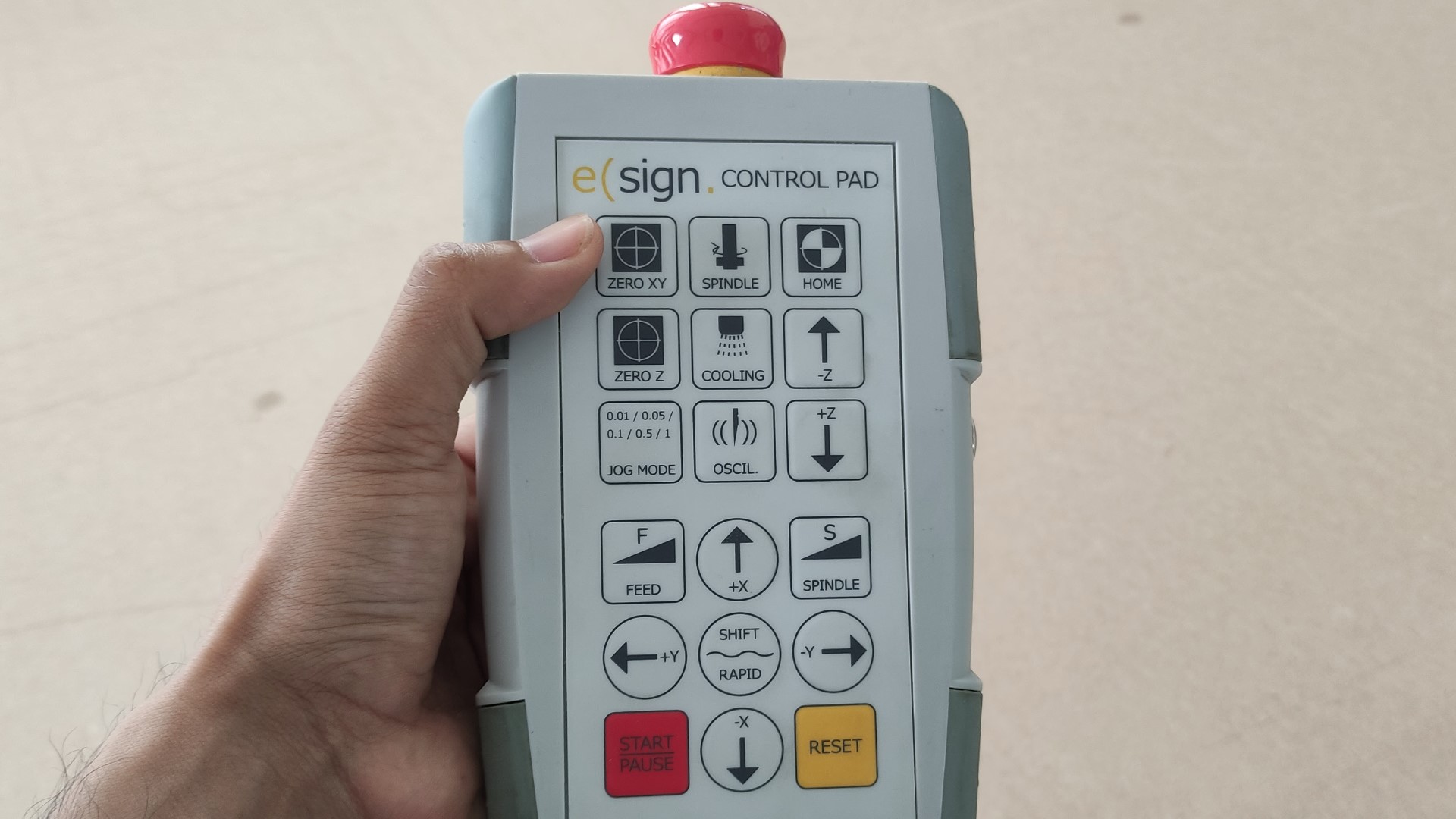
-
Set Z point.
-
Before start milling, we need to make sure that we have activated the Vacuum and the Extraction system.
-
Make sure that the dust cover comes down before it starts milling.
- Launch the code to start milling.
A sanding post-process is needed.
Assemble
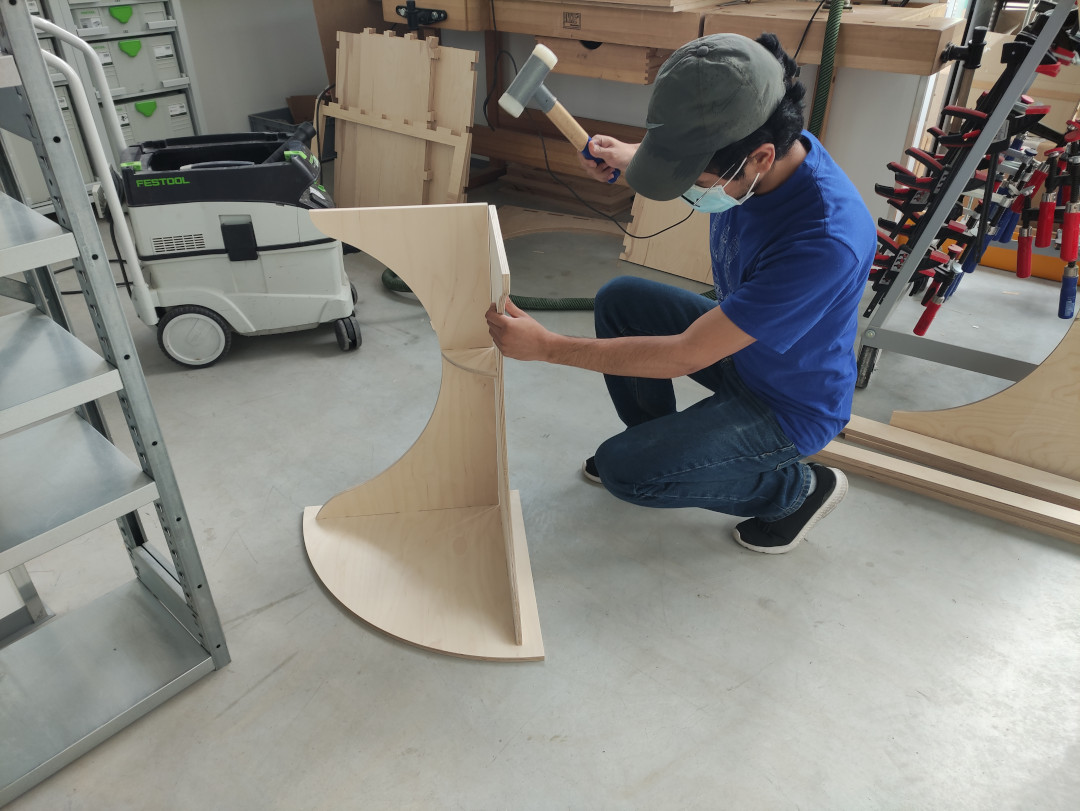
Since the assembly doesn’t need any extra components, all I had to do is just hammer the pieces to get stable joints without screws or glue.
Result
- 1 table in the corner of a room:
- 2 tables against the wall:
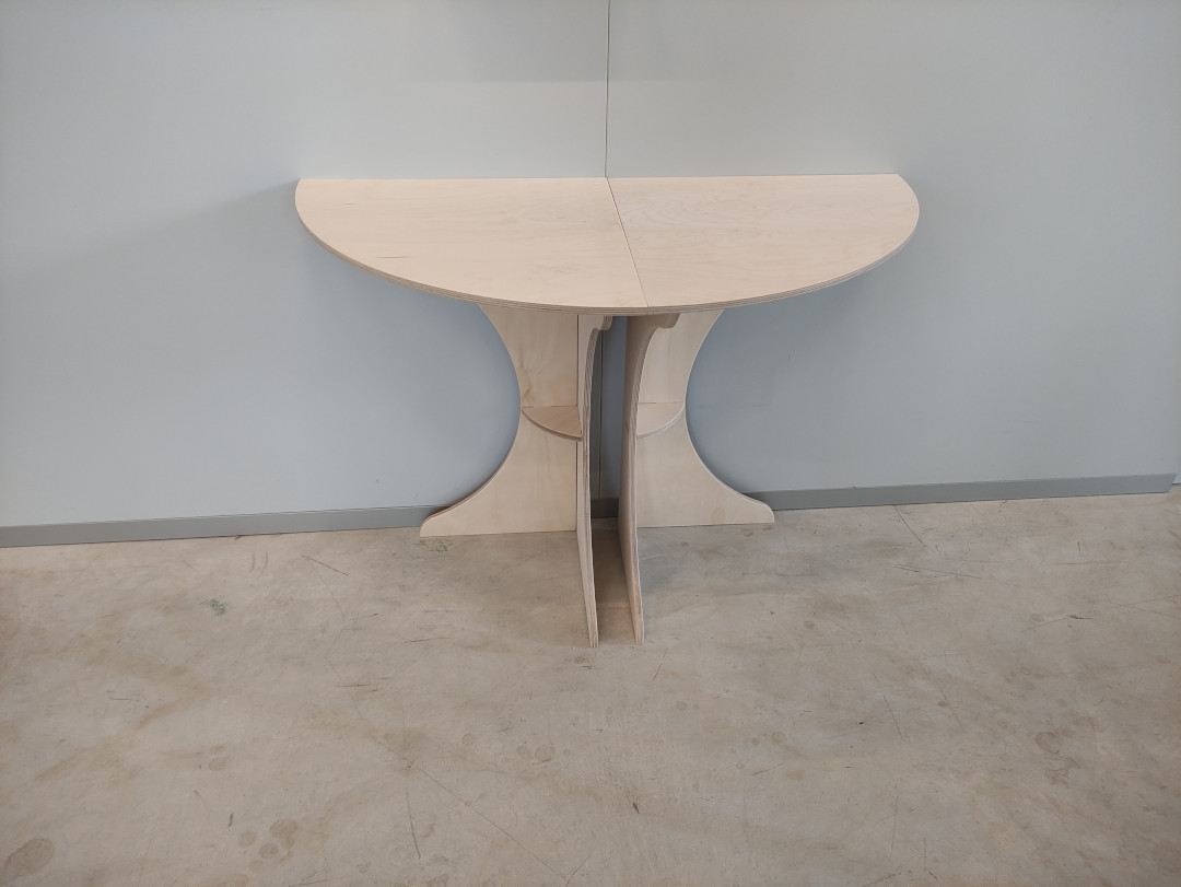
- 4 tables together in the of the room:
Assignment outlook
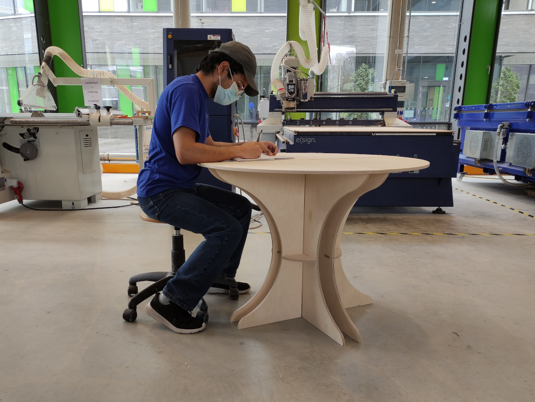
As you may have noticed, the bottom part of the legs are rather short, which was really my intention cause the result is has a very elegant look for me; but when it comes to real usage that doesn’t work, cause it makes the table (either in separated pieces or together) very unstable:
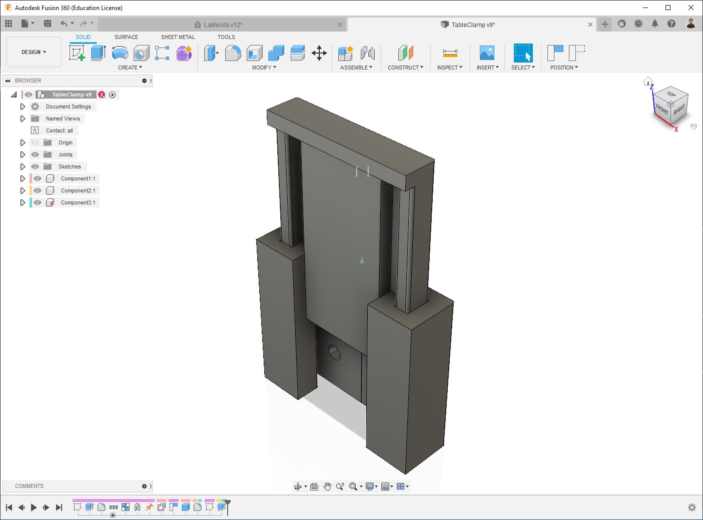
Since re-designing and re-cut it wasn’t an option for me cause of my time and my instructor’s (also the restricted access to the lab due to Corona regulations), then I 3D printed a clamp to joint the pieces together so they stabilize each other:
Then yes, I couldn’t use it in individual pieces, at least two pieces need to be used together.
At the end a good consideration I get out of it is making the legs at least the diameter of the top board, and also make a scaled prototype beforehand, one laser cut could be.
Files
- ModularTable.f3d
- TableClamp.f3d