"Hello Everyone Week 9 Input devices get started.In this week we are going to do read the input value through any sensor that may be analog /digital one and after sensing the input value we will given to our microcontroller to processed that raed input value .Once we finished this one we can display it or we can used this value to run any other applicationns as well.So lets explore this week!
Learn Differnt Sensors
Hero Shot
- Probe an input device's analog levels and digital signals
Group Assignment
- Design a a microcontroller board
- Add a sensor to a microcontroller board that you have designed
- Read the data from Sensors
Individual assignment
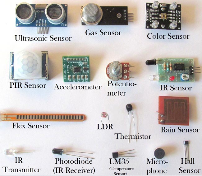
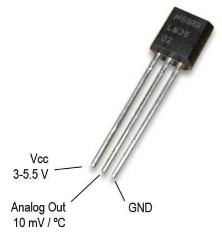
About LM 35 Sensor:

A sensor is a device that detects and responds to some type of input from the physical environment. The specific input could be light, heat, motion, moisture, pressure, or any one of a great number of other environmental phenomena.

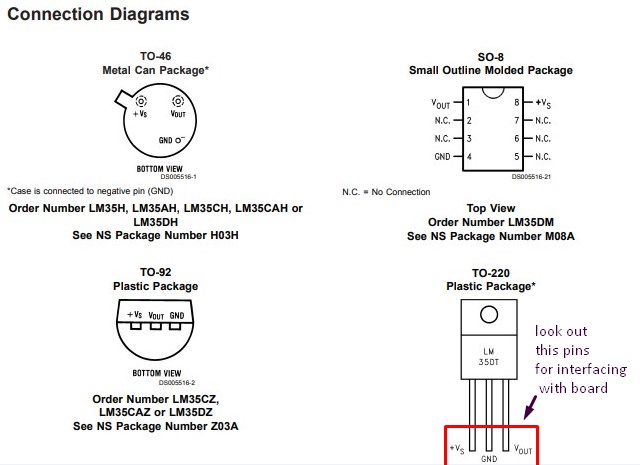
LM35 is a temperature sensor that outputs an analog signal which is proportional to the instantaneous temperature. The output voltage can easily be interpreted to obtain a temperature reading in Celsius.
Read more about LM35 temperature sensor pin out, interfacing guide, circuit construction and working principals.
About Microcontroller 328p Board Design
After understsnding about sensors like the LM 35 and others now the next work is to know about the another family of AVR microcontroller.

Lets try to find out answer of above.As we want to read the data from sensor i.e.input devices and then to display it on any console like serial monitor.To finished this one we need one brain and microcontroller acts like brain of the computer.Here microcontroller process the input data from sensors and display it on console.

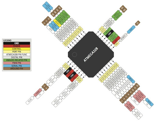
The high-performance, low-power Microchip AVR RISC-based CMOS 8-bit microcontroller combines 4KB ISP flash memory, 256-Byte EEPROM, 256B SRAM, 12 general purpose I/O lines, 32 general purpose working registers, an 8-bit timer/counter with two PWM channels, a 16-bit timer/counter with two PWM channels, internal and external interrupts, an 8-channel 10-bit A/D converter, a programmable gain stage (1x, 20x) for 12 differential ADC channel pairs, programmable watchdog timer with internal oscillator, a internal calibrated oscillator, and three software selectable power saving modes. By executing powerful instructions in a single clock cycle, the device achieves throughputs approaching 1 MIPS per MHz, balancing power consumption and processing speed.

When i compare atmega 328p with others i found some basic features of ATmega 328p.
- ● High performance, low power AVR® 8-bit microcontroller
- ● Advanced RISC architecture
- ● 131 powerful instructions – most single clock cycle execution
- ● 32 -8 bit general purpose working registers
- ● Fully static operation
- ● Up to 16MIPS throughput at 16MHz
- ● On-chip 2-cycle multiplier
- ● High endurance non-volatile memory segments
- ● 32K bytes of in-system self-programmable flash program memory
- ● 1Kbytes EEPROM
- ● 2Kbytes internal SRAM
- ● Write/erase cycles: 10,000 flash/100,000 EEPROM
- ● Optional boot code section with independent lock bits
- ● In-system programming by on-chip boot program
- ● True read-while-write operation
- ● Programming lock for software security
- ● Peripheral features
- ● Two 8-bit Timer/Counters with separate prescaler and compare mode
- ● One 16-bit Timer/Counter with separate prescaler, compare mode, and capture
mode
- ● Real time counter with separate oscillator
- ● Six PWM channels
- ● 8-channel 10-bit ADC in TQFP and QFN/MLF package
- ● Temperature measurement
- ● Programmable serial USART
- ● Master/slave SPI serial interface
- ● Byte-oriented 2-wire serial interface (Phillips I2
C compatible)
- ● Programmable watchdog timer with separate on-chip oscillator
- ● On-chip analog comparator
- ● Interrupt and wake-up on pin change
- ● I/O and packages
- ● 23 programmable I/O lines
- ● 32-lead TQFP, and 32-pad QFN/MLF

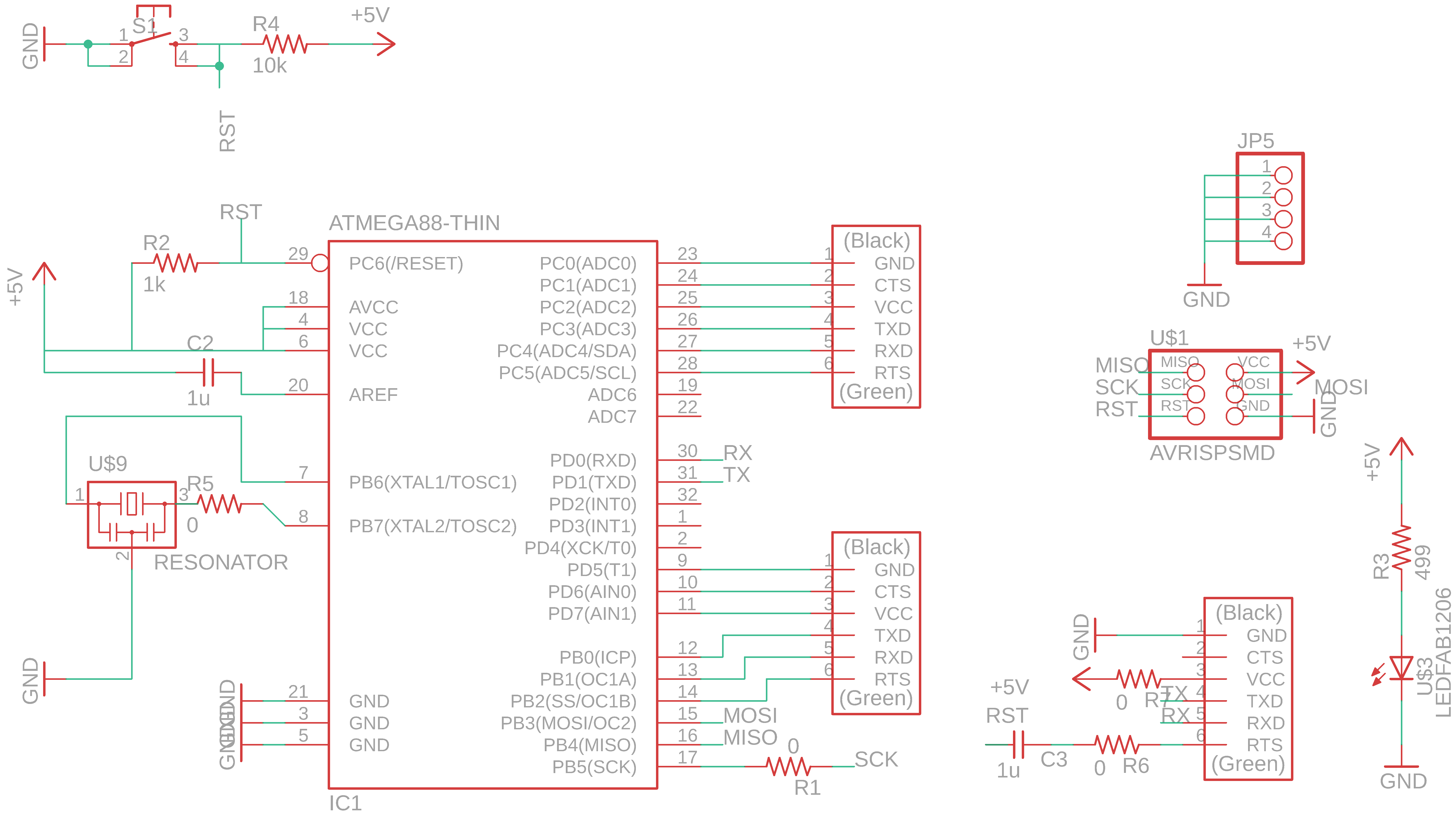
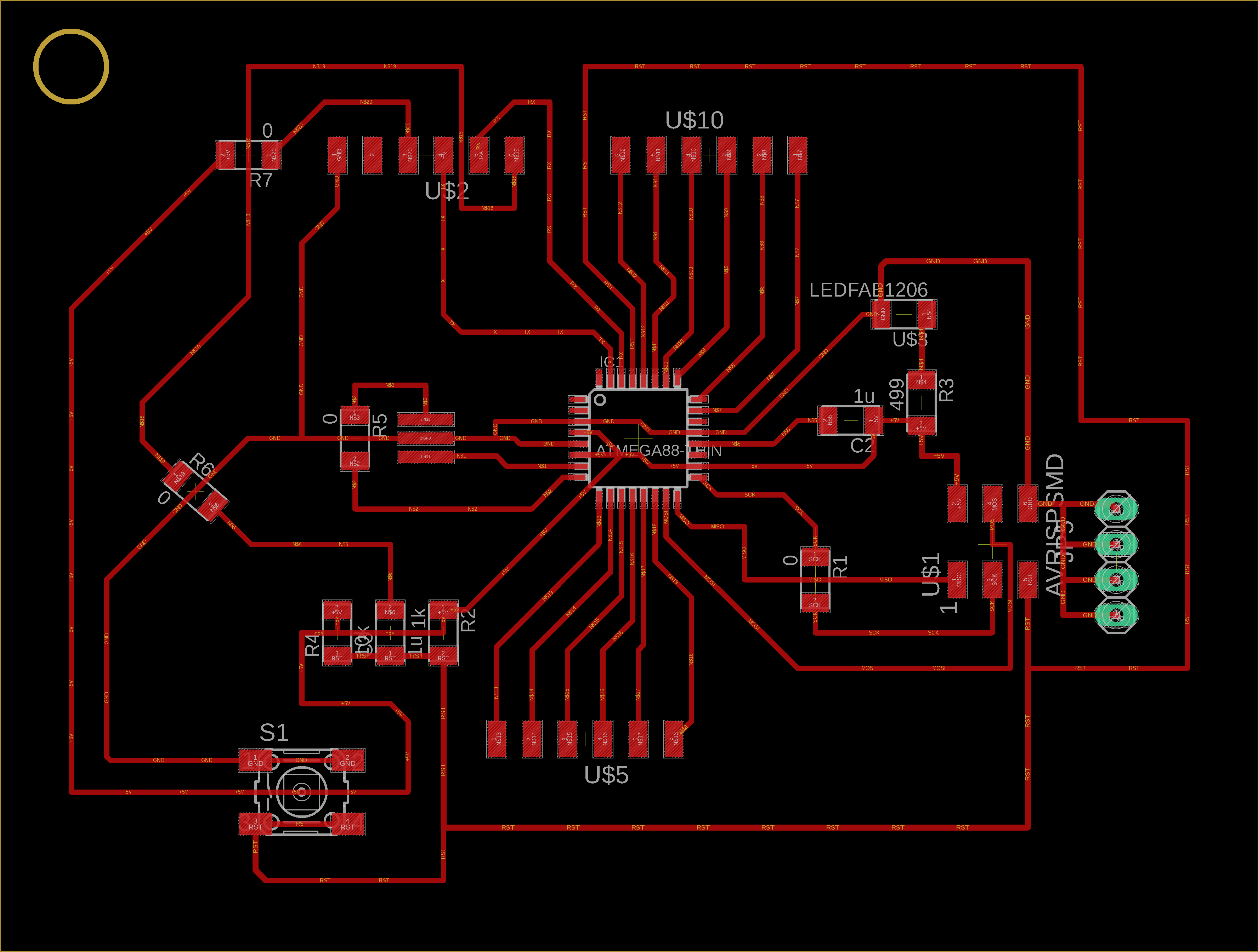
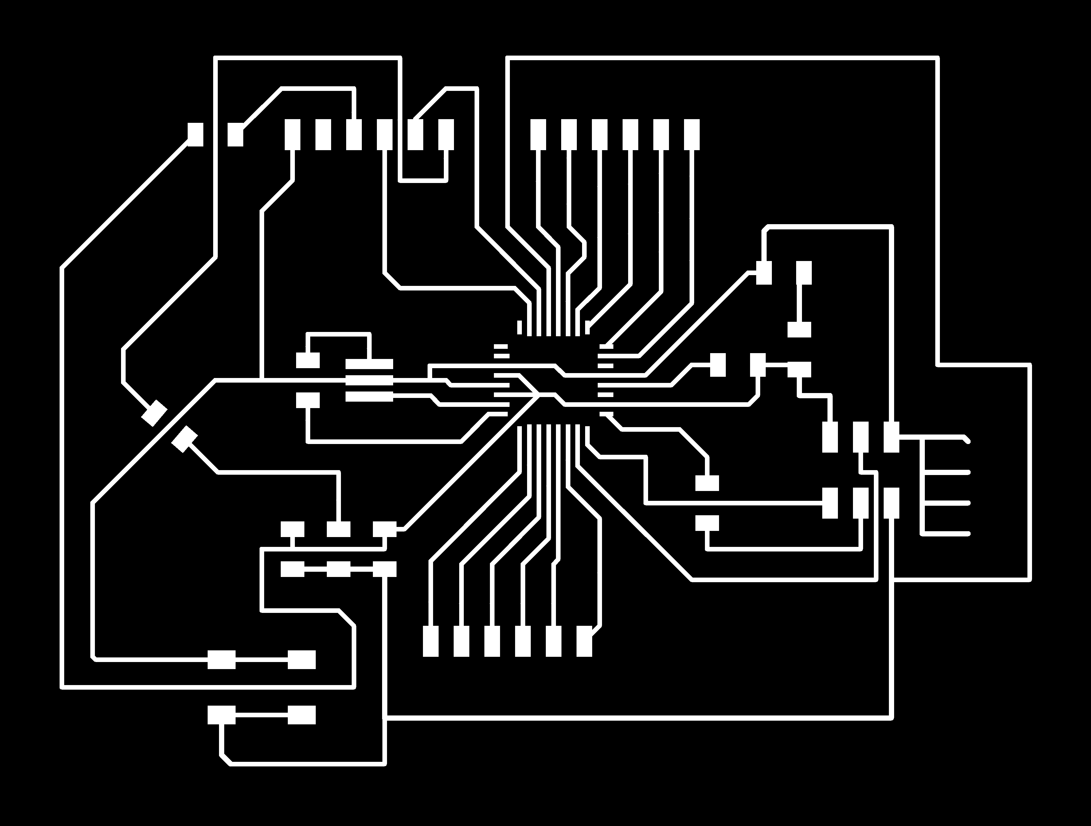
Schematic & Board of Atmega 328p in Eagle
Once we undestood the role of microcontroller with input devices now we will design a schematic and board of atmega 328p.Here I shown you my eagle schematic of ATmega 328p.In this schematic i tried to have AVR ISP header pins ,FTDI headres ,Crystal oscillators reset buttons and one led.After having this some pins are left out for that i used one pin heder so that i can used these pins later.


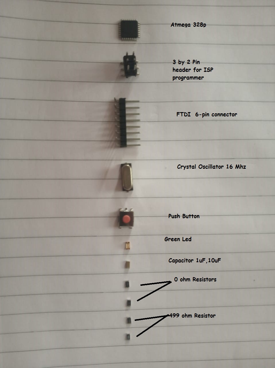
Componant List
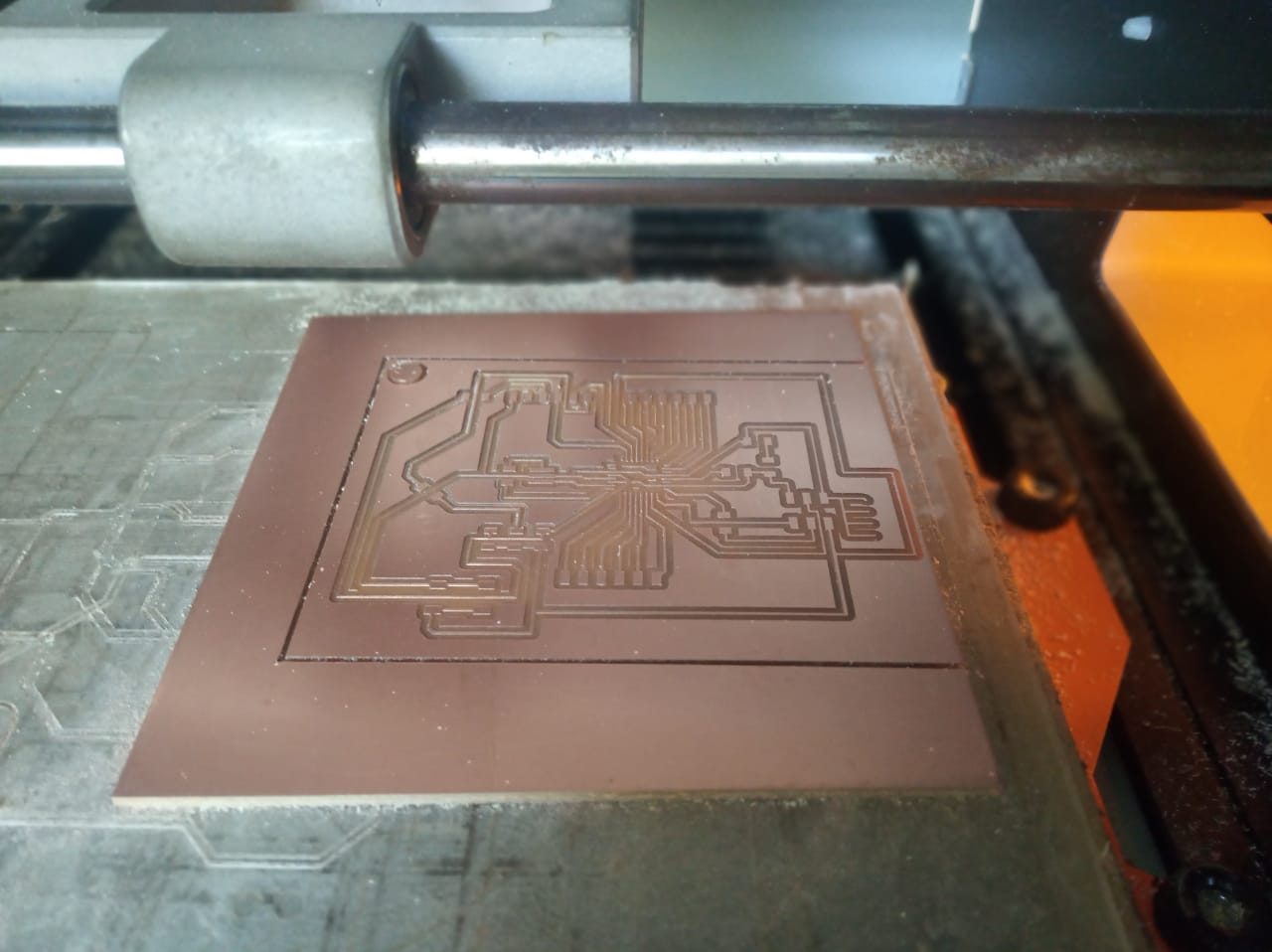
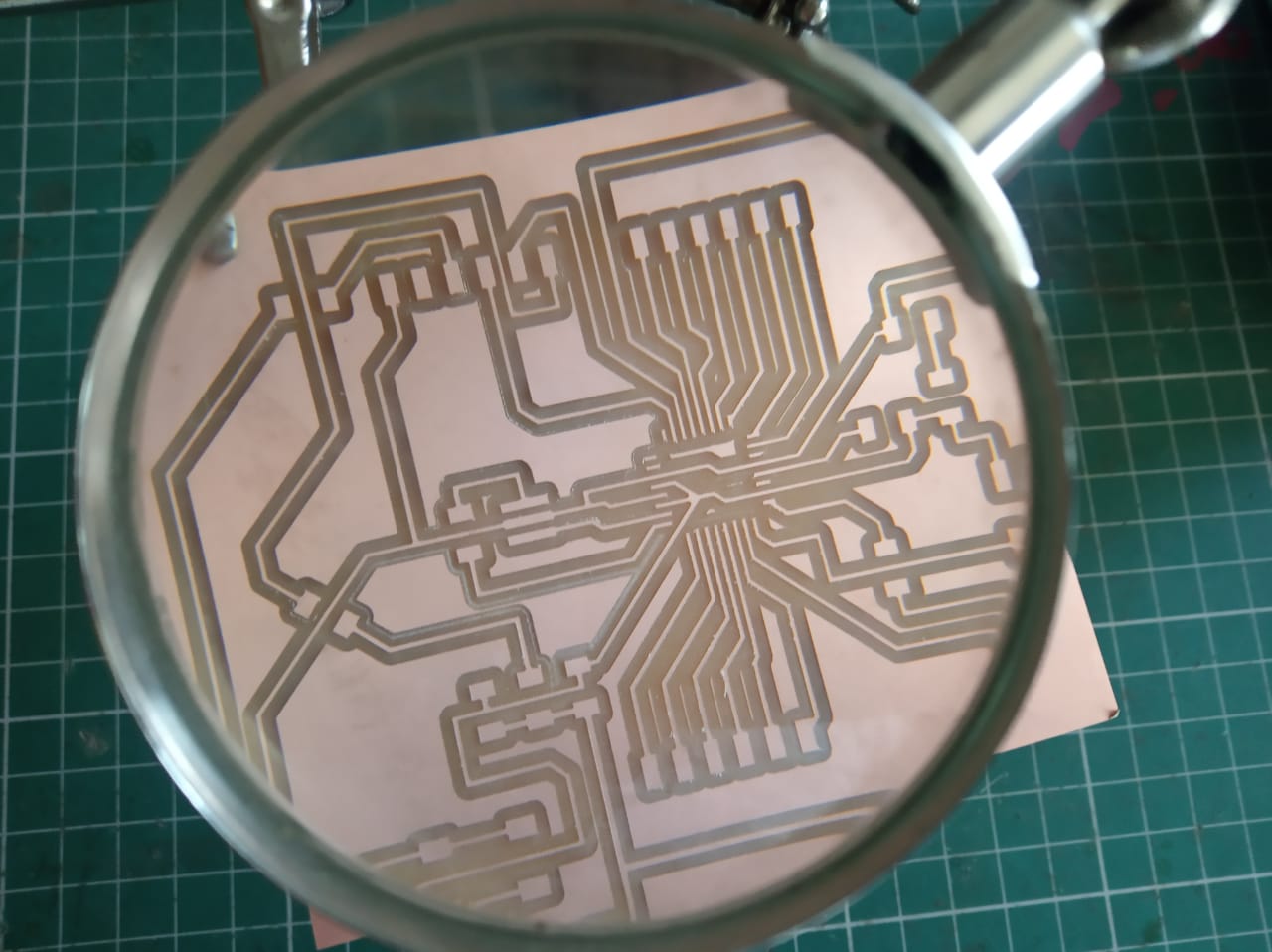
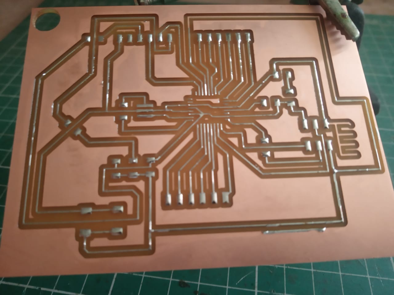
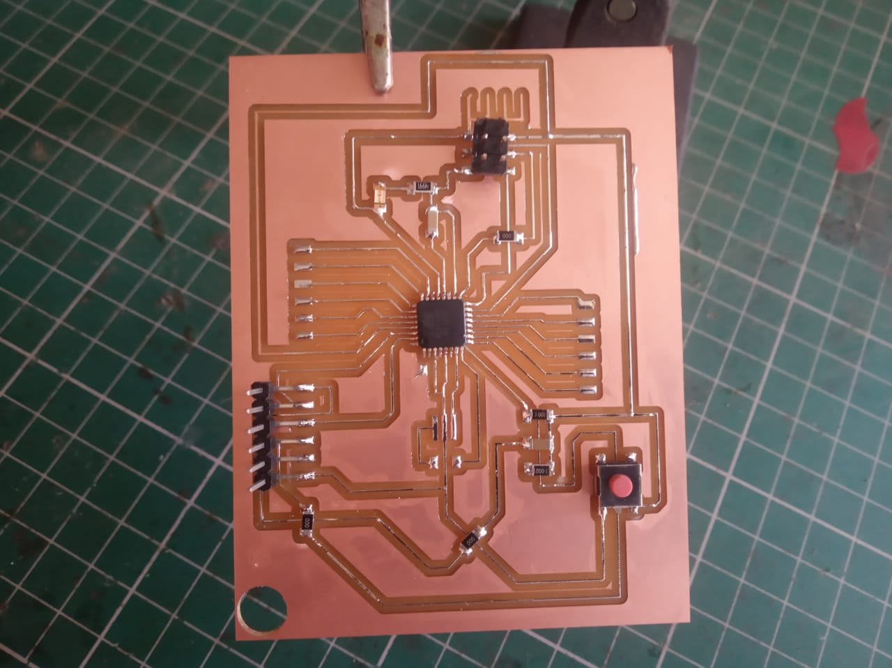
Milling & Soldering of Atmega 328p board
After i finished my schematic and board design work i took png of it and using fab mod i generate rml file of it.This rml is loaded in Vpanel a third party software for SRM -20.So lets begin milling the atmega 328p.
Interfacing Board with sensors
In this section i am going to show the interfacing of Atmega 328p board which acts as a brain here & to this brain i am going to give input through LM 35 sensor (Part of project).After getting the input from LM 35 sensor our atmega 328p will process that input.So for that i need to interface LM 35 to Atmega 328p board.So lets do it.
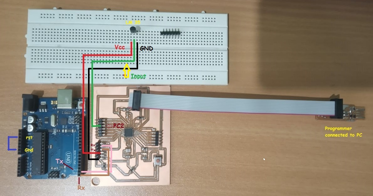
As you can see in above diagram i used Arduino uno board and i need to tell you the reason of using Arduino board.After i interfaced with sensor with microcontroller i want to see the data taken by sensor on serial monitor of arduino.So microcontroller transmit this input data on serial monitor of Arduino IDE serially.So Atmega 328p will transmit this data to PC and PC will receive it serially.For that i can used FTDI cable to estlablish a serial communication but unforatuantely it is not working at all.So i used Tx and Rx pins of Arduino for this serial communication between atmega 328p microcontroller and PC s(Serial monitor).
Used of arduino board is just adjustment.You can used FTDI cable to establish a serial communication.
Install the Atmega 328p Libraries in Arduino IDE
Open the Arduino IDE preferences window and add the following URL to the Additional Boards Manager URLs list:
Reference:https://github.com/carlosefr/atmega
Programming of my ATmega 328p
Tutorial 1: LM 35 (Body temp )sensor with Atmega 328p board
Ok i am ready with my board.Now i want to write a program to read the value from LM 35 sensor (input device) by atmega 328p and print it on serial monitor.Here i shown you the arduino code.Click here to check the interfacing diagram of LM 35 with atmega 328p board.Lets checked it out.
Program:
#include <SoftwareSerial.h>

//initializes/defines the output pin of the LM34 temperature sensor
int outputpin= PC2;
//this sets the ground pin to LOW and the input voltage pin to high
const int RX = PD0;
const int TX = PD1;

SoftwareSerial mySerial(TX, RX);

void setup()
{
//pinMode(outputpin,INPUT);
mySerial.begin(9600);
}

//main loop
void loop()
{
//Serial.begin(9600);
int rawvoltage= analogRead(outputpin);
float millivolts= (rawvoltage/1024.0) * 5000;
float fahrenheit= millivolts/10;
mySerial.print(fahrenheit);
mySerial.println(" degrees Fahrenheit, ");

float celsius= (fahrenheit - 32) * (5.0/9.0);

mySerial.print (celsius);
mySerial.println(" degrees Celsius");
delay(500);

}
Test Input device
Group assignment:Probe LM 35 analog levels
To check the analog levels of input devices we used LM 35 body temprature sensor which was used in my individual assignment.First i studied about the pin configuration of LM 35 and tried to explain to my fab mate.Then i also told them fetures of LM 35 as well.I used atmega 328p board of made by me inthis week and interfaced the LM 35 to it.
Features:
Code:
Go to Vikram page to check the code which read sensor data
Observation:In the following video i tried to show you change in voltage levels as temperature with respect to change in voltage levels.So in the first half of video you can see intially LM 35 is tested without having any heating material around it.I have observed the voltage levels on DSO.To measure the voltage level for respective temprature i connect DSO probe to LM 35 and check the corrosponding voltage levels and it was found to be 336V.Then in seconf half of video i kept hot soldering gun near LM 35 sensor to heat up.Then i measure the voltage levels i found on DSO is around 403mV.So change in voltage levels as sensor kept closed to any heating materail that indicate that it wont show the ambient temperature.
We select channel 1 of DSO and connect positive probe to data pin of LM 35 sensor and other probe connected to GND terminal.Then we observed the analog signal on DSO.