"Hi everyone ,Week 11 output devices begin.As i planned to work on my project related thing in output week followed by input week.I hope i will get the things properly.I am thinking about my final project where i have decided to used LCD display on sever side board .So in this week i am hopeing to interfaced my Server board along with LCD display with LM 35.My major goal of this week is to work on my output board having LCD display and LED's and test the code using ardiono IDE .So lets start working on output devices.
Learn differnt output devices
- Measure the power consumption of an output device
Group Assignment
- Add an output device to a microcontroller board you've designed, and program it to do something
Individual assignment
Hero shot
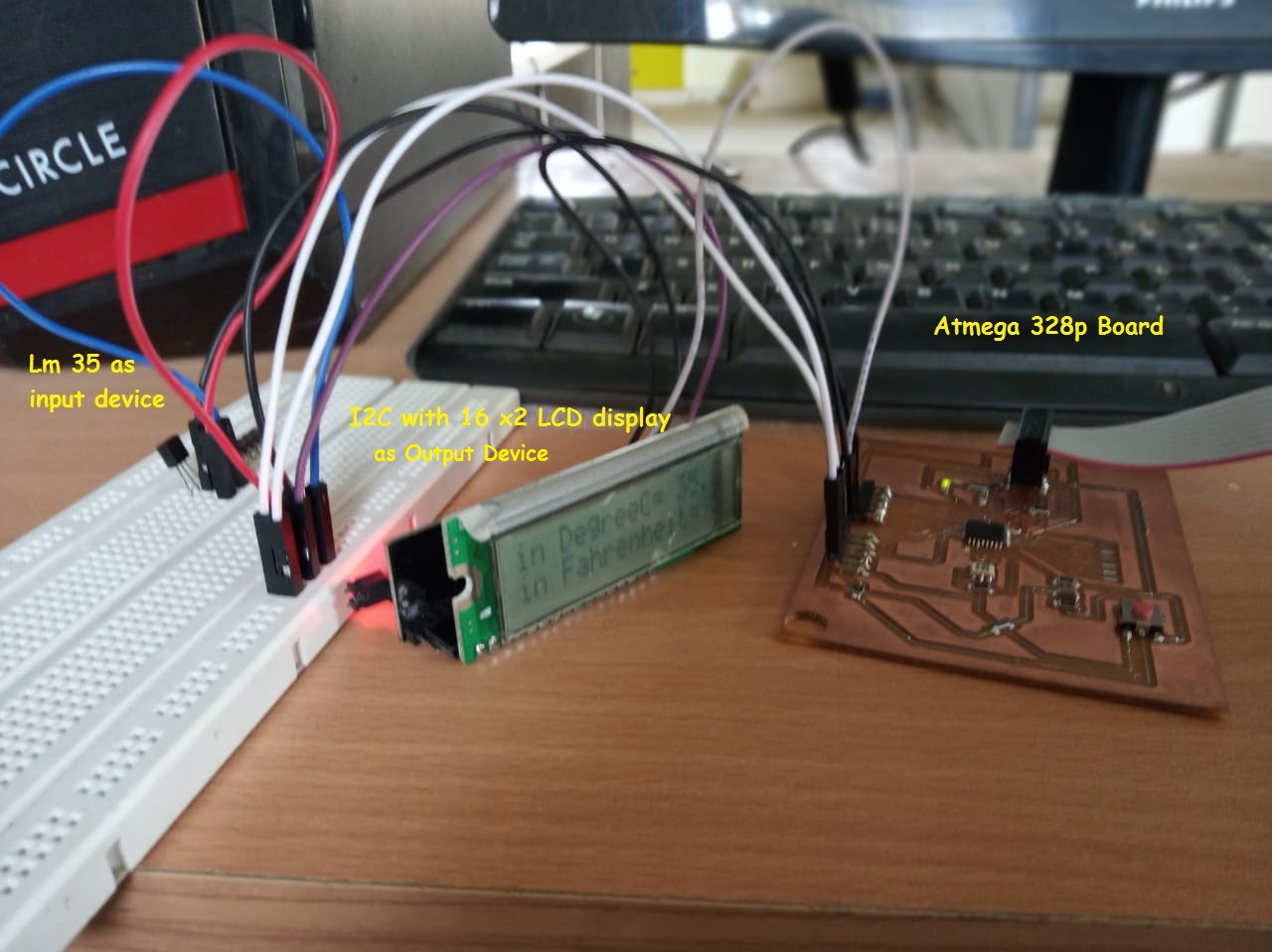
Table of Content
Objectives
About output device:
An output device is used to send data out of the system.Output device is any piece of computer hardware equipment which converts information into human-readable form. It can be text, graphics, tactile, audio, and video.Some of the output devices are Visual Display Units (VDU) i.e. a Monitor, Printer.So in short all we need an output device to display the information in the form of text ,graphics.
So as part of my output device which i am going to used in my final project is Text display.For that i referred Neil's document of output devices week.Where i found three display.LCD,OLED & TFT.
About LCD Display:
What is LCD 16 * 2?
An liquid-crystal display (LCD) is an electronic display module which uses liquid crystal to produce a visible image. The 16×2 LCD display is a very basic module commonly used in DIYs and circuits. The 16×2 translates o a display 16 characters per line in 2 such lines. In this LCD each character is displayed in a 5×7 pixel matrix.(electronicsforu)

Top View
(Note:Please go through the following things in detailed.Dont jump to another topic.I also skip this part which cause unnecessary problem.So to avod this read the following thing carefully.)
What is the cost of LCD display?
The LCD I am going to used is of $9.65.For more information visit website
Pin daigram

Top View
Back View
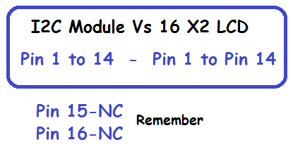
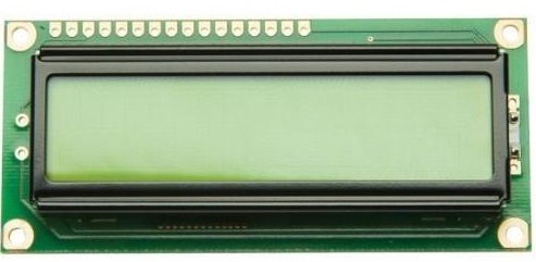
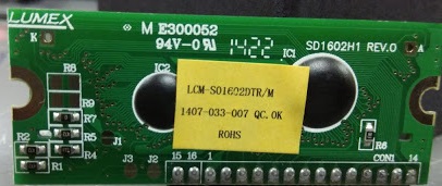
In our FAB inventory we have LCM-S01602DTR/M 16 X 2 LCD display .The 16 X 2 LCM-S01602DTR/M pin out is shown below.
( Remember: Pin15 & Pin16 are not connected pins.So you dont need to connect anything to it.So just interface the Pin 1-Pin 14 to backpack)
Features
Commands
The commands of LCD 16X2 include the following.About I2C protocol
What is I2C?
what is i2c. I2C (I-square-C i.e I2C) means inter-integrated communication protocol. This is usually used to communicate between one master and multiple slaves. One of the best things about using I2C is we can reduce the connections (wiring). If you use normal LCD display, you need a total number of connections are 12. If you use I2C LCD display, you need only just 4 connection. By seeing the above example you may know the advantage of I2C protocol. I2C protocol is also known as 2 line protocol.
Pin configurations
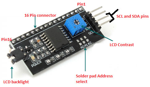
If you properly have seen the picture above, you will see a black adapter. That black adapter uses the PCF8574T IC chip which converts I2C serial data to parallel data for the LCD display. The blue color component you have seen in the above picture is a potentiometer which is used to adjust the brightness of the display.
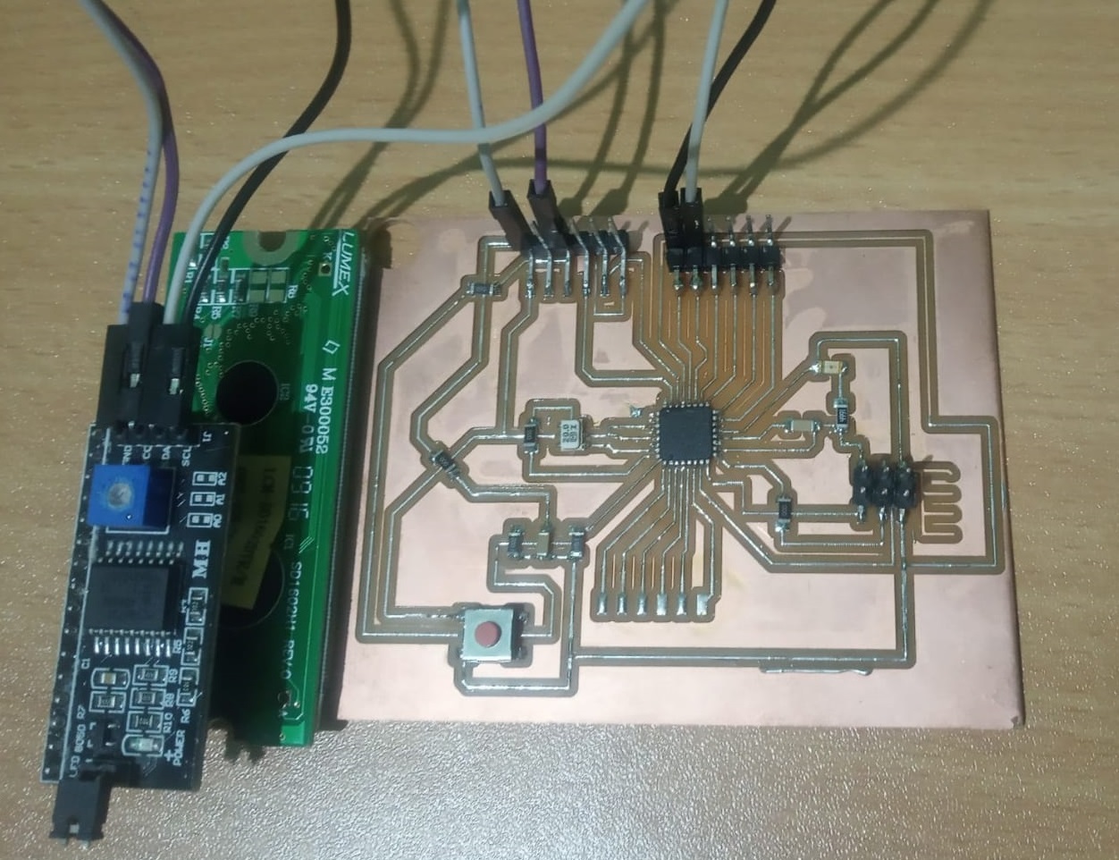
Interfaced I2C with 16X2 LCD(LCM-S01602DTR/M)

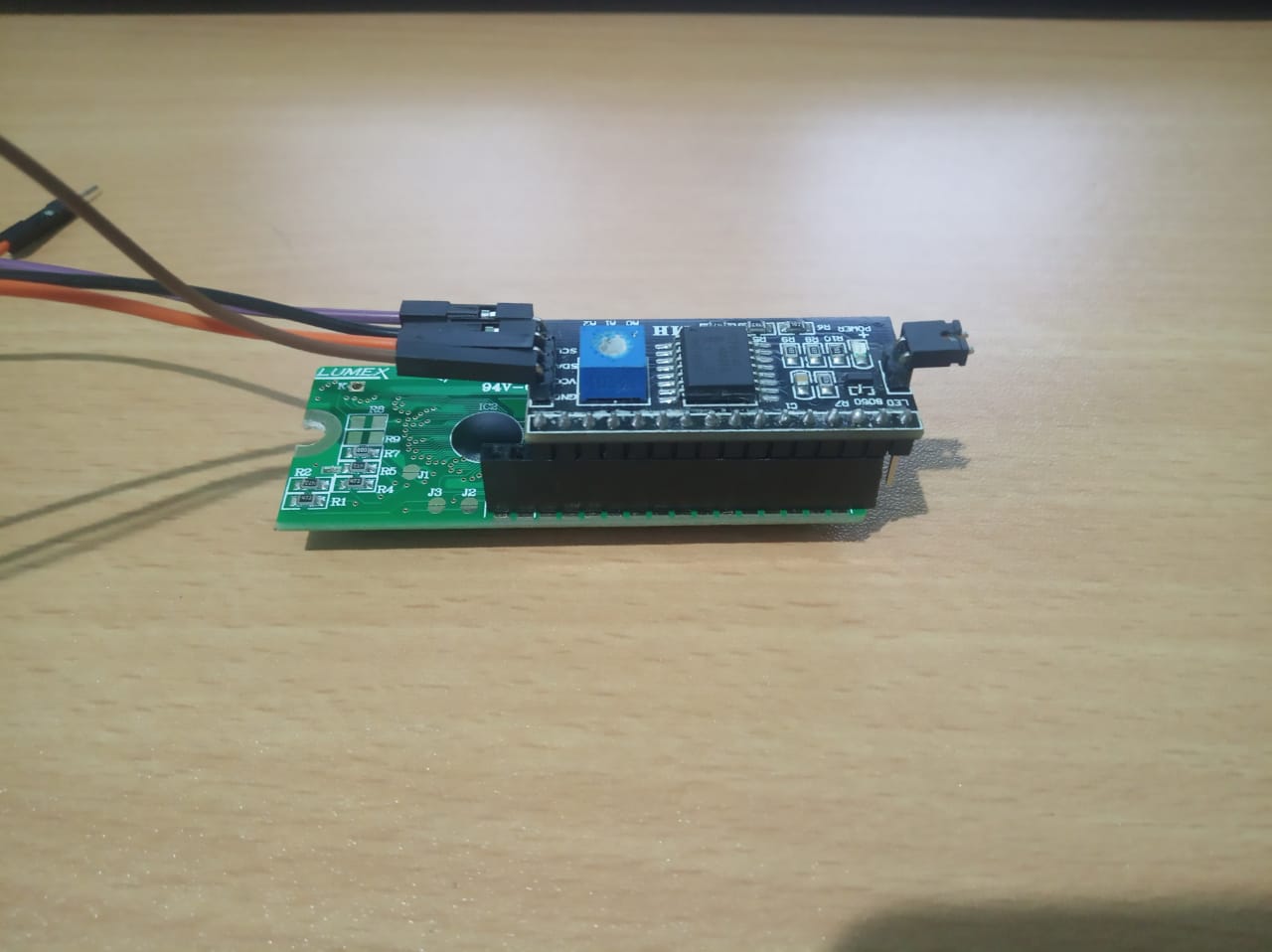
Remember:In above interfacing i used LCM-S01602DTR/M 16X2 LCD.
Schematic & Board design
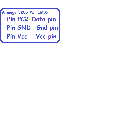
I have design Atmega 328p board.The detailed description of schematic and board design is explain in input week work.
Componant List
Install the LCD display Libraries in Arduino IDE
After interfacing microcontroller board with I2C 16 x 2 LCD module next step is to download Liquid crystal I2C library.Please follow the below steps:
Programming
To start programming part that you wish to upload you need to follow 3 steps procedure which i mentioned below.
Step1. Write a scanner program
Why?
As i used I2C module along with 16 X 2 LCD display first you need to find out address of I2C with 16 x 2 module.For that i used I2C scanner program to determine the address and also it is connected or not.So please refer the following code that scan the the I2C-bus for devices.If a device is found, it is reported to the Arduino serial monitor.Refer from https://playground.arduino.cc/Main/I2cScanner/
Program:
// This sketch tests the standard 7-bit addresses
// Devices with higher bit address might not be seen properly.
//

#include <Wire.h>


void setup()
{
  Wire.begin();

  Serial.begin(9600);
  while (!Serial);             // Leonardo: wait for serial monitor
  Serial.println("\nI2C Scanner");
}


void loop()
{
  byte error, address;
  int nDevices;

  Serial.println("Scanning...");

  nDevices = 0;
  for(address = 1; address < 127; address++ )
  {
    // The i2c_scanner uses the return value of
    // the Write.endTransmisstion to see if
    // a device did acknowledge to the address.
    Wire.beginTransmission(address);
    error = Wire.endTransmission();

    if (error == 0)
    {
      Serial.print("I2C device found at address 0x");
      if (address<16)
        Serial.print("0");
      Serial.print(address,HEX);
      Serial.println("  !");

      nDevices++;
    }
    else if (error==4)
    {
      Serial.print("Unknown error at address 0x");
      if (address<16)
        Serial.print("0");
      Serial.println(address,HEX);
    }
  }
  if (nDevices == 0)
    Serial.println("No I2C devices found\n");
  else
    Serial.println("done\n");

  delay(5000);           // wait 5 seconds for next scan
}
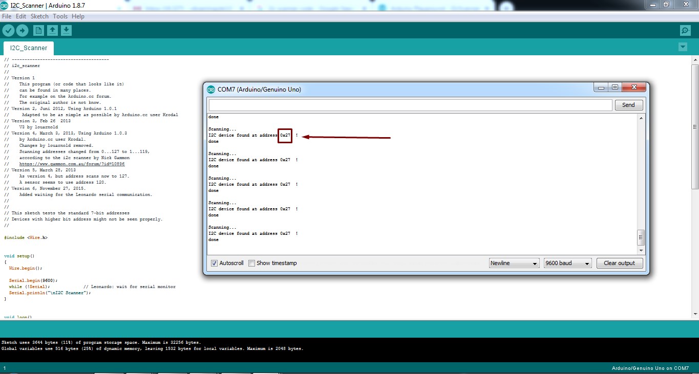
Step 2.Program to Display LM 35 sensor data to LCD display (This code will be diferent for you)
#include <Wire.h>
#include <LCD.h>
#include <LiquidCrystal_I2C.h>

LiquidCrystal_I2C  lcd(0x27,2,1,0,4,5,6,7); // 0x27 is the I2C bus address for an unmodified backpack
const int sensor=PC2; // Assigning analog pin A1 to variable 'sensor'
float tempc;  //variable to store temperature in degree Celsius
float tempf;  //variable to store temperature in Fahreinheit
float vout;  //temporary variable to hold sensor reading
void setup()
{
pinMode(sensor,INPUT); // Configuring pin A1 as input
Serial.begin(9600);
lcd.begin(16,2);
  lcd.setBacklightPin(3,POSITIVE);
  lcd.setBacklight(HIGH);
  delay(500);
}
void loop()
{
vout=analogRead(sensor);
vout=(vout*500)/1023;
tempc=vout; // Storing value in Degree Celsius
tempf=(vout*1.8)+32; // Converting to Fahrenheit
lcd.setCursor(0,0);
lcd.print("in DegreeC= ");
lcd.print(tempc);
lcd.setCursor(0,1);
lcd.print("in Fahrenheit=");
lcd.print(tempf);
delay(1000); //Delay of 1 second for ease of viewing in serial monitor
}
Learning outcomes
Group assignment
As a part of group assignment week we need to calculate the power of output device.So i decided to explain about how to measure voltage and currnet.So i explain my co fab mate about the concept of voltage and currnet.
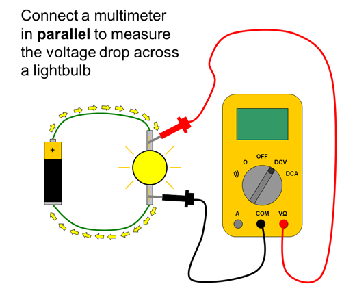
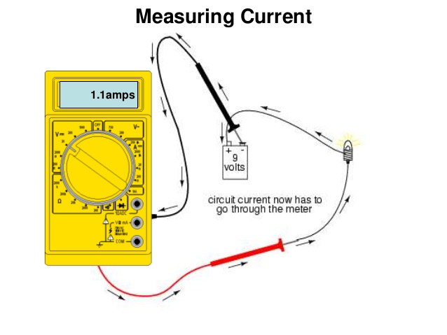
Safety tips for multimeter:
After understanding how to measure the voltage and current i decided to measure the voltage and current on my board and then try to calculate power of LCD display


To know how to calculate power please click on Group Assignment
