"Someting big, Yes rightly heard!In the week of Computer Controlled Cutting i am going to make bottle's and some other kichen stuff stand for our Lab kichen.Guess what to finished this we have very Bigggggg machine "ShopBot".I am very excited to get real hands on a big giant machine So lets start the week.
- Test runout
- Test alignment
- Test speeds
- Test feeds for your machine
Group Assignment
- Make a design
- Make a mill
- Make an assemble
- Make Something big
Individual assignment
Day 1
Enter into the Lab situated at Coep Pune away from 70 Kms from Vigyan Ashram(FabLAB).Day 1 to finished group assignment task
Visit Group assignments page
Day 2
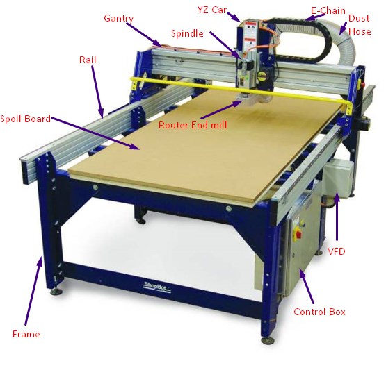
About BIG ShopBot Machine
After getting hands on the shopbot machine now the time is to worked on individual task.For that i planned my worked as follows.So guyes, Lets try to understand first about the machine followed by design part then procedure to generate the toolpath and finaly milling on machine.Lets go for it.Really excited.
What is CNC?
CNC or "computer numerical controlled" machines are sophisticated metalworking tools that can create complicated parts required by modern technology. ... The CNC term refers to a large group of these machines that utilize computer logic to control movements and perform the metalworking.
A ShopBot is an amazing do-all tool for precisely cutting, carving, drilling or machining all kinds of things from all kinds of materials. With a ShopBot, you use the included software to design your parts on your personal computer, then, like a robot, the computer controls the cutter to precisely cut your parts.
If you’re looking for a CNC solution for production that delivers high performance, high volume, speed and reliable power for all cutting tasks, ShopBot’s PRSalpha series of full-sized gantry tools will be your system of choice.
With enough production capability for a three-shift factory, ShopBot PRSalpha tools are our toughest, most sophisticated, gantry-based CNC routers. Using advanced technology for CNC cutting, drilling, carving and machining, the PRSalpha series tools deliver rapid transit speeds of 1800 inches per minute and cutting speeds of up to 600 inches per minute. Easy to configure and re-configure, learn and use, the PRSalpha CNC delivers affordable, full-production performance in digital fabrication of wood, plastic, aluminum, and other materials.
Refer from https://www.shopbottools.com/products/alpha.
During group task we interact with Ms.Apeksha who actually introduce the big shopbot machine to us and during the interaction she told us following specification of the machine.I listed out some of them.
| Sr.No. | Specifications |
| 01 | Fast, closed-loop Vexta alphaStep motors fitted with low-backlash, tapered-hob gear heads on all three axes (two on the X axis) -- alphaStep system monitors motor shaft positions to maintain synchronicity between signal and motion. |
| 02 | Tough precision linear bearings on the moving gantry and hardened steel rails for the x-axis. |
| 03 | Reliable rack-and-pinion power transmission on each axis. |
| 04 | Impressive cutting speeds of up to 600 inches per minute (depending on cutting bit and material) and rapid transit speeds of 1,800 inches per minute. |
| 05 | Step resolution of .0004”. |
| 06 | Positional accuracy of +/- .002”. |
| 07 | Sealed Industrial UL Certified Control Box. |
| 08 | Emergency Stop disconnect switch in the Control Box with integrated and cabled remote Emergency Stop Buttons. |
| 09 | Z-zero Touch-Off Plate and XY Proximity Switches. |
| 10 | ShopBot Control System software to run your CNC. |
Following are the specifiaction which we listed out while interacting with insterctors.

For more details you can visit the official site of shopbot here.
Now the time is come to talked about the How this CNC machine works?.When we asked the Ms.Apeksha to start the machine oh my God i cant belived there was a huge machine sound.We all get shocked but then we weared some personal protections.
How ShopBot Works?
ShopBot Tools, like all CNC tools, move a cutter around a big table (X and Y axes) and move it up and down as well (Z axis) allowing it to make 3D movements and cut all sorts of shapes. The cutter looks like a drill bit and is spun by a motor called a router or spindle. ... A ShopBot can also cut circles and holes.
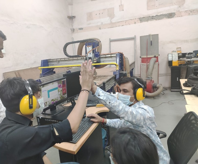
This image is taken during our group assignment work
Day3 & 4
Design steps in FreeCad
Since i am planning to design somethning big and usefull for our FABLAB i just took a time and and asked to my lab instructor what they required for the lab which may be usefull to them.So they told me that they need a one space where they can put differents componant boxes,color bottles etc.So accordingly i design the things what thay wanted.So lets take a tour of this week.
Side plate
Objectives:
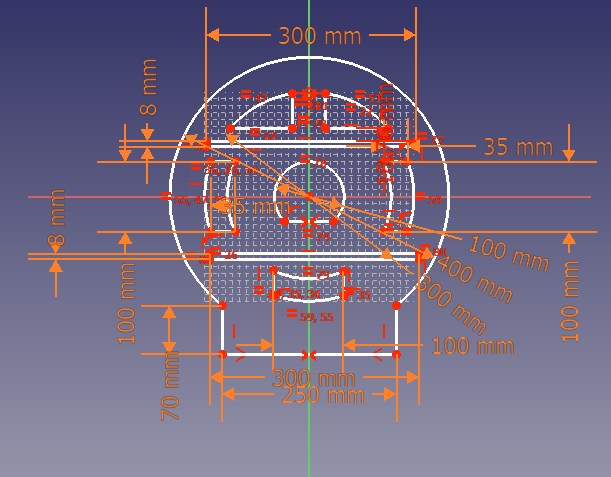
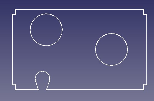
Step 1.As you can see i have design the side plate of circular one.Also i draw the design as well so that it looks good.And it should not be conventional.Also i make the design parametric one so that i can make necessary changes in the dimensions as well(Advantages of parametric design).
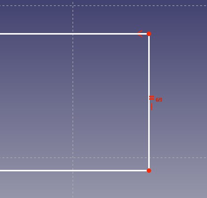
Step 2.In this image i have shown you two spot.These spot will be for to fixed the another plate(middle plate) into it
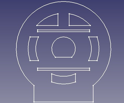
Step 3.Finally this is how my slide plate look and i am also happy that now i can used the design software to mahe the things which i wish .
Middle plate
Objective:
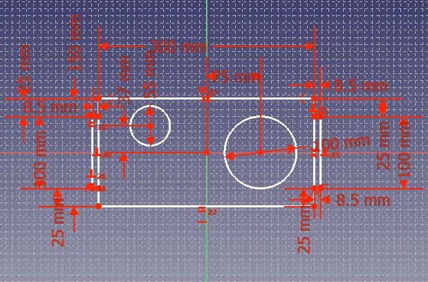
Step 1.As you can see first i design the thing using freeCad software and try to meet the objectives which i was stated earlier.Accordingly i design it and give parametric dimension to them.
Step 2.Look at the design where i have shown you two hole with different dimensions and corner spot as well.Also while giving dimension i make sure middle plate should get pressed fit into the slide plate properly.For that i need to refer the group assignments where we do all calculations of kerf and so on.
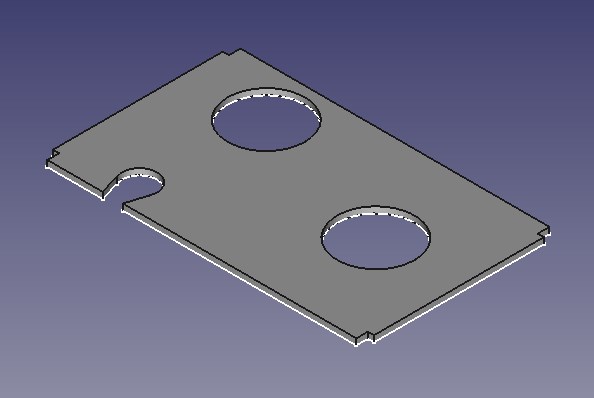
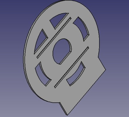
Step 3.Finally the design looks like this.
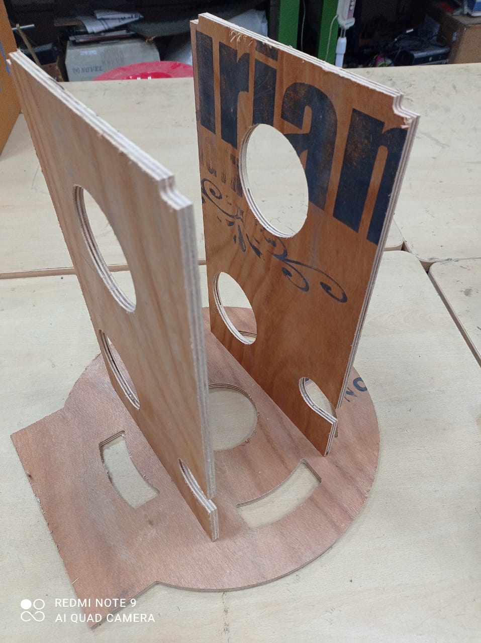
Joinning the whole assembly
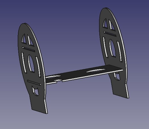
After designing slide plate and middle plate now the time is to press fit both of them.So this screenshot tell you joining of both plate into each other.
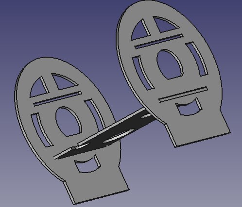
Another view:
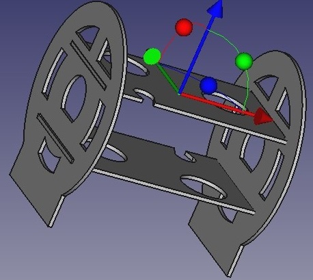
Finally i joined both plate upper and lower one into the slide plate .Now , i am satisfied and hoping shopbot will milled my design properly.
Day5 Braeking News :Covid 19 enter in INDIA
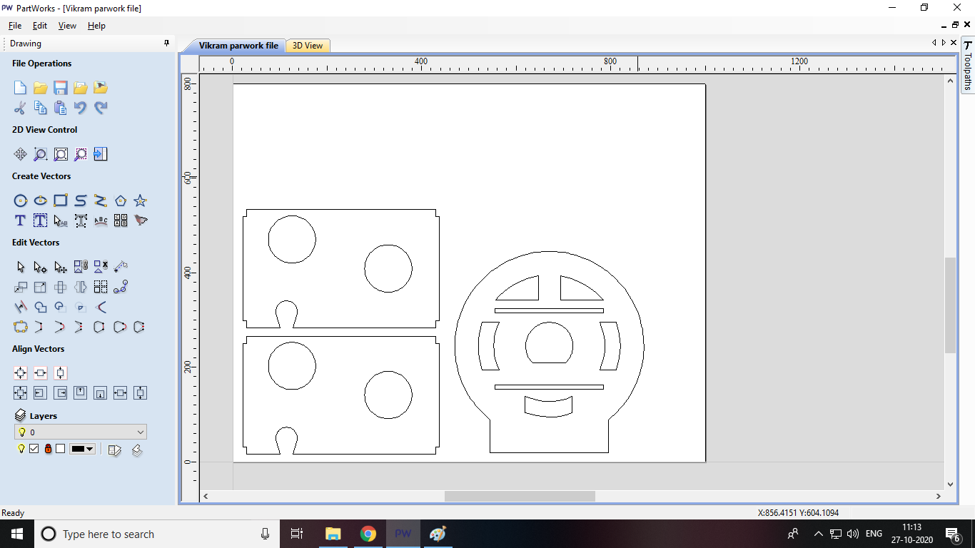
Procedure to generate the toolpath
Once i finished the my design i come to the lab once again.So first I decided to generate the toolpath.As my instructor told me procedure to generate the toolpath as per as our machine is corncenrd.
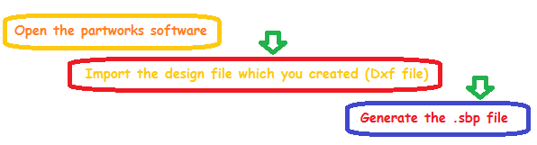
So lets go and see the step by step procedure
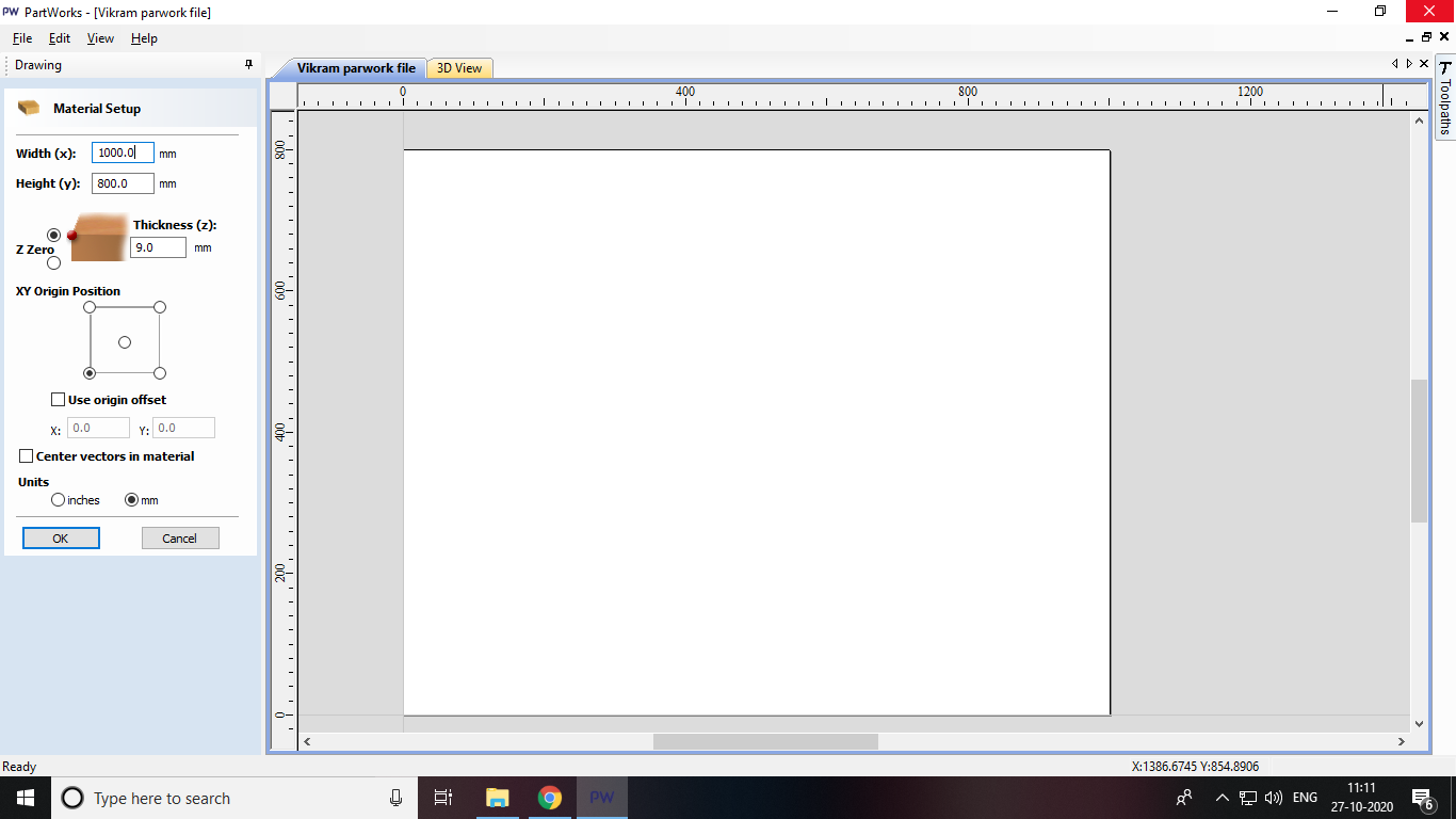
Step 1
In this step i am going to assign certain material parametars which needed for the machine to understand what size of material you are loading ,thickness material etc.So i listed out material settings below
*This will change as per your design size
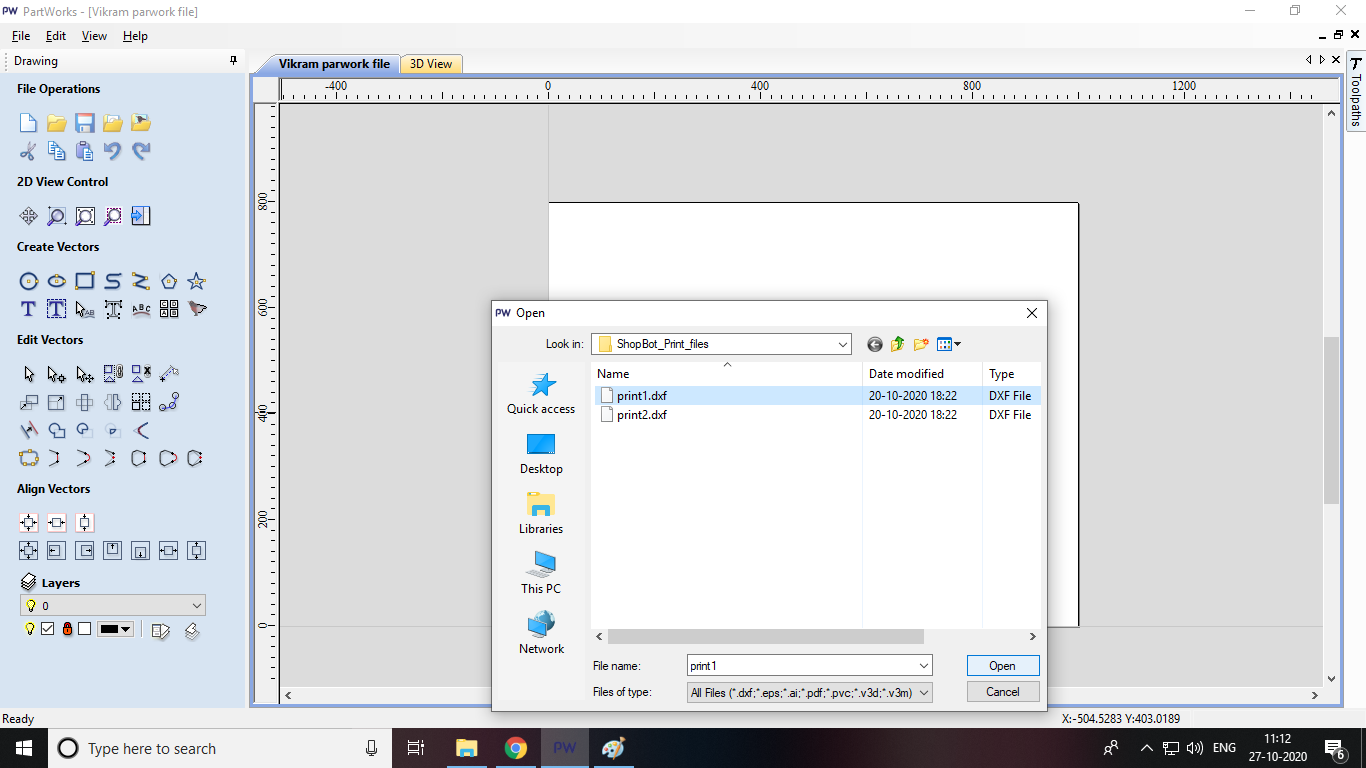
Step 2
Step 3
Step 4
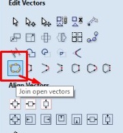
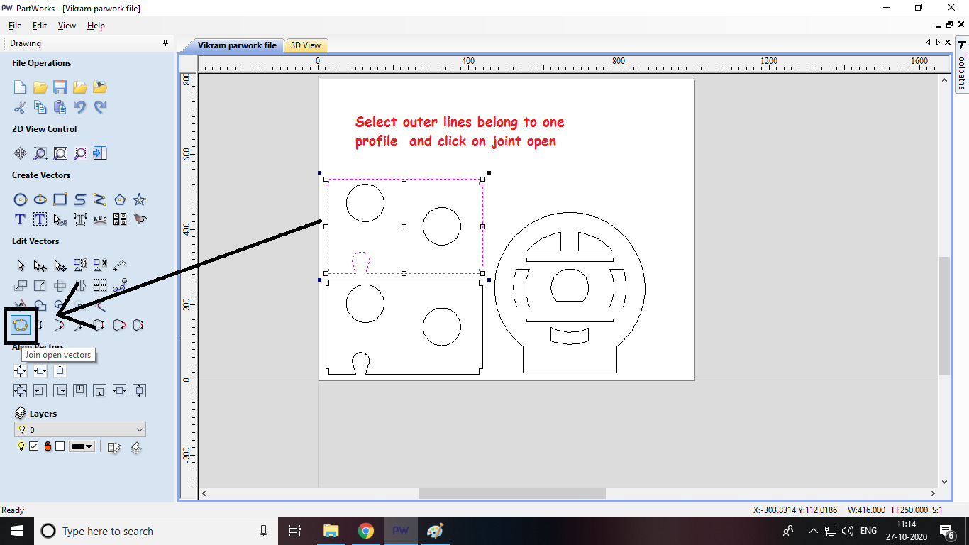
Now this an important step.When i design my sketch in freecad software all vertcale and horizantal lines are seperated from each other (even though it looks joined) with this we cant generetae the toolpath.So for that we need to select all lines and joined them first.First we need to select all lines(inner as weel as outer parts lines) and then click on menu named as Joined open vectors.Make sure that while selecting lines it should be belong to one profile only not others profile.In my case first i select all four vertcale and horizantal lins of outer profile and then joined open vectors.Similarly for inner profile such as circles.
Step 5
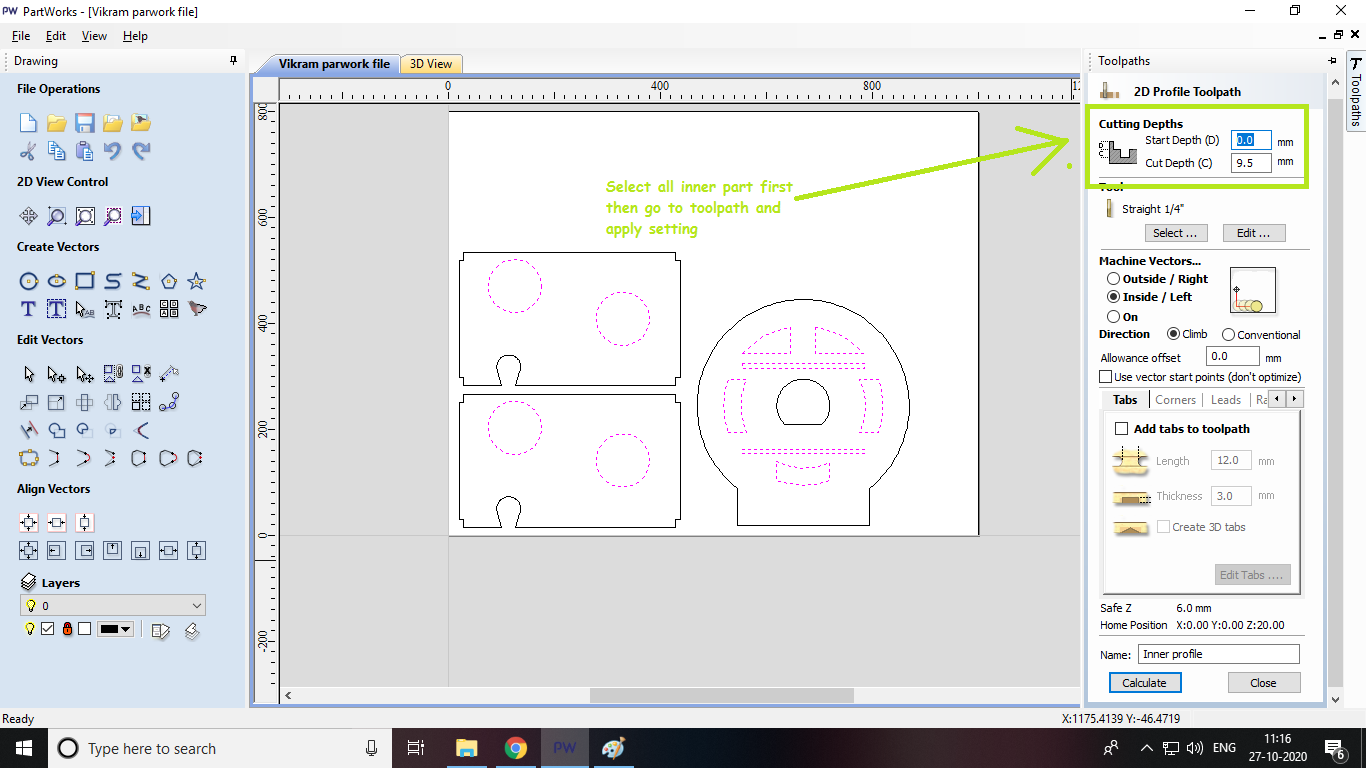
After joining both inner and outer profiles now next step is set the cutting depth, select the tools for inner as well as outer profile.
I set Start depth=0mm (the point at which tool of machine touches to surface of plywood)
cut depth=9.5mm (It should be maximum than selected thickness of material i.e plywood so that your tool cut the materail throughout.)
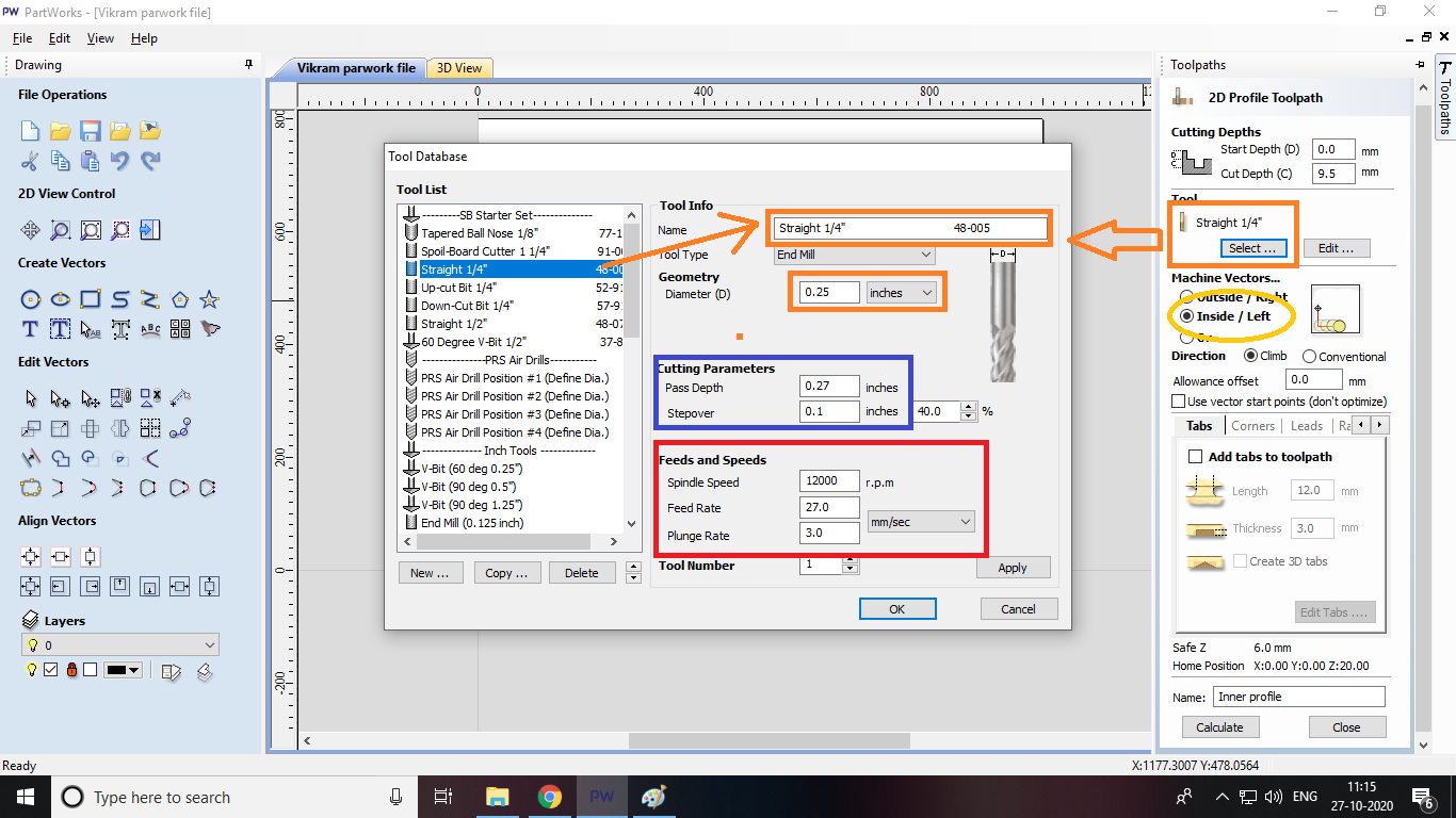
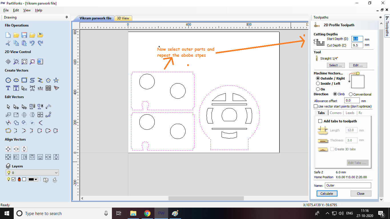
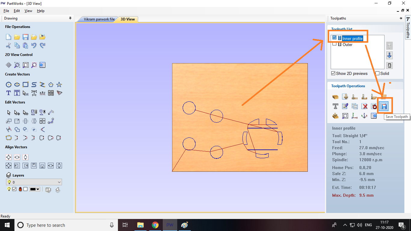
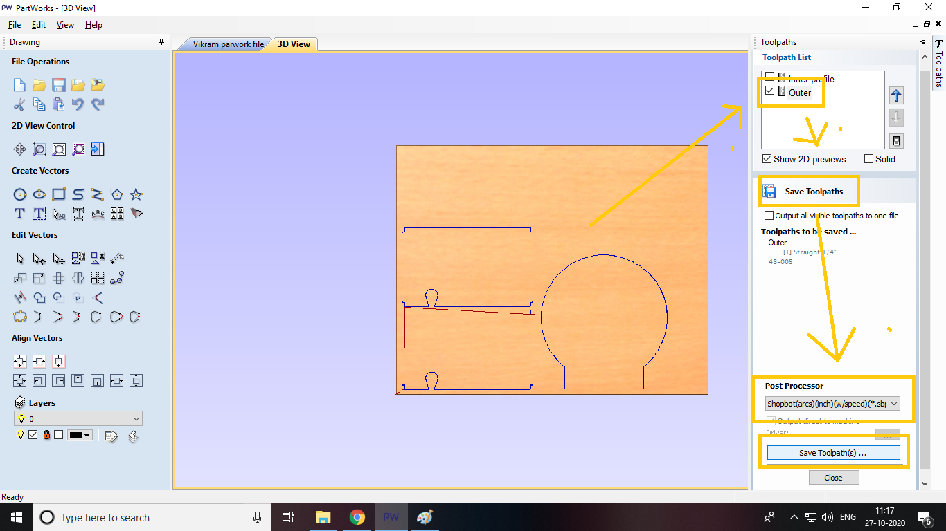
Step 6
Miling on ShopBot
Now the time is come to milled my design on machine and guess what shocking unfortuantely Due to COVID-19 Virus,Goverment of INDIA annouced completely Lockdown, all educational institutes till date.Due to this I cant finished my milling part on the machine which is available in COEP Lab.So i have to come back to our Fab Lab at Vigyan Ashram to finish next assignments.
Before the lockdown announced Fortuently we got hands on shopbot machine where we went through the all kinds of things as a part of group assignment like how to used the machine ,what softwares need to used,about specification,different parts of machine and generate the toolpath and run the machine.Please go through the group assignment page to view this.
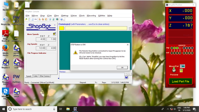
Step 7
Shopcontrol software is used to run the Shopbot CNC tools.Using the different commands you can move the tool and run a shop bot part file(.sbp file)
Step 8
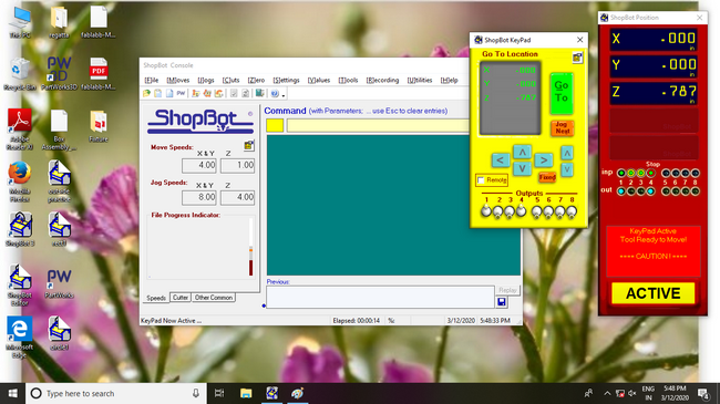
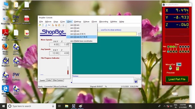
Set X,Y,Z origin first using the command.
Step 9
Step 10
Note:Make sure you put on safety glasses,hearing protection,turn on the spindle and vacuum.
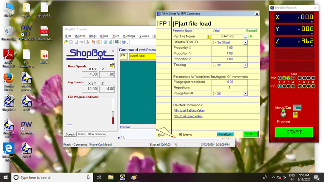
Step 11
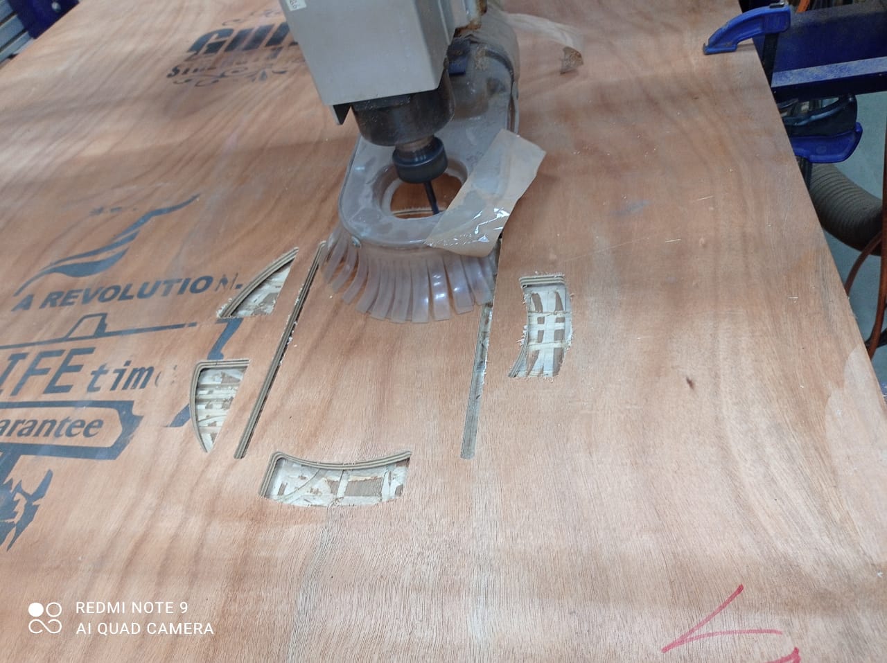
As you can see machine start milling my first object Happy........
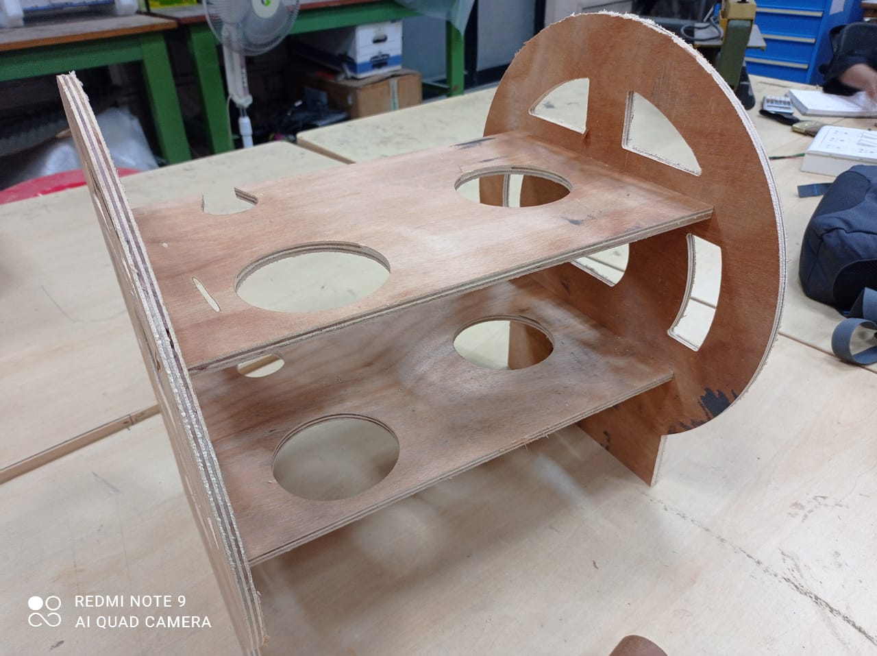
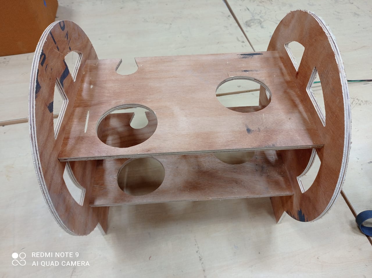
Cutting part
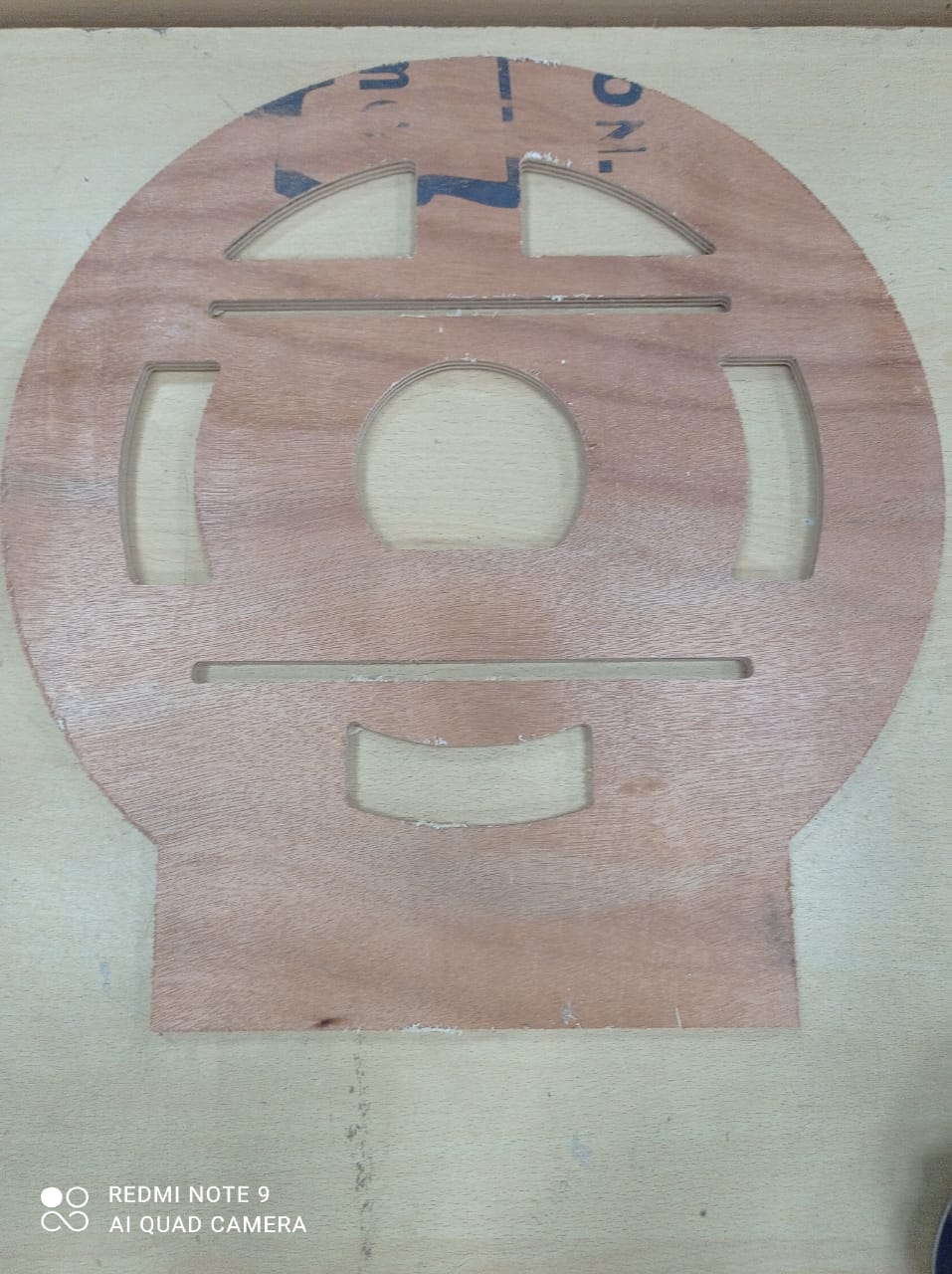
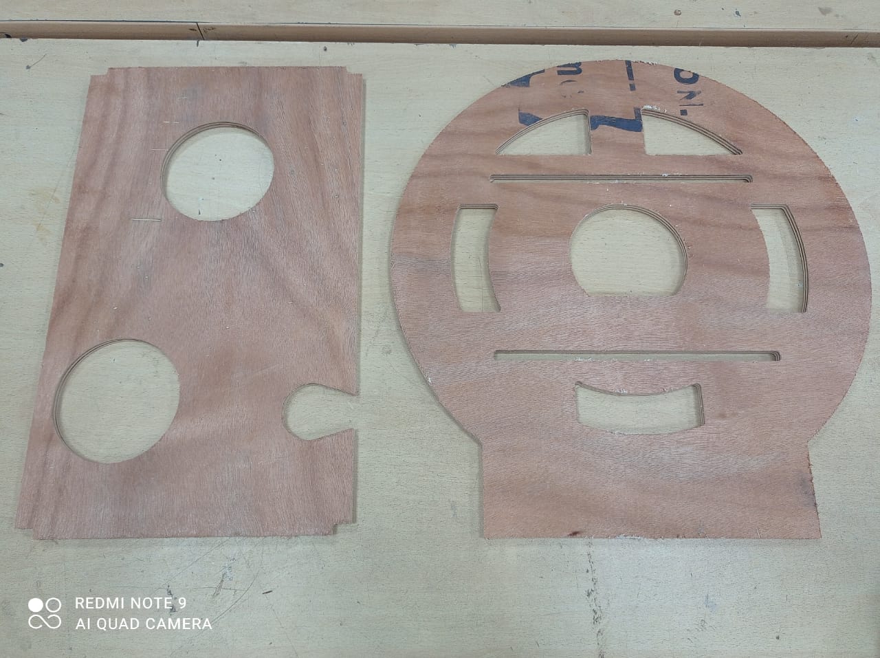
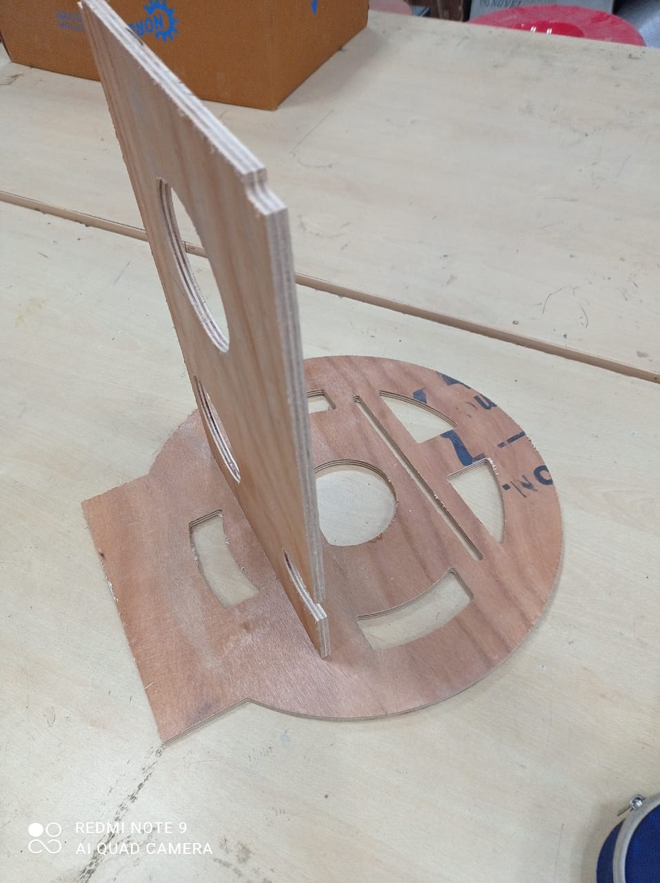
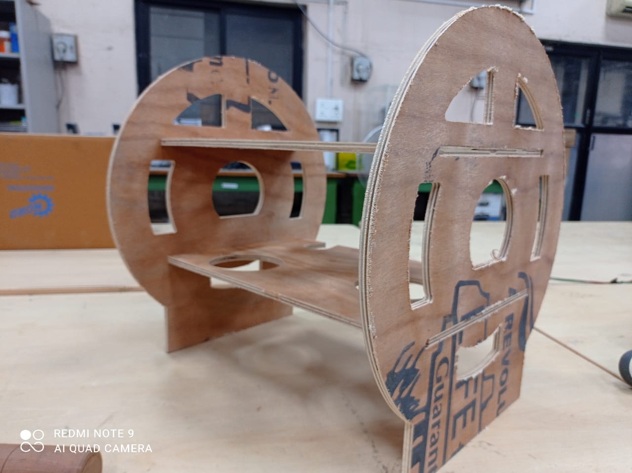
Assembling the part finally...
Whats problem with CNC machine?
I've been doing a lot of parametric modeling for CNC made furniture using fred Cad. It's been looking good and i have made above models to mills.The parts i have mill is shown above.
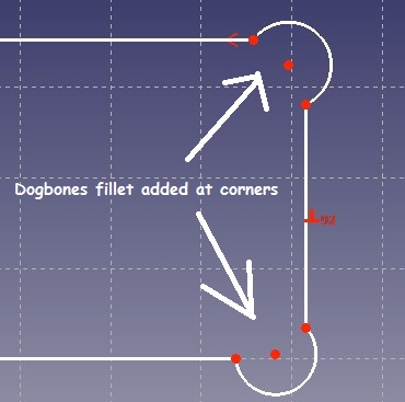
CNC machines use round bits and they don't make hard inside corners. To make square cornered parts fit into these rounded inside corners we use "dog bones". Essentially you dive the bit into the corner to make a cut
This can cause problems when mating parts as the part tooled might not fit in the formed hole or slot:
Whats is the solution
A DogBone Fillet is a solution to this problem. Although “DogBone” is a commonly used term in the field of CNC Cutting and milling.The DogBone Fillet command is different to a normal Fillet command because it creates a circular arc that is outside of the edges. The point of intersection for both edges is actually the mid-point of the arc.